11
CHAPTER
Wireless
413
WLAN
Basic Service Set (BSS) ad hoc
access point transceiver
Extended Service Set (ESS) hand-off roaming CSMA/CA DSSS ISM FHSS pseudorandom hopping sequence OFDM U-NII MIMO Wi-Fi SSID site survey inquiry procedure paging procedure piconet pairing Passkey WiMAX BWA NLOS last mile Radio Frequency Identification (RFID) backscatter Slotted Aloha beacon WPA EAP RADIUS
KEY TERMS
● Define the features of the 802.11 wireless
LAN standard
● Understand the components of the wireless
LAN
● Explore how wireless LANs are configured
● Examine how site surveys are done for
wire-less LANs
● Investigate the issues of securing a wireless
LAN
● Explore how to configure a
point-to-multi-point wireless LAN
OBJECTIVES
11-1 Introduction
11-2 The IEEE 802.11 Wireless LAN Standard
11-3 802.11 Wireless Networking 11-4 Bluetooth, WiMAX, and RFID
11-5 Securing Wireless LANs
11-6 Configuring a Point-to-Multipoint Wireless LAN: A Case Study Summary
Questions and Problems
CHAPTER OUTLINE
11-1
INTRODUCTION
This chapter examines the features and technologies used in the wireless local area network (WLAN). Wireless networking is an extension of computer networks into the RF (radio frequency) world. The WLAN provides increased flexibility and mo-bility for connecting to a network. A properly designed WLAN for a building pro-vides mobile access for a user from virtually any location in the building. The user doesn’t have to look for a connection to plug into; also, the expense of pulling cables and installing wall plates required for wired networks can be avoided. However, a net-work administrator must carefully plan the wireless LAN installation and have a good understanding of the issues of using WLAN technologies to ensure the installation of a reliable and secure network.
This chapter addresses the basic issues of incorporating WLAN technologies into a network. The fundamentals of the IEEE 802.11 wireless LAN standard are ex-amined in section 11-2. This includes an overview of wireless LAN concepts and ter-minology, frequency allocations, and spread spectrum communication. The applications of wireless LANs are presented in section 11-3. This includes a look at different types of wireless LAN configurations, such as point and point-to-multipoint. Other wireless networking technologies are examined in section 11-4. This section looks at Bluetooth, WiMAX, and RFID. Anytime a signal is transmitted over the air or even through a cable, there is some chance that the signal can be in-tercepted. Transmitting data over a wireless network introduces new security issues. Section 11-5 examines the basic issues of securing WLAN communications. The last section (11-6) presents an example of configuring a wireless LAN to provide access for users in a metropolitan area.
11-2
THE IEEE 802.11 WIRELESS LAN
STANDARD
A typical computer network uses twisted-pair and fiber optic cable to interconnect LANs. Another media competing for use in higher data-rate LANs is wireless, based on the IEEE 802.11 wireless standard. The advantages of wireless include
• User mobility in the workplace
• A cost-effective networking media for use in areas that are difficult or too costly to wire
The concept of user mobility in the workplace opens the door to many oppor-tunities to provide more flexibility. Workers can potentially access the network or their telephones (via IP telephony) from virtually any location within the workplace. Accessing information from the network is as easy as if the information were on a disk.
The benefits of wireless networks in the workplace are numerous. To provide wireless connectivity, the network administrator must be sure the network services are reliable and secure. Providing reliable network services means the administrator must have a good understanding of wireless LAN configurations and technologies. This and the following sections examine the fundamentals of wireless networking; the 802.11 standard and its family, 802.11a, 802.11b, and 802.11g and 802.11n; and how WLANs are configured.
WLAN
The IEEE 802.11 wireless LAN standard defines the physical (PHY) layer, the medium access control (MAC) layer, and the MAC management protocols and ser-vices.
The PHY (physical) layer defines
• The method of transmitting the data, which may be either RF or infrared (al-though infrared is rarely used)
The MAC (media access control) layer defines • The reliability of the data service
• Access control to the shared wireless medium • Protecting the privacy of the transmitted data
The wireless management protocols and services are • Authentication, association, data delivery, and privacy
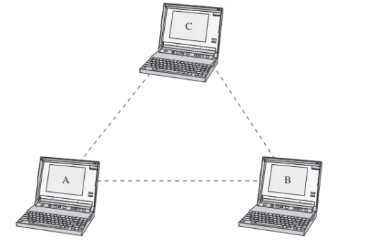
The fundamental topology of the WLAN is the Basic Service Set (BSS). This is also called the independent Basic Service Set, orad hocnetwork. An example of an ad hoc network is provided in Figure 11-1. In this network, the wireless clients (stations) communicate directly with each other. This means the clients have recog-nized the other stations in the WLAN and have established a wireless data link.
Section 11-2 • THE IEEE 802.11 WIRELESS LAN STANDARD 415
A B
C
FIGURE 11-1 An example of the independent Basic Service Set or “ad hoc” network.
The performance of the Basic Service Set can be improved by including an ac-cess point. The acac-cess point is a transmit/receive unit (transceiver) that intercon-nects data from the wireless LAN to the wired network. Additionally, the access point provides 802.11 MAC layer functions and supports bridge protocols. The access point typically uses an RJ-45 jack for connecting to the wired network. If an access point is being used, users establish a wireless communications link through it to communicate with other users in the WLAN or the wired network, as shown in Figure 11-2.
Basic Service Set (BSS)
Term used to describe an independent network
Ad Hoc
Another term used to describe an independent network
Access Point
A transceiver used to interconnect a wireless and a wired LAN
Transceiver
Access point
PC-E
Wired LAN
PC-A
PC-B
PC-C
PC-D
FIGURE 11-2 Adding an access point to the Basic Service Set.
If data is being sent from PC-A to PC-D, the data is first sent to the access point and then relayed to PC-D. Data sent from a wireless client to a client in the wired LAN also passes through the access point. The users (clients) in the wireless LAN can communicate with other members of the network as long as a link is established with the access point. For example, data traffic from PC-A to PC-E will first pass through the access point and then to PC-E in the wired LAN.
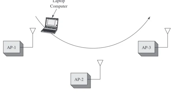
The problem with the Basic Service Set is that mobile users can travel outside the radio range of a station’s wireless link with one access point. One solution is to add multiple access points to the network. Multiple access points extend the range of mobility of a wireless client in the LAN. This arrangement is called an Extended Service Set (ESS). An example is provided in Figure 11-3. The mobile computer will establish an authorized connection with the access point that has the strongest signal level (for example, AP-1). As the user moves, the signal strength of the signal from AP-1 will decrease. At some point, the signal strength from AP-2 will exceed AP-1, and the wireless bridge will establish a new connection with AP-2. This is called a hand-off. This is an automatic process for the wireless client adapter in 802.11, and the term used to describe this is roaming.
Network access in 802.11 uses a technique called carrier sense multiple ac-cess/collision avoidance (CSMA/CA). In CSMA/CA, the client station listens for other users of the wireless network. If the channel is quiet (no data transmission), the client station may transmit. If the channel is busy, the station(s) must wait until trans-mission stops. Each client station uses a unique random back-off time. This technique prevents client stations from trying to gain access to the wireless channel as soon as it becomes quiet. There are currently four physical layer technologies being used in 802.11 wireless networking. These are direct sequence spread spectrum (DSSS), fre-quency hopping spread spectrum (FHSS), infrared, and orthogonal frefre-quency divi-sion multiplexing (OFDM). DSSS is used in 802.11b/g/n wireless networks, and
Extended Service Set (ESS)
The use of multiple access points to extend user mobility
Hand-off
When the user’s computer establishes an association with another access point
Roaming
The term used to describe a users’ ability to maintain network connectivity as they move through the workplace
CSMA/CA
Carrier sense multiple access/collision avoidance
FIGURE 11-3 An example of an Extended Service Set used for increased user mobility.
802.11 DSSS implements 14 channels (each consuming 22 MHz) over ap-proximately 90 MHz of RF spectrum in the 2.4 GHz ISM(industrial, scientific, and medical) band. The frequency channels used in North America are listed in Table 11-1. An example of the frequency spectrum for three-channel DSSS is shown in Fig-ure 11-4.
TABLE 11-1 North American DSSS Channels Channel Number Frequency (GHz)
1 2.412
2 2.417
3 2.422
4 2.427
5 2.432
6 2.437
7 2.442
8 2.447
9 2.452
10 2.457
11 2.462
In frequency hopping spread spectrum (FHSS), the transmit signal frequency changes based on a pseudorandom sequence. Pseudorandommeans the sequence appears to be random but in fact does repeat, typically after some lengthy period of time. FHSS uses 79 channels (each 1 MHz wide) in the ISM 2.4 GHz band. FHSS re-quires that the transmitting and receiving units know thehopping sequence(the or-der of frequency changes) so that a communication link can be established and synchronized. FHSS data rates are typically 1 and 2 Mbps. FHSS is not commonly used anymore for wireless LANs. It’s still part of the standard, but very few (if any) FHSS wireless LAN products are sold.
Section 11-2 • THE IEEE 802.11 WIRELESS LAN STANDARD 417
AP-1
AP-2
AP-3 Laptop
Computer
DSSS
Direct sequence spread spectrum
ISM
Industrial, scientific, and medical
OFDM is used in 802.11a, 802.11g, and 802.11n. Note that 802.11g/n use both DSSS and OFDM modulation.
FHSS
Frequency hopping spread spectrum
Pseudorandom
The number sequence appears random but actually repeats
Hopping Sequence
The order of frequency changes
FIGURE 11-4 An example of the three channels in the DSSS spectrum.
The maximum transmit power of 802.11b wireless devices is 1000 mW; how-ever, the nominal transmit power level is 100 mW. The 2.4 GHz frequency range used by 802.11b/g is shared by many technologies, including Bluetooth, cordless tele-phones, and microwave ovens.
LANs emit significant RF noise in the 2.4 GHz range that can affect wireless data. A significant improvement in wireless performance is available with the IEEE 802.11a standards. The 802.11a equipment operates in the 5 GHz range and provides significant improvement over 802.11b with respect to RF interference.
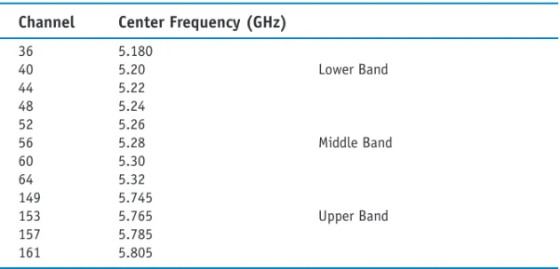
The 802.11a standard uses a technique called orthogonal frequency division multiplexing (OFDM) to transport the data over 12 possible channels in the U-NII (Unlicensed National Information Infrastructure). U-NII was set aside by the FCC to support short-range, high-speed wireless data communications. Table 11-2 lists the operating frequencies for 802.11a. Table 11-3 lists the transmit power levels for 802.11a.
TABLE 11-2 IEEE 802.11a Channels and Operating Frequencies Channel Center Frequency (GHz)
36 5.180
40 5.20 Lower Band
44 5.22
48 5.24
52 5.26
56 5.28 Middle Band
60 5.30
64 5.32
149 5.745
153 5.765 Upper Band
157 5.785
161 5.805
TABLE 11-3 Maximum Transmit Power Levels for 802.11a with a 6dBi Antenna Gain
Band Power Level
Lower 40 mW
Middle 200 mW
Upper 800 mW
2.412 CH 1
2.437 CH 6
2.462 CH 11
GHZ
OFDM
Orthogonal frequency division multiplexing
U-NII
Unlicensed National Information Infrastructure
IEEE 802.11a equipment is not compatible with 802.11b, 802.11g, or 802.11n. The good aspect of this is that 802.11a equipment will not interfere with 802.11b, g, or n; therefore, 802.11a and 802.11b/g/n links can run next to each other without causing any interference. Figure 11-5 illustrates an example of the two links operat-ing together.
Section 11-2 • THE IEEE 802.11 WIRELESS LAN STANDARD 419
802.11b/g
802.11a
FIGURE 11-5 An example of an 802.11a installation and an 802.11b link running alongside each other.
The downside of 802.11a is the increased cost of the equipment and increased power consumption because of the OFDM technology. This is of particular concern with mobile users because of the effect it can have on battery life. However, the max-imum usable distance (RF range) for 802.11a is about the same or even greater than that of 802.11b/g/n.
Another IEEE 802.11 wireless standard is IEEE 802.11g. The 802.11g stan-dard supports the higher data transmission rates of 54 Mbps but operates in the same 2.4 GHz range as 802.11b. The 802.11g equipment is also backward compatible with 802.11b equipment. This means that 802.11b wireless clients will be able to com-municate with the 802.11g access points, and the 802.11g wireless client equipment will communicate with the 802.11b access points.
The obvious advantage of this is that companies with an existing 802.11b wire-less network will be able to migrate to the higher data rates provided by 802.11g with-out having to sacrifice network compatibility. In fact, new wireless equipment support both the 2.4 GHz and 5 GHz standards, giving it the flexibility of high speed, compatibility, and noninterference.
Another entry into wireless networks is the 802.11n. This wireless technology can operate in the same ISM frequency as 802.11b/g (2.4GHz) and can also operate in the 5 GHz band. A significant improvement with 802.11n is MIMO(Multiple In-put Multiple OutIn-put). MIMO uses a technique called space-division multiplexing, where the data stream is split into multiple parts calledspatial streams. The different spatial streams are transmitted using separate antennas. With MIMO, doubling the spatial streams doubles the effective data rate. The downside of this is there can be increased power consumption. The 802.11n specification includes a MIMO power-save mode. With this, 802.11n only uses multiple data paths when faster data trans-mission is required—thus saving power.
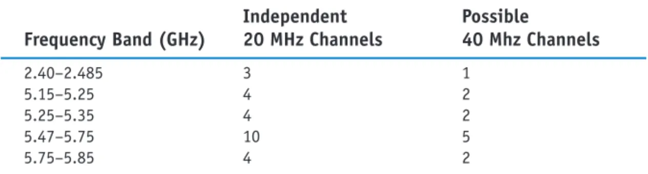
Table 11-4 lists the 802.11n frequency bands. This table shows frequencies in both the 2.4 GHz and 5 GHz range. The frequencies being used in the 5 GHz band are the same as those used in 802.11a, and note that there is the possibility of using both 20MHz and 40MHz channels.
MIMO
A space-division multiplexing technique where the data stream is split into multiple parts called spatial streams
TABLE 11-4 The 802.11n Frequency Bands
Independent Possible Frequency Band (GHz) 20 MHz Channels 40 Mhz Channels
2.40–2.485 3 1
5.15–5.25 4 2
5.25–5.35 4 2
5.47–5.75 10 5
5.75–5.85 4 2
Wireless networks also go by the name Wi-Fi, which is the abbreviated name for the Wi-Fi Alliance (Wi-Fi stands for wireless fidelity). The Wi-Fi Alliance is an organization whose function is to test and certify wireless equipment for compliance with the 802.11x standards, the group of wireless standards developed under the IEEE 802.11 standard. The following list provides a summary of the most common wireless standards:
• 802.11a (Wireless-A):This standard can provide data transfer rates up to 54 Mbps and an operating range up to 75 feet. It operates at 5 GHz (Modulation— OFDM)
• 802.11b (Wireless-B):This standard can provide data transfer rates up to 11 Mbps with ranges of 100 to 150 feet. It operates at 2.4 GHz. (Modulation— DSSS)
• 802.11g (Wireless-G):This standard can provide data transfer rates up to 54 Mbps up to 150 feet. It operates at 2.4 GHz. (Modulation—DSSS or OFDM) • 802.11n (Wireless-N):This is the next generation of high-speed wireless
con-nectivity promising data transfer rates over 200+ Mbps. It operates at 2.4 GHz and 5 GHz. (Modulation—DSSS or OFDM)
• 802.11i:This standard for wireless LANs (WLANs) provides improved data encryption for networks that use the 802.11a, 802.11b, and 802.11g standards. • 802.11r:This standard is designed to speed handoffs between access points or cells in a wireless LAN. This standard is a critical addition to 802.11 WLANs if voice traffic is to become widely deployed.
11-3
802.11 WIRELESS NETWORKING
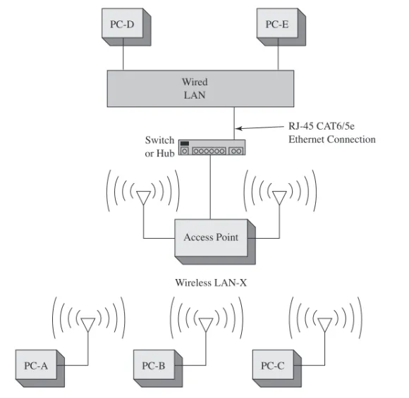
A wireless LAN can be configured in many ways to meet the needs of an organiza-tion. Figure 11-6 provides an example of a basic 802.11b/g/n WLAN configuraorganiza-tion. Each PC is outfitted with a wireless LAN adapter card. The PC cards come in many styles, such as PCI, ISA, or PCMCIA, and some units are external to the computer. The wireless adapter (wireless LAN adapter) is the device that connects the client to the wireless medium. The medium is typically a radio wave channel in the 2.4 GHz ISM band. The wireless medium can also be infrared, although this is not used very often. The following services are provided by the wireless LAN adapter:
• Delivery of the data • Authentication • Privacy
Wi-Fi
Wi-Fi Alliance—an organization that tests and certifies wireless equipment for compliance with the 802.11x standards
Section 11-3 • 802.11 WIRELESS NETWORKING 421
Access Point Wired
LAN
Switch or Hub
PC-E
Wireless LAN-X
PC-A PC-B PC-C
PC-D
RJ-45 CAT6/5e Ethernet Connection
FIGURE 11-6 The setup for a basic wireless LAN.
The connection to a wired LAN is provided by a wireless access point, which provides a bridge between the wireless LAN and the wired network. A physical ca-ble connection (typically CAT6/5e) ties the access point to the wired network’s switch or hub (typically Ethernet).
For example, computer A shown in Figure 11-6 sends a data packet to PC-D, a destination in the wired LAN. PC-A first sends a data packet over the wireless link. The access point recognizes the sender of the data packet as a host in the wire-less LAN-X and allows the wirewire-less data to enter the access point. At this time, the data is sent out the physical Ethernet connection to the wired LAN. The data packet is then delivered to PC-D in the wired LAN.
A question should come up at this point: “How does the access point know that the wireless data packet is being sent from a client in the wireless LAN?”
The answer is the 802.11 wireless LAN devices use an SSIDto identify what wireless data traffic is allowed to connect to the network. The SSID is the wireless
service set identifier, basically a password that enables the client to join the wireless network.
The access point uses the SSID to determine whether the client is to become a member of the wireless network. The termassociation is used to describe that a wire-less connection has been obtained.
SSID
Another common question is, “Why does the access point have two antennas?” The answer is the two antennas implement what is called “spatial diversity.” This an-tenna arrangement improves received signal gain and performance.
Figure 11-7 provides an example of the information displayed on the wireless adapter’s console port when an association is made. The text indicates that a connec-tion has been made to a parent (access point) whose MAC address is 00-40-96-25-9d-14. The text indicates this MAC address has been “added” to the list of associations. This type of information is typically available via the wireless manage-ment software that typically comes with the wireless PC or PCMCIA adapter.
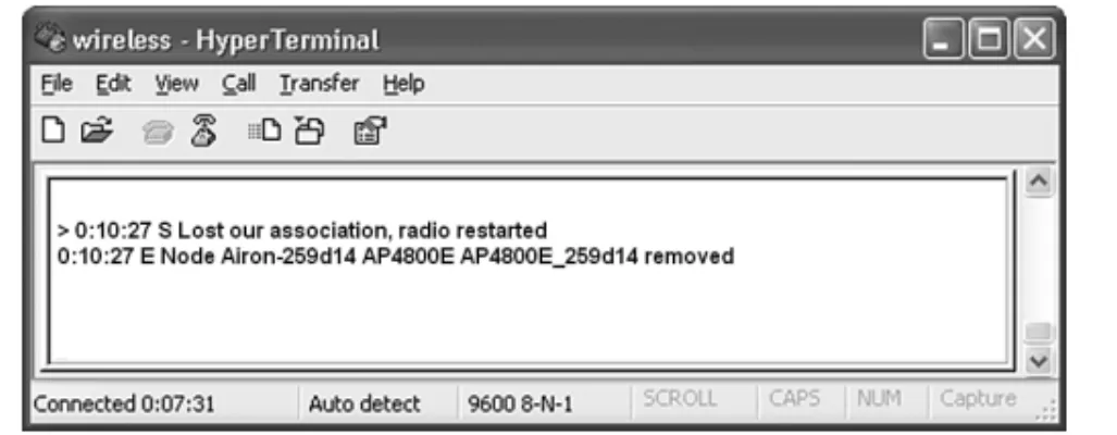
FIGURE 11-7 An example of the information displayed when an association is made by a client with an access point.
Access points use the association to build a table of users (clients) on the wire-less network. Figure 11-8 provides an example of an association table. The associa-tion table lists the MAC addresses for each networking device connected to the wireless network. The access point then uses this table to forward data packets be-tween the access point and the wireless network. The wireless client adapter will also notify the user if the client has lost an association with the access point. An example of this also is provided in Figure 11-8.
A wireless bridge is a popular choice for connecting LANs (running similar network protocols) together even if the LANs are miles apart. Examples are provided in Figure 11-9 (a) and (b). Figure 11-9 (a) shows a point-to-point wireless bridge. Each building shown in Figure 11-9 (a) has a connection from the wireless bridge to the building’s LAN, as shown in Figure 11-10. The wireless bridge then connects to an antenna placed on the roof, and there must be a clear (line-of-sight) transmission path between the two buildings, or there will be signal attenuation (loss) or possible signal disruption. Antenna selection is also critical when configuring the connection. This issue is addressed in section 11-5. The antenna must be selected so that the sig-nal strength at the receiving site is sufficient to meet the required received sigsig-nal level.
Figure 11-9 (b) shows how a wireless bridge can be used to connect multiple remote sites to the main transmitting facility. Each building uses a bridge setup sim-ilar to that shown in Figure 11-10. The bridge connects to its respective LAN. In this case, Bld-A uses an antenna that has a wide coverage area (radiation pattern). The key objective with antenna selection is that the antenna must provide coverage for all re-ceiving sites (in this case, Bld-B and Bld-C).
Section 11-3 • 802.11 WIRELESS NETWORKING 423
(a)
(b)
Bld #1 Bld #2
Bld-B
Bld-A
Bld-C
FIGURE 11-9 Examples of (a) point-to-point and (b) point-to-multipoint wireless bridge configurations.
Wireless LANs have a maximum distance the signal can be transmitted. This is a critical issue inside buildings when user mobility is required. Many obstacles can reflect and attenuate the signal, causing reception to suffer. Also the signal level for mobile users is hampered by the increased distance from the access point. Distance is also a critical issue in outdoor point-to-multipoint wireless networks.
FIGURE 11-10 The wireless bridge connection to the wired network inside the building.
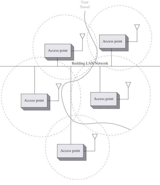
A solution is to place multiple wireless access points within the facility, as shown in Figure 11-11. Mobile clients will be able to maintain a connection as they travel through the workplace because the wireless client will automatically select the access point that provides the strongest signal level. The access points can be arranged so that overlapping coverage of the workplace is provided, thus enabling seamless roaming for the client. The signal coverage is shown in the shape of circles in Figure 11-11. In actual practice, the radiation patterns are highly irregular due to reflections of the transmitted signal.
It is important to verify that sufficient RF signal level is available for the users in the WLAN. This is best accomplished by performing a site survey. Inside a build-ing, a site survey is performed to determine the best location(s) for placing the access point(s) for providing maximum RF coverage for the wireless clients. Site surveys are also done with outside installations to determine the coverage area.
Bridge
PC PC
LAN Network–Bld #1
LAN Network–Bld #2 PC
PC PC
PC
Rooftop Antenna
Bridge
Site Survey
Performed to determine the best location(s) for placing the access point(s) to provide maximum RF coverage for the wireless clients
FIGURE 11-11 An example of configuring multiple access points to extend the range for wireless connectivity.
A site survey for indoor and outdoor installations should obtain the following key information:
Indoor
• Electrical power
• Wired network connection point(s) • Access point placement
• RF coverage—user mobility • Bandwidth supported
• identify any significant RF interference
Outdoor
• Electrical power (base access point) • Connection back to the home network
Section 11-3 • 802.11 WIRELESS NETWORKING 425
Access point Access point
Access point Access point
Access point User
Travel
• Antenna selection • Bandwidth supported • RF coverage
• Identify any significant RF interference
For example, a site survey was conducted to determine access point placement to provide wireless network connectivity for a building. The objective was to provide mobile client access throughout the building. The building already had two wired connections available for placing an access point. Figure 11-12 provides the floor plan for the building.
C
B
D A
1
2
= Ethernet CAT5e
FIGURE 11-12 The floor plan of the building being surveyed for a wireless LAN.
The available wired network connections are indicated in the drawing. The site survey began with placing an access point at position 1. A wireless mobile client was used to check the signal throughout the building. The wireless management software that came with the WLAN adapter was used to gather the test results.
The first measurement was taken at point A as shown in Figure 11-13. Notice that the data speed is 11 Mbps. This will change if the signal level decreases signifi-cantly. The wireless PCMCIA card also comes with a way to check the signal statis-tics as illustrated in Figure 11-14. This figure provides a plot of the signal quality, the missed access point (AP) beacons, transmit retries, the signal strength, and the trans-mit rate.
FIGURE 11-13 The RF signal level observed at point A.
Section 11-3 • 802.11 WIRELESS NETWORKING 427
FIGURE 11-14 The signal statistics from point A.
The next observation was made at point B. A signal level of “Good” and a trans-mit rate of 11 Mbps was observed. The signal has decreased somewhat, but the “Good” indicates that a connection is still available. Figure 11-15 shows the obser-vation made at point B. The signal level drops to “Fair” at point C as shown in Fig-ure 11-16.
The mobile client was moved to point D in the building, and a signal quality of “Out of range” was observed. This is also called a loss of association with the access point. Figure 11-17 shows the observed signal level.
FIGURE 11-15 The signal quality of “Good” at point B.
FIGURE 11-17 The “Out of range” measurement for point D.
The site survey shows that one access point placed at point 1 in the building is not sufficient to cover the building’s floor plan. The survey shows that the additional cost of another access point is easily justified for providing full building wireless LAN coverage. The building has two wired network connections available for plac-ing an access point (points 1 and 2). It was decided to place another access point at point 2. The site survey was repeated, and it showed that “Excellent” signal strength was obtained throughout the building. In some cases, a range extendercan be used to provide additional wireless coverage. This device basically extends the reach of the wireless network.
11-4
B
LUETOOTH
, W
I
MAX,
AND
RFID
This section looks at three different wireless technologies: Bluetooth, WiMAX, and RFID. Each of these technologies plays important roles in the wireless networks. The sections that follow examine each of these wireless technologies, including a look at configuration and examples of the hardware being used.
Bluetooth
This section examines another wireless technology called Bluetooth, based on the 802.15 standard. Bluetooth was developed to replace the cable connecting computers, mobile phones, handheld devices, portable computers, and fixed electronic devices. The information normally carried by a cable is transmitted over the 2.4 GHz ISM fre-quency band, which is the same frefre-quency band used by 802.11b/g/n. There are three output power classes for Bluetooth. Table 11-5 lists the maximum output power and the operating distance for each class.
TABLE 11-5 Bluetooth Output Power Classes
Power Class Maximum Output Power Operating Distance
1 20 dBm ~ 100 m
2 4 dBm ~ 10 m
3 0 dBm ~ 1 m
When a Bluetooth device is enabled, it uses an inquiry procedureto determine whether any other Bluetooth devices are available. This procedure is also used to al-low itself to be discovered.
If a Bluetooth device is discovered, it sends an inquiry reply back to the Blue-tooth device initiating the inquiry. Next, the BlueBlue-tooth devices enter the paging pro-cedure. The paging procedureis used to establish and synchronize a connection between two Bluetooth devices. When the procedure for establishing the connection has been completed, the Bluetooth devices will have established a piconet. A piconet is an ad hoc network of up to eight Bluetooth devices such as a computer, mouse, headset, earpiece, and so on. In a piconet, one Bluetooth device (the master) is re-sponsible for providing the synchronization clock reference. All other Bluetooth de-vices are called slaves.
The following is an example of setting up a Bluetooth network linking a Mac OS X computer to another Bluetooth enabled device. To enable Bluetooth on the Mac OS X, click Apple—Systems Preferences. Under hardware, select Bluetooth— Set-tings, and the window shown in Figure 11-18 is opened. Click theBluetooth Power
button to turn on Bluetooth. Click Discoverable. This enables other Bluetooth de-vices to find you.
Inquiry Procedure
Used by Bluetooth to discover other Bluetooth devices or to allow itself to be discovered
Paging Procedure
Used to establish and synchronize a connection between two Bluetooth devices
Piconet
An ad hoc network of up to eight Bluetooth devices
FIGURE 11-18 The window for configuring the Bluetooth settings.
In the next step you will select the device with which you will be establishing a Bluetooth connection. Select Devices—Set-up New Device—Turn Bluetooth On
if it is not already on. You will next be guided using the Bluetooth Setup Assistant
and will be asked to select the device type. You have the choice of connecting to a mouse, keyboard, mobile phone, printer, or other device. In this case,Other Device
is selected. This choice is selected when connecting to another computer. The Blue-tooth Device Setupwill search for another Bluetooth device. There will be a notifi-cation on the screen alerting you when another Bluetooth device is found. Select continue if this is the device you want to connect to. It is called pairingwhen another
Pairing
When a Bluetooth device is set up to connect to another Bluetooth device.
Bluetooth device is set up to connect to another Bluetooth device. You may be asked for a Passkey. The Passkeyis used in Bluetooth Security to limit outsider access to the pairing. Only people with the Passkey will be able to pair with your Bluetooth device.
At this point, you are now able to transfer files between the paired devices. This requires that the file exchange settings for the device have been set to allows files to come in. An example of the setup for the file transfer is shown in Figure 11-19.
Section 11-4 • Bluetooth, WiMAX, and RFID 431
Passkey
Used in Bluetooth Security to limit outsider access to the pairing
FIGURE 11-19 The window showing the settings for a file transfer.
The screen shown in Figure 11-20 shows an incoming text file. The File Trans-fer menu enables the user to select where received files are saved. In this case, the in-coming files are being saved to the desktop.
FIGURE 11-20 The window showing that a text file is coming in from another Bluetooth device.
This example has demonstrated setting up Bluetooth on a Mac OS X. The steps for setting up Bluetooth on a Windows XP or Vista computer or even a Blackberry differ slightly, but the basic steps are the same. The following are the basic steps you need to complete to pair with another Bluetooth device:
1. Enable the Bluetooth radio.
2. Enable Discoverability (this enables other Bluetooth devices to find you). 3. Select the device for pairing.
WiMAX
WiMAX(Worldwide Interoperability for Microwave Access) is a broadband wire-less system that has been developed for use as broadband wirewire-less access (BWA) for fixed and mobile stations and can provide a wireless alternative for last mile broad-band access in the 2 GHz to 66 GHz frequency range. BWA access for fixed stations can be up to 30 miles, whereas mobile BWA access is 3–10 miles. Internationally, the WiMAX frequency standard is 3.5 GHz while the United States uses both the unli-censed 5.8 GHz and the liunli-censed 2.5 GHz spectrum. There are also investigations with adapting WiMAX for use in the 700 MHz frequency range. Information trans-mitted at this frequency is less susceptible to signal blockage due to trees. The disad-vantage of the lower frequency range is the reduction in the bandwidth.
WiMAX uses Orthogonal Frequency Division Multiplexing (OFDM) as its sig-naling format. This sigsig-naling format was selected for the WiMAX standard IEEE 802.16a standard because of its improvedNLOS(non line-of-sight) characteristics in the 2 GHz to 11 GHz frequency range. An OFDM system uses multiple frequen-cies for transporting the data, which helps minimize multipath interference problems. Some frequencies may be experiencing interference problems, but the system can se-lect the best frequencies for transporting the data.
WiMAX also provides flexible channel sizes (for example, 3.5 MHz, 5 MHz, and 10 MHz), which provides adaptability to standards for WiMAX worldwide. This also helps ensure that the maximum data transfer rate is being supported. For exam-ple, the allocated channel bandwidth could be 6 MHz, and the adaptability of the WiMAX channel size allows it to adjust to use the entire allocated bandwidth.
Additionally, the WiMAX (IEEE 802.16e) media access control (MAC) layer differs from the IEEE 802.11 Wi-Fi MAC layer in that the WiMAX system has to compete only once to gain entry into the network. When a WiMAX unit has gained access, it is allocated a time slot by the base station, thereby providing the WiMAX with scheduled access to the network. The WiMAX system uses time division multi-plexing (TDM) data streams on the downlink and time-division multiple access (TDMA) on the uplink and centralized channel management to make sure time-ssitive data is delivered on time. Additionally, WiMAX operates in a collision-free en-vironment, which improves channel throughput.
WiMAX has a range of up to 31 miles, and it operates in both point-to-point and point-to-multipoint configurations. This can be useful in situations where DSL or cable network connectivity is not available. WiMAX is also useful for providing the last mile connection. Thelast mileis basically the last part of the connection from the telecommunications provider to the customer. The cost of the last mile connec-tion can be expensive, which makes a wireless alternative attractive to the customer. The 802.16e WiMAX standard holds a lot of promise for use as a mobile air in-terface. Another standard, 802.20, is a mobile air interface being developed for con-sumer use. This standard plans to support data rates over 1 Mbps, which is comparable to DSL and cable connections. Additional 802.20 is being developed to support high-speed mobility. In other words, the user could be in a fast car or train and still have network connectivity.
RFID (Radio Frequency Identification)
Radio Frequency Identification (RFID) is a technique that uses radio waves to track and identify people, animal, objects, and shipments. This is done by the princi-ple of modulated backscatter. The term “backscatter” is referring to the reflection of
WiMAX
A broadband wireless system based on the IEEE 802.16e standard
BWA
Broadband wireless access
NLOS
Non line-of-sight
Last Mile
The last part of the connection from the telecommunications provider to the customer
Radio Frequency Identification (RFID)
A technique that uses radio waves to track and identify people, animals, objects, and shipments
Backscatter
Refers to the reflection of the radio waves striking the RFID tag and reflecting back to the transmitter source
the radio waves striking the RFID tag and reflecting back to the transmitter source with its stored unique identification information.
Figure 11-21 illustrates the basic block for an RFID system.
Section 11-4 • Bluetooth, WiMAX, and RFID 433
Reader
(Transceiver)
(Transponder)
TAG
FIGURE 11-21 Basic block diagram of an RFID system.
The RFID system consists of two things:
• An RFID tag (also called the RF transponder) includes an integrated antenna and radio electronics.
• A reader (also called a transceiver) consists of a transceiver and an antenna. A transceiver is the combination of a transmitter and receiver.
The reader (transceiver) transmits radio waves, which activates (turns on) an RFID tag. The tag then transmits modulated data, containing its unique identification information stored in the tag, back to the reader. The reader then extracts the data stored on the RFID tag.
The RFID idea dates back to 1948, when the concept of using reflected power as a means of communication was first proposed. The 1970s saw further development in RFID technology, in particular, a UHF scheme that incorporates rectification of the RF signal for providing power to the tag. Development of RFID technology signifi-cantly increased in the 1990s. Applications included toll collection that allowed ve-hicles to pass through tollbooths at highway speeds while still being able to record data from the tag.
Today, RFID technology is being used to track inventory shipments for major commercial retailers, the transportation industries, and the Department of Defense. Additionally, RFID applications are being used in Homeland Security in tracking container shipments at border crossings. Additionally, RFID is being incorporated into wireless LAN (WLAN) computer networks to keep better track of inventory. Wireless technologies are becoming more important for the enterprise. RFID tech-nology is being used as a wireless means for asset tracking and as a result is placing more importance on its role in the network. The tracking technology is even being ex-tended to tracking WiFi devices within the WLAN infrastructure.
There are three parameters that define an RFID system. These include the following:
• Means of powering the tag • Frequency of operation
Powering the Tag RFID tags are classified in three ways based on how they ob-tain their operating power. The three different classifications are passive, semi-active, and active.
• Passive:Power is provided to the tag by rectifying the RF energy, transmitted from the reader, that strikes the RF tag antenna. The rectified power level is suf-ficient to power the ICs on the tags and also provides sufsuf-ficient power for the tag to transmit a signal back to the reader. Figure 11-22 shows an example of a passive RFID tag (also called an inlay).
The tag inlays include both the RFID chip and the antenna mounted on a sub-strate.
• Semi-active:The tags use a battery to power the electronics on the tag but use the property of backscatter to transmit information back to the reader.
• Active:Use a battery to power the tag and transmit a signal back to the reader. Basically this is a radio transmitter. New active RFID tags are incorporating wireless Ethernet, the 802.11b–WiFi connectivity. An example is the G2C501 Active RFID tag from G2 Microsystems shown in Figure 11-23. The power consumption of the G2C501 is 10µA in the sleep mode and uses two AA bat-teries with an expected lifetime of five years. The G2C501 also works in the standard 915 MHz range. The G2C501 also has location capability. This is ac-complished by making Receive Signal Strength Indicator (RSSI) measure-ments from three separate access points. The three measuremeasure-ments provide sufficient information to make a triangulation measurement for use in locating the object.
Antenna Integrated Circuit
Substrate
FIGURE 11-22 Examples of an RFID inlay.
FIGURE 11-23 The G2C501 Active RFID tag from G2Microsystems (courtesy of G2Microsystems).
Frequency of Operation The RFID tags must be tuned to the reader’s transmit frequency to turn on. RFID systems typically use three frequency bands for opera-tion, LF, HF, and UHF as shown in Figure 11-24:
• Low-frequency (LF)tags typically use frequency-shift keying (FSK) between the 125/134 kHz frequencies. The data rates from these tags is low (~12 kbps) and they are not appropriate for any applications requiring fast data transfers. However, the low-frequency tags are suitable for animal identification, such as dairy cattle and other livestock. The RFID tag information is typically obtained when the livestock are being fed. The read range for low-frequency tags is ap-proximately .33 meters.
• High-frequency (HF) tags operate in the 13.56 MHz industrial band. High-frequency tags have been available commercially since 1995. It is known that the longer wavelengths of the HF radio signal are less susceptible to absorption by water or other liquids. Therefore, these tags are better suited for tagging liquids. The read range for high-frequency tags is approximately 1 meter. The short read range provides for better defined read ranges. The applications for tags in this frequency range include access control, smart cards, and shelf inventory. • Ultra-high frequency (UHF)tags work at 860–960 MHz and at 2.4 GHz. The
data rates for these tags can be from 50–150 kbps and greater. These tags are popular for tracking inventory. The read range for passive UHF tags is 10–20 feet, which make it a better choice for reading pallet tags. However, if an active tag is used, a read range up to 100 meters is possible.
Section 11-5 • SECURING WIRELESS LANS 435
LF 125/134 kHz
HF 13.56 MHz
UHF 860 - 960 MHz
2.4 GHz
FIGURE 11-24 The frequency bands used by RFID tags.
Communications (Air Interface) Protocol The air interface protocol adopted for RFID tags is Slotted Aloha, a network communications protocol technique sim-ilar to the Ethernet protocol. In a Slotted Aloha protocol, the tags are only allowed to transmit at predetermined times after being energized. This technique reduces the chance of data collisions between RFID tag transmissions and allows for the reading of up to 1000 tags per second. (Note: This is for high-frequency tags). The operating range for RFID tags can be up to 30 meters. This means that multiple tags can be en-ergized at the same time, and a possible RF data collision can occur. If a collision oc-curs, the tag will transmit again after a random back-off time. The readers transmit continuously until there is no tag collision.
11-5
SECURING WIRELESS LANS
This section provides an overview of securing 802.11 wireless LANs. The network administrator must be aware of the security issues when configuring a wireless LAN. The fact is, RF (radio frequencies) will pass through walls, ceilings, and floors of a
Slotted Aloha
A wireless network communications protocol technique similar to the Ethernet protocol
building even with low signal power. Therefore, the assumption should never be made that the wireless data is confined to only the user’s area. The network administrator must assume that the wireless data can be received by an unintended user. In other words, the use of an unsecured wireless LAN is opening a potential threat to network security.
To address this threat to WLAN security, the network administrator must make sure the WLAN is protected by firewalls and intrusion detection (see Chapter 10), and most importantly the network administrator must make sure that the wireless security features are
TURNED ON!!!!!
This might seem to be a bold statement, but surprisingly enough, many WLANs are placed on a network without turning on available wireless security features. Many times the user in the WLAN assumes that no one would break into his or her com-puter because nothing important exists on the system. This may be true, but to an at-tacker, the user has one very important item, access to the wired network through an unsecured client.
WLANs use an SSID (service set identifier) to authenticate users, but the prob-lem is that the SSID is broadcast in radio link beacons about 10 times per second. In WLAN equipment, thebeaconsare transmitted so that a wireless user can identify an access point to connect to. The SSID can be turned off so it isn’t transmitted with a beacon, but it is still possible for the SSID to be obtained by packet sniffing. As noted previously,packet sniffingis a technique used to scan through unencrypted data packets to extract information. In this case, an attacker uses packet sniffing to extract the SSID from data packets. Disabling SSID broadcasting will make it so that most client devices (such as Windows PCs and laptops) won’t notice that the wireless LAN is present. This at least keeps “casual snoopers” off the network. Enterprise-grade ac-cess points implement multiple SSIDs, with each configured SSID having its own VLAN and wireless configuration. This allows the deployment of a common wire-less LAN infrastructure that supports multiple levels of security, which is important for some venues such as airports and hospitals (where there are both public and pri-vate users).
IEEE 802.11 supports two ways to authenticate clients: open and sharekey.
Open authentication basically means that the correct SSID is being used. In sharekey
authentication, a packet of text is sent by the access point to the client with the in-struction to encrypt the text and return it to the access point. This requires that wired equivalent privacy (WEP) be turned on. WEP is used to encrypt and decrypt wireless data packets. The exchange and the return of the encrypted text verifies that the client has the proper WEP key and is authorized to be a member of the wireless network. It is important to note that shared key authentication is extremely vulnerable. As a re-sult, it’s standard practice to avoid the use of shared key authentication. An example of the setting for WEP encryption is provided in Figure 11-25 (a and b). In Figure 11-25 (a), the user has the WEP options of disabled (No Privacy), 64-bit WEP (Pri-vacy), and 128-bit WEP (More Privacy). Figure 11-25 (b) shows the wireless secu-rity settings in Windows Vista. There are clearly more options, and these newer wireless security settings are discussed next.
There is some concern that WEP isn’t a strong enough encryption to secure a wireless network. There is published information about WEP vulnerabilities, but even with this, WEP does provide some basic security and is certainly better than operat-ing the network with no security.
Beacon
Used to verify the integrity of a wireless link
FIGURE 11-25 An example of setting WEP encryption on a wireless client.
An improvement with wireless security is provided with WPA and WPA2. WPAstands for Wi-Fi Protected Access, and it supports the user authentication pro-vided by 802.1x and replaces WEP as the primary way for securing wireless trans-fers. WPA2 is an improved version of WPA. The 802.1x standard enhances wireless security by incorporating authentication of the user. Cisco Systems uses an 802.1x authentication system called LEAP. In Cisco LEAP, the user must enter a password to access the network. This means that if the wireless client is being used by an unau-thorized user, the password requirement will keep the unauunau-thorized user out of the network.
WPA is considered to be a higher level of security for wireless systems. In the 802.1x system, a user requests access to the wireless network via an access point. The next step is for the user to be authenticated. At this point, the user can only send EAP messages. EAPis the Extensible Authentication Protocol and is used in both WAP and WAP2 by the client computer and the access point. The access point sends an EAP message requesting the user’s identity. The user (client computer) returns the identity information that is sent by the access point to an authentication server. The server will then accept or reject the user’s request to join the network. If the client is authorized, the access point will change the user (client’s) state to authorized. A Re-mote Authentication Dial-In User Service (RADIUS) service is sometimes used to provide authentication. This type of authentication helps prevent unauthorized users from connecting to the network. Additionally, this authentication helps to keep au-thorized users from connecting to rouge of unauau-thorized access points.
Another way to further protect data transmitted over a WLAN is to establish a VPN connection (see Chapter 8). In this way, the data is protected from an attacker. The following are basic guidelines for wireless security:
• Make sure the wireless security features are turned on. • Use firewalls and intrusion detection on your WLAN.
Section 11-5 • SECURING WIRELESS LANS 437
WPA
Wi-Fi Protected Access
EAP
Extensible Authentication Protocol
RADIUS
Remote Authentication Dial-In Service
(a)
FIGURE 11-26 The terrain profile of the area to be supported by the proposed point-to-multipoint wireless network.
• Improve authentication of the WLAN by incorporating 802.1x features. • Consider using third-party end-to-end encryption software to protect the data
that might be intercepted by an unauthorized user.
• Whenever possible, use encrypted services such as SSH and Secure FTP. The bottom line is that the choice of the level of security will be based on mul-tiple factors within the network. For example, what is the cost benefit ratio of in-creased security? How will incorporating or not incorporating inin-creased wireless security affect users? The network administrator and the overall management will have to make the final decision regarding wireless security before it is installed and the network becomes operational.
11-6
CONFIGURING A POINT-TO-MULTIPOINT
WIRELESS LAN: A CASE STUDY
This section presents an example of preparing a proposal for providing a point-to-multipoint wireless network for a company. The administrators for the company have decided that it would be beneficial to provide a wireless network connection for their employees back to the company’s network (home network). This example addresses the following issues:
1. Conducting an initial antenna site survey
2. Establishing a link from the home network to the distribution point 3. Configuring the multipoint distribution
4. Conducting an RF site survey for establishing a baseline signal level for the re-mote wireless user
5. Configuring the remote user’s installation
The objective is to establish a point-to-multipoint wireless network that pro-vides remote users with a wireless network connection. The remote users are to be at fixed locations within the proposed coverage area. A simple terrain profile of the pro-posed area is shown in Figure 11-26. The data rate for the wireless connection to re-mote users needs to be at least 2 Mbps.
Home Network
Proposed Antenna
Site Mountain
Range River
Valley
1 km
Section 11-6 • CONFIGURING A POINT-TO-MULTIPOINT WIRELESS LAN: A CASE STUDY 439
1. Antenna Site Survey
The proposed antenna site (see Figure 11-26) is on top of a hill approximately 1 kilo-meter (km) from the home network. A site survey provides the following information:
• The site has a tower that can be used to mount the wireless antenna.
• The site has a small building and available rack space for setting up the wire-less networking equipment.
• There is a clear view of the surrounding area for 6 km in every direction. • There is not an available wired network connection back to the home network.
The decision is made to use the proposed antenna site and set up an 11 Mbps wireless link back to the home network.
2. Establishing a Point-to-Point Wireless Link to the Home
Network
The cost is too high to put in a wired connection back to the home network; there-fore, it is decided to use a point-to-point 802.11 wireless link for the interconnection. This requires that antennas be placed at both the home network and the antenna site. A wireless bridge is used at each end of the point-to-point wireless link to intercon-nect the networks. The bridge will conintercon-nect to the wired home network and to the mul-tipoint distribution on the antenna site. Also each antenna will be outfitted with lightning arrestors to protect the electronics from any possible lightning strikes. Fig-ure 11-27 shows the proposed wireless connection.
FIGURE 11-27 The proposed point-to-point wireless link from the home network to the antenna site.
There are many manufacturers of antennas that support wireless networking, and there are many types of antenna that can be used. Antenna types from many man-ufacturers were investigated for possible use in the interconnection. Three possible antennas were selected for the wireless network, as outlined in Table 11-6.
CH 1 Uplink 11 Mbps Link
Wireless Bridge
Wireless Bridge
Yagi Antenna
Yagi Antenna
Home Network
FIGURE 11-28 Antenna radiation patterns for (a) omnidirectional, (b) Yagi, and (c) dish [parabolic reflector] antenna, and supports 11 Mbps up to 7.5 km from the antenna. The cost of the Yagi antenna is comparable to the omnidirectional antenna.
Antenna B, the directional Yagi, is selected for the point-to-point link. The an-tenna meets the distance requirement and also meets the 11 Mbps data rate require-ment. Antennas A and C were not selected for the following reasons:
• Antenna A—the omnidirectional radiation pattern is not appropriate
• Antenna C—the cost of a high gain dish antenna is not justified for the short distance
3–4. Configuring the Multipoint Distribution/Conducting an RF
Site Survey
At this point, an 11 Mbps wireless data link has been established with the home net-work. The next task is to configure the antenna site for multipoint distribution. It was previously decided that a 2 Mbps link would be adequate for the remote users, based on the data rate to be supported for the planned coverage area.
TABLE 11-6 Sample of 802.11b Wireless Antennas Range in Range in
Antenna Type Radiation km at km at
Pattern 2 Mbps 11 Mbps Costs
A. Omni Omnidirectional 7 2 Moderate
B. Yagi Directional 12 7.5 Moderate
C. Dish Highly directional 38 18 High
Antenna A has an omnidirectional radiation pattern. This means the antenna can receive and transmit signals in a 360-degree pattern. Figure 11-28 (a) shows the radiation pattern for an omnidirectional antenna. Antenna A supports a 2 Mbps data rate up to 7 km from the antenna and supports an 11 Mbps data rate at a maximum distance of 2 km. Table 11-6 also indicates that this antenna has a moderate cost.
Antenna B is a Yagi antenna with a directional radiation pattern as shown in Figure 11-28 (b). The Yagi antenna supports a 2 Mbps data rate for a maximum of 12 km.
Antenna C is a “dish” antenna or parabolic reflector. These antennas provide extremely high directional gain. In this example, the dish antenna supports 11 Mbps up to 18 km away and 2 Mbps up to 38 km away. The cost of the dish antenna can be quite high relative to the cost of the Yagi or omnidirectional antenna.
Section 11-6 • CONFIGURING A POINT-TO-MULTIPOINT WIRELESS LAN: A CASE STUDY 441 The site survey in step 1 showed that there is a clear view of the surrounding
area for 6 km in each direction. Antenna A (see Table 11-6) provides an omnidirec-tional radiation pattern for 7 km. This satisfies the coverage area and 2 Mbps data rate. Antenna A is mounted on the antenna site tower, connected to a lightning ar-restor and then connected to the output of a wireless bridge. An RF site survey of the planned coverage area is next done to verify the signal quality provided by the an-tenna selected. Measurements are made from multiple locations within the planned coverage area. All remote sites within 4 km of the distribution show a signal strength of “Excellent,” as shown in Figure 11-29.
FIGURE 11-29 The signal quality of “Excellent” measured for the multipoint distribution.
The signal quality drops to “Good” at 6 km at all surveyed remote locations ex-cept for one area that shows a “Poor.” The measurement for this site is provided in Figure 11-30. Apparently the signal is being affected by multipath distortion off a small lake area. A fix to this might be to move the antenna to a different height to min-imize reflection problems. An antenna at a different height will receive different re-flections and possibly less interference. In some cases antenna alignment can be changed to decrease the interference. A more costly solution is to add antenna “diversity.” Basically this means that multiple antennas are placed on the receiving tower, and the best signal is used for the connection.
FIGURE 11-30 The signal quality of “Poor” measured at the remote site near the lake.
5. Configuring the Remote Installations
The last task is to develop a configuration for the remote users. The antenna for each remote user only needs to be able to see the multipoint distribution antenna site. The requirements for the remote client are as follows:
• 2 Mbps data rate connection
• Directional antenna (Yagi) plus mount, lightning arrestor, wireless bridge Antenna B (see Table 11-6) is selected for the directional antenna. This antenna will provide sufficient RF signal level for the remote user. Each remote user will need a wireless bridge and a switch to connect multiple users. (Note that the bridge is set for a 2 Mbps data rate.) Figure 11-31 shows the setup for the remote user.
Wireless Bridge
Hub or Switch Lightening
Arrestor
Yagi Antenna PC
PC
PC
PC
FIGURE 11-31 The setup for the remote user in the proposed point-to-multipoint wireless network.
S
UMMARY
This chapter presented an overview of wireless networking. The fundamental concept and example networks were also presented. The vendors of wireless networking equipment have made them very easy to integrate into existing networks, but the reader must understand that the key objective of the network administrator is to pro-vide a fast, reliable, and secure computer network. Carelessly integrating wireless components into the network can easily compromise this objective. Students should understand the following from reading this chapter:
• The operating characteristics of the 802.11 wireless networks
• The purpose of access points, wireless LAN adapters, and wireless bridges • How to perform a basic site survey on a building
• How to configure the network for user mobility • How to plan multipoint wireless distribution
A final note: The new wireless networking technologies have greatly simplified planning and installation. Anytime you are working with RF (radio frequencies) there is a chance of unexpected interference and noise. A well-planned RF installation re-quires a study of all known interference and a search for any possible interference. An RF study will also include signal path studies that enable the user to prepare a well-thought-out plan and allow an excellent prediction of received signal level. The bottom line is to obtain support for conducting an RF study.
Q
UESTIONS AND
P
ROBLEMS
Section 11-2
1. List two advantages of wireless networking.
2. What are the three areas defined for the IEEE 802.11 standard? 3. What is an ad hoc network?
4. What is the purpose of an Extended Service Set?
5. What are the four physical layer technologies being used in 802.11 wireless networking?
6. Describe the frequency spectrum for the DSSS channels in 802.11b wireless networking.
7. Define a pseudorandom sequence as it applies to FHSS.
8. What must the FHSS transmitting and receiving units know to communicate? 9. What is the frequency range used by 802.11a, and what modulation technique
is used?
10. What is the maximum data rate for the following: a. 802.11b
b. 802.11a c. 802.11g d. 802.11n
11. Define MIMO as it applies to 802.11n.
12. What is the purpose of the power-save mode in 802.11n?
Section 11-3
13. What is the purpose of an access point?
14. How does the access point know if a wireless data packet is intended for its network?
15. What is an association, and what is its purpose? 16. Draw a picture of a point-to-point wireless connection. 17. Draw a picture of a point-to-multipoint wireless network.
18. What are the key issues to be obtained from conducting a site survey for each of the following?
a. indoor b. outdoor
Section 11-4
19. In what frequency band does Bluetooth operate?
20. How many output power classes does Bluetooth have? List the power level and the operating range for each class.
21. What is a piconet?
22. What is the purpose of the inquiry procedure in Bluetooth? 23. What is the purpose of the paging procedure in Bluetooth? 24. Define the term backscatter.
25. What are the three parameters that define an RFID system? 26. Explain how power is provided to a passive RFID tag. 27. Cite three advantages for using an active RFID tag.
28. What are the three frequency bands typically used for RFID tags? 29. What is the WiMax frequency standard for the United States? 30. Why was OFDM selected for WiMax?
31. How does WiMax differ from Wi-Fi?
Section 11-5
32. What is the most important thing to do if using a wireless network? 33. What is the purpose of wireless beacons?
34. What information can be obtained from a wireless beacon? 35. What is the purpose of WEP?
36. List four guidelines for wireless security.
37. Describe the steps used by WPA2 to authenticate a user. 38. What is a RADIUS server?
Section 11-6
39. What type of wireless connection is used to connect the home network to a mul-tipoint distribution site?
40. Use the Internet to find a source of omnidirectional and directional antennas for each of the following standards.
a. 802.11b b. 802.11a c. 802.11g d. 802.11n
Prepare a list of three manufacturers for each antenna type. Include cost figures.
Critical Thinking
41. A wireless network receiving site is experiencing occasional loss of signal due to interference. Discuss the steps you would take to correct this problem. 42. Prepare a memo to your supervisor explaining why it is important to run
en-cryption on your wireless network.