Controller
_ _ _ _ _ _ _ _ _ _ _ _ _ _ _ _ _ _ _ _ _ _ _ _ _ _ _ _ _ _ _ _ _ _ _ _ _ _ _ _ _ _ _ _ _ _ _ _ _ _ _ _ _ _ _ _ _ _ _ _ _ _ _ _
1 About this documentation _ _ _ _ _ _ _ _ _ _ _ _ _ _ _ _ _ _ _ _ _ _ _ _ _ _ _ _ _ _ _ _ _ _ _ _ _ _ _ 6 1.1 Document history _ _ _ _ _ _ _ _ _ _ _ _ _ _ _ _ _ _ _ _ _ _ _ _ _ _ _ _ _ _ _ _ _ _ _ _ _ _ _ _ _ _ _ _ 9 1.2 Conventions used _ _ _ _ _ _ _ _ _ _ _ _ _ _ _ _ _ _ _ _ _ _ _ _ _ _ _ _ _ _ _ _ _ _ _ _ _ _ _ _ _ _ _ _ 10 1.3 Terminology used _ _ _ _ _ _ _ _ _ _ _ _ _ _ _ _ _ _ _ _ _ _ _ _ _ _ _ _ _ _ _ _ _ _ _ _ _ _ _ _ _ _ _ _ 11 1.4 Definition of the notes used _ _ _ _ _ _ _ _ _ _ _ _ _ _ _ _ _ _ _ _ _ _ _ _ _ _ _ _ _ _ _ _ _ _ _ _ _ _ 12
2 Safety instructions _ _ _ _ _ _ _ _ _ _ _ _ _ _ _ _ _ _ _ _ _ _ _ _ _ _ _ _ _ _ _ _ _ _ _ _ _ _ _ _ _ _ _ _ 13 2.1 General safety instructions _ _ _ _ _ _ _ _ _ _ _ _ _ _ _ _ _ _ _ _ _ _ _ _ _ _ _ _ _ _ _ _ _ _ _ _ _ _ _ 15 2.2 Product-specific safety instructions _ _ _ _ _ _ _ _ _ _ _ _ _ _ _ _ _ _ _ _ _ _ _ _ _ _ _ _ _ _ _ _ _ _ 19 2.2.1 Panel Controller/HMI p300 and p500 _ _ _ _ _ _ _ _ _ _ _ _ _ _ _ _ _ _ _ _ _ _ _ _ _ _ _ _ _ 19 2.2.2 Controller c300 and p300 _ _ _ _ _ _ _ _ _ _ _ _ _ _ _ _ _ _ _ _ _ _ _ _ _ _ _ _ _ _ _ _ _ _ _ 19 2.2.3 Heatsink and GapPad strips for Controller 3200 C _ _ _ _ _ _ _ _ _ _ _ _ _ _ _ _ _ _ _ _ _ _ 20 2.2.4 I/O system 1000 _ _ _ _ _ _ _ _ _ _ _ _ _ _ _ _ _ _ _ _ _ _ _ _ _ _ _ _ _ _ _ _ _ _ _ _ _ _ _ _ 20 2.2.5 Voltage supply (24 V DC) of the Controllers _ _ _ _ _ _ _ _ _ _ _ _ _ _ _ _ _ _ _ _ _ _ _ _ _ 21 2.2.6 RJ45 plug connections _ _ _ _ _ _ _ _ _ _ _ _ _ _ _ _ _ _ _ _ _ _ _ _ _ _ _ _ _ _ _ _ _ _ _ _ _ 21 2.2.7 Optional capacitor pack (CAPS pack) _ _ _ _ _ _ _ _ _ _ _ _ _ _ _ _ _ _ _ _ _ _ _ _ _ _ _ _ _ 21 2.3 Notes on wiring according to EMC _ _ _ _ _ _ _ _ _ _ _ _ _ _ _ _ _ _ _ _ _ _ _ _ _ _ _ _ _ _ _ _ _ _ _ 22
3 Controller-based Automation: Central motion control _ _ _ _ _ _ _ _ _ _ _ _ _ _ _ _ _ _ _ _ _ _ _ _ 23
4 System structure _ _ _ _ _ _ _ _ _ _ _ _ _ _ _ _ _ _ _ _ _ _ _ _ _ _ _ _ _ _ _ _ _ _ _ _ _ _ _ _ _ _ _ _ _ 26 4.1 Engineering tools _ _ _ _ _ _ _ _ _ _ _ _ _ _ _ _ _ _ _ _ _ _ _ _ _ _ _ _ _ _ _ _ _ _ _ _ _ _ _ _ _ _ _ _ 27 4.2 Controller: The control centre of the Controller-based Automation _ _ _ _ _ _ _ _ _ _ _ _ _ _ _ _ _ 29 4.3 FAST Application Software _ _ _ _ _ _ _ _ _ _ _ _ _ _ _ _ _ _ _ _ _ _ _ _ _ _ _ _ _ _ _ _ _ _ _ _ _ _ _ 30 4.4 "Visualisation" application software _ _ _ _ _ _ _ _ _ _ _ _ _ _ _ _ _ _ _ _ _ _ _ _ _ _ _ _ _ _ _ _ _ _ 31 4.4.1 Sample topology 1: External monitor panel/display for cabinet controllers _ _ _ _ _ _ _ _ 32 4.4.2 Sample topology 2: Separate control and visualisation _ _ _ _ _ _ _ _ _ _ _ _ _ _ _ _ _ _ _ 33 4.4.3 Sample topology 3: Independent control and visualisation (CANopen) _ _ _ _ _ _ _ _ _ _ 34
5 Commissioning the controller _ _ _ _ _ _ _ _ _ _ _ _ _ _ _ _ _ _ _ _ _ _ _ _ _ _ _ _ _ _ _ _ _ _ _ _ _ 35 5.1 Identification _ _ _ _ _ _ _ _ _ _ _ _ _ _ _ _ _ _ _ _ _ _ _ _ _ _ _ _ _ _ _ _ _ _ _ _ _ _ _ _ _ _ _ _ _ _ _ 35 5.2 Control elements of the controllers _ _ _ _ _ _ _ _ _ _ _ _ _ _ _ _ _ _ _ _ _ _ _ _ _ _ _ _ _ _ _ _ _ _ 35 5.3 Starting the controller _ _ _ _ _ _ _ _ _ _ _ _ _ _ _ _ _ _ _ _ _ _ _ _ _ _ _ _ _ _ _ _ _ _ _ _ _ _ _ _ _ _ 36 5.4 Configuring the controller _ _ _ _ _ _ _ _ _ _ _ _ _ _ _ _ _ _ _ _ _ _ _ _ _ _ _ _ _ _ _ _ _ _ _ _ _ _ _ 38 5.4.1 Establishing an automatic dial-up connection _ _ _ _ _ _ _ _ _ _ _ _ _ _ _ _ _ _ _ _ _ _ _ _ 38 5.4.2 Entering the IP address of the controller _ _ _ _ _ _ _ _ _ _ _ _ _ _ _ _ _ _ _ _ _ _ _ _ _ _ _ 38 5.4.2.1 Cabinet Controller with external monitor panel (3231 C/3241 C) _ _ _ _ _ _ _ 39 5.4.2.2 Cabinet Controller without external monitor panel (c300/3221 C) _ _ _ _ _ _ 40 5.4.3 Specifying the IP address of the controller via file (optional) _ _ _ _ _ _ _ _ _ _ _ _ _ _ _ _ 41 5.4.4 Establishing Windows® CE access rights _ _ _ _ _ _ _ _ _ _ _ _ _ _ _ _ _ _ _ _ _ _ _ _ _ _ _ 42 5.4.4.1 Setting up Windows® CE users in »WebConfig« _ _ _ _ _ _ _ _ _ _ _ _ _ _ _ _ _ 42 5.4.5 Use your own background image (Windows® CE) _ _ _ _ _ _ _ _ _ _ _ _ _ _ _ _ _ _ _ _ _ _ 43 5.5 Reset Controller / Load Lenze standard setting _ _ _ _ _ _ _ _ _ _ _ _ _ _ _ _ _ _ _ _ _ _ _ _ _ _ _ _ 44 5.6 I/O system 1000 at the backplane bus of the Cabinet Controller _ _ _ _ _ _ _ _ _ _ _ _ _ _ _ _ _ _ _ 45 5.6.1 Configuring I/O modules at the backplane bus _ _ _ _ _ _ _ _ _ _ _ _ _ _ _ _ _ _ _ _ _ _ _ 45 5.6.2 Determining the topology of the I/O modules automatically _ _ _ _ _ _ _ _ _ _ _ _ _ _ _ _ 47 5.7 Tabs of the I/O modules at the backplane bus _ _ _ _ _ _ _ _ _ _ _ _ _ _ _ _ _ _ _ _ _ _ _ _ _ _ _ _ _ 48
_ _ _ _ _ _ _ _ _ _ _ _ _ _ _ _ _ _ _ _ _ _ _ _ _ _ _ _ _ _ _ _ _ _ _ _ _ _ _ _ _ _ _ _ _ _ _ _ _ _ _ _ _ _ _ _ _ _ _ _ _ _ _ _
6 Parameter setting using »WebConfig« _ _ _ _ _ _ _ _ _ _ _ _ _ _ _ _ _ _ _ _ _ _ _ _ _ _ _ _ _ _ _ _ _ 51 6.1 System structure _ _ _ _ _ _ _ _ _ _ _ _ _ _ _ _ _ _ _ _ _ _ _ _ _ _ _ _ _ _ _ _ _ _ _ _ _ _ _ _ _ _ _ _ _ 51 6.2 Parameter setting of the Controller _ _ _ _ _ _ _ _ _ _ _ _ _ _ _ _ _ _ _ _ _ _ _ _ _ _ _ _ _ _ _ _ _ _ 51 6.3 Online connection from the Engineering PC to the controller _ _ _ _ _ _ _ _ _ _ _ _ _ _ _ _ _ _ _ _ 52 6.3.1 Setting IP addresses on the Engineering PC (example: Windows® XP) _ _ _ _ _ _ _ _ _ _ _ 52 6.4 Start »WebConfig« _ _ _ _ _ _ _ _ _ _ _ _ _ _ _ _ _ _ _ _ _ _ _ _ _ _ _ _ _ _ _ _ _ _ _ _ _ _ _ _ _ _ _ 53 6.5 User interface of »WebConfig« _ _ _ _ _ _ _ _ _ _ _ _ _ _ _ _ _ _ _ _ _ _ _ _ _ _ _ _ _ _ _ _ _ _ _ _ _ 54 6.5.1 Device parameters of the controller _ _ _ _ _ _ _ _ _ _ _ _ _ _ _ _ _ _ _ _ _ _ _ _ _ _ _ _ _ 56 6.5.2 Diagnostic/device commands _ _ _ _ _ _ _ _ _ _ _ _ _ _ _ _ _ _ _ _ _ _ _ _ _ _ _ _ _ _ _ _ _ 57 6.5.3 Logbook _ _ _ _ _ _ _ _ _ _ _ _ _ _ _ _ _ _ _ _ _ _ _ _ _ _ _ _ _ _ _ _ _ _ _ _ _ _ _ _ _ _ _ _ _ 58 6.5.3.1 Structure of a logbook entry: example _ _ _ _ _ _ _ _ _ _ _ _ _ _ _ _ _ _ _ _ _ _ 58 6.5.3.2 Filter options _ _ _ _ _ _ _ _ _ _ _ _ _ _ _ _ _ _ _ _ _ _ _ _ _ _ _ _ _ _ _ _ _ _ _ _ 59 6.5.3.3 Time filter for the display of logbook entries _ _ _ _ _ _ _ _ _ _ _ _ _ _ _ _ _ _ 59 6.5.3.4 Saving log files with mains failure protection _ _ _ _ _ _ _ _ _ _ _ _ _ _ _ _ _ _ 60 6.5.3.5 Exporting logbook entries _ _ _ _ _ _ _ _ _ _ _ _ _ _ _ _ _ _ _ _ _ _ _ _ _ _ _ _ _ 60 6.5.4 Device commands _ _ _ _ _ _ _ _ _ _ _ _ _ _ _ _ _ _ _ _ _ _ _ _ _ _ _ _ _ _ _ _ _ _ _ _ _ _ _ 61 6.5.5 User management _ _ _ _ _ _ _ _ _ _ _ _ _ _ _ _ _ _ _ _ _ _ _ _ _ _ _ _ _ _ _ _ _ _ _ _ _ _ _ 61 6.5.6 General parameters _ _ _ _ _ _ _ _ _ _ _ _ _ _ _ _ _ _ _ _ _ _ _ _ _ _ _ _ _ _ _ _ _ _ _ _ _ _ 61 6.5.7 Parameters of the communication cards (MC cards) _ _ _ _ _ _ _ _ _ _ _ _ _ _ _ _ _ _ _ _ _ 62 6.5.8 Polling _ _ _ _ _ _ _ _ _ _ _ _ _ _ _ _ _ _ _ _ _ _ _ _ _ _ _ _ _ _ _ _ _ _ _ _ _ _ _ _ _ _ _ _ _ 62 6.5.9 Language selection _ _ _ _ _ _ _ _ _ _ _ _ _ _ _ _ _ _ _ _ _ _ _ _ _ _ _ _ _ _ _ _ _ _ _ _ _ _ _ 62 6.5.10 Parameter list buttons _ _ _ _ _ _ _ _ _ _ _ _ _ _ _ _ _ _ _ _ _ _ _ _ _ _ _ _ _ _ _ _ _ _ _ _ _ 62
7 Programming with the »PLC Designer« _ _ _ _ _ _ _ _ _ _ _ _ _ _ _ _ _ _ _ _ _ _ _ _ _ _ _ _ _ _ _ _ 63 7.1 System structure _ _ _ _ _ _ _ _ _ _ _ _ _ _ _ _ _ _ _ _ _ _ _ _ _ _ _ _ _ _ _ _ _ _ _ _ _ _ _ _ _ _ _ _ _ 64 7.2 Function blocks _ _ _ _ _ _ _ _ _ _ _ _ _ _ _ _ _ _ _ _ _ _ _ _ _ _ _ _ _ _ _ _ _ _ _ _ _ _ _ _ _ _ _ _ _ 65 7.3 Configuring and parameterising the controller using the control application _ _ _ _ _ _ _ _ _ _ _ _ 66 7.4 Controller c300/p300: Access to odd Controller addresses _ _ _ _ _ _ _ _ _ _ _ _ _ _ _ _ _ _ _ _ _ _ 67 7.5 Creating remanent variables (retain/persistent) _ _ _ _ _ _ _ _ _ _ _ _ _ _ _ _ _ _ _ _ _ _ _ _ _ _ _ 69 7.5.1 Storage of retain data on the SD card (only Controllers 3221 C/3231 C) _ _ _ _ _ _ _ _ _ _ 70
8 »Backup & Restore« (data backup/restore) _ _ _ _ _ _ _ _ _ _ _ _ _ _ _ _ _ _ _ _ _ _ _ _ _ _ _ _ _ _ 72
9 »EASY Starter - Application Loader« (data transfer) _ _ _ _ _ _ _ _ _ _ _ _ _ _ _ _ _ _ _ _ _ _ _ _ _ _ 73
10 UPS function (data backup in case of voltage failure) _ _ _ _ _ _ _ _ _ _ _ _ _ _ _ _ _ _ _ _ _ _ _ _ _ 74 10.0.1 Internal UPS (for Controllers without UPS connection) _ _ _ _ _ _ _ _ _ _ _ _ _ _ _ _ _ _ _ 74 10.0.2 External UPS (for Controllers 3241 C with UPS connection) _ _ _ _ _ _ _ _ _ _ _ _ _ _ _ _ _ 75 10.1 Storage of »VisiWinNET® Smart« visualisation data _ _ _ _ _ _ _ _ _ _ _ _ _ _ _ _ _ _ _ _ _ _ _ _ _ 76 10.2 Storage of retain/persistent variables of the PLC _ _ _ _ _ _ _ _ _ _ _ _ _ _ _ _ _ _ _ _ _ _ _ _ _ _ _ 77
11 RTC function (Real Time Clock) _ _ _ _ _ _ _ _ _ _ _ _ _ _ _ _ _ _ _ _ _ _ _ _ _ _ _ _ _ _ _ _ _ _ _ _ _ 78
12 Device replacement – replacing the Controller (in the event of service) _ _ _ _ _ _ _ _ _ _ _ _ _ _ _ 79 12.1 Removing the connected (defective) controller _ _ _ _ _ _ _ _ _ _ _ _ _ _ _ _ _ _ _ _ _ _ _ _ _ _ _ _ 80 12.2 Connecting the new controller/replacement device _ _ _ _ _ _ _ _ _ _ _ _ _ _ _ _ _ _ _ _ _ _ _ _ _ 81 12.3 Device replacement against an incompatible replacement device (exceptional case) _ _ _ _ _ _ _ 82 12.4 Undo update of data (exceptional case) _ _ _ _ _ _ _ _ _ _ _ _ _ _ _ _ _ _ _ _ _ _ _ _ _ _ _ _ _ _ _ _ 83
Contents
_ _ _ _ _ _ _ _ _ _ _ _ _ _ _ _ _ _ _ _ _ _ _ _ _ _ _ _ _ _ _ _ _ _ _ _ _ _ _ _ _ _ _ _ _ _ _ _ _ _ _ _ _ _ _ _ _ _ _ _ _ _ _ _
13 Remote maintenance and diagnostics _ _ _ _ _ _ _ _ _ _ _ _ _ _ _ _ _ _ _ _ _ _ _ _ _ _ _ _ _ _ _ _ _ 86 13.1 Status LEDs of the Controllers _ _ _ _ _ _ _ _ _ _ _ _ _ _ _ _ _ _ _ _ _ _ _ _ _ _ _ _ _ _ _ _ _ _ _ _ _ 87 13.1.1 Status LEDs of the Controller 3200 C _ _ _ _ _ _ _ _ _ _ _ _ _ _ _ _ _ _ _ _ _ _ _ _ _ _ _ _ _ 88 13.1.2 Status LEDs of the Controllers c300/p300 _ _ _ _ _ _ _ _ _ _ _ _ _ _ _ _ _ _ _ _ _ _ _ _ _ _ 89 13.1.3 Status LEDs of the Controllers p500 _ _ _ _ _ _ _ _ _ _ _ _ _ _ _ _ _ _ _ _ _ _ _ _ _ _ _ _ _ _ 90 13.2 Diagnostics via Telnet _ _ _ _ _ _ _ _ _ _ _ _ _ _ _ _ _ _ _ _ _ _ _ _ _ _ _ _ _ _ _ _ _ _ _ _ _ _ _ _ _ _ 91 13.2.1 »WebConfig« settings _ _ _ _ _ _ _ _ _ _ _ _ _ _ _ _ _ _ _ _ _ _ _ _ _ _ _ _ _ _ _ _ _ _ _ _ _ 92 13.3 Data transfer via FTP _ _ _ _ _ _ _ _ _ _ _ _ _ _ _ _ _ _ _ _ _ _ _ _ _ _ _ _ _ _ _ _ _ _ _ _ _ _ _ _ _ _ 94 13.3.1 FTP settings with the »WebConfig« _ _ _ _ _ _ _ _ _ _ _ _ _ _ _ _ _ _ _ _ _ _ _ _ _ _ _ _ _ _ 95 13.3.2 FTP and web settings in the Internet Explorer _ _ _ _ _ _ _ _ _ _ _ _ _ _ _ _ _ _ _ _ _ _ _ _ 96 13.4 Diagnostics with the logbook _ _ _ _ _ _ _ _ _ _ _ _ _ _ _ _ _ _ _ _ _ _ _ _ _ _ _ _ _ _ _ _ _ _ _ _ _ _ 98 13.4.1 Logbook query via »WebConfig« _ _ _ _ _ _ _ _ _ _ _ _ _ _ _ _ _ _ _ _ _ _ _ _ _ _ _ _ _ _ _ 99 13.4.2 Logbook parameters _ _ _ _ _ _ _ _ _ _ _ _ _ _ _ _ _ _ _ _ _ _ _ _ _ _ _ _ _ _ _ _ _ _ _ _ _ _ 100 13.5 Activate Windows® CE interface _ _ _ _ _ _ _ _ _ _ _ _ _ _ _ _ _ _ _ _ _ _ _ _ _ _ _ _ _ _ _ _ _ _ _ _ 101 13.5.1 Remote Display: Remote control of Controller via Internet or LAN _ _ _ _ _ _ _ _ _ _ _ _ _ 103 13.5.2 Virtual Network Computing (VNC) _ _ _ _ _ _ _ _ _ _ _ _ _ _ _ _ _ _ _ _ _ _ _ _ _ _ _ _ _ _ 104
14 Visualisation with »VisiWinNET®« _ _ _ _ _ _ _ _ _ _ _ _ _ _ _ _ _ _ _ _ _ _ _ _ _ _ _ _ _ _ _ _ _ _ _ 105 14.1 Visualisation on the Controller: Local and remote _ _ _ _ _ _ _ _ _ _ _ _ _ _ _ _ _ _ _ _ _ _ _ _ _ _ _ 106 14.2 System structure _ _ _ _ _ _ _ _ _ _ _ _ _ _ _ _ _ _ _ _ _ _ _ _ _ _ _ _ _ _ _ _ _ _ _ _ _ _ _ _ _ _ _ _ _ 107 14.3 Using the visualisation to access data of the control/parameters _ _ _ _ _ _ _ _ _ _ _ _ _ _ _ _ _ _ 108 14.4 Local visualisation with the "LogicAndMotionV3" direct driver _ _ _ _ _ _ _ _ _ _ _ _ _ _ _ _ _ _ _ _ 110
14.4.1 Selecting the target device using the Windows® CE operating system
(example 3200 C/p500) _ _ _ _ _ _ _ _ _ _ _ _ _ _ _ _ _ _ _ _ _ _ _ _ _ _ _ _ _ _ _ _ _ _ _ _ 111 14.4.2 Project Explorer _ _ _ _ _ _ _ _ _ _ _ _ _ _ _ _ _ _ _ _ _ _ _ _ _ _ _ _ _ _ _ _ _ _ _ _ _ _ _ _ 113 14.4.3 Using the variables browser to access variables _ _ _ _ _ _ _ _ _ _ _ _ _ _ _ _ _ _ _ _ _ _ _ 114 14.4.4 Accept variable definitions to project _ _ _ _ _ _ _ _ _ _ _ _ _ _ _ _ _ _ _ _ _ _ _ _ _ _ _ _ _ 116 14.4.5 Creating control elements/linking them to variables _ _ _ _ _ _ _ _ _ _ _ _ _ _ _ _ _ _ _ _ 117 14.4.6 Transferring an application to the target device _ _ _ _ _ _ _ _ _ _ _ _ _ _ _ _ _ _ _ _ _ _ _ 118 14.4.7 Start the »VisiWinNET®« _ _ _ _ _ _ _ _ _ _ _ _ _ _ _ _ _ _ _ _ _ _ _ _ _ _ _ _ _ _ _ _ _ _ _ 119 14.5 Remote access with the "LogicAndMotionV3" direct driver _ _ _ _ _ _ _ _ _ _ _ _ _ _ _ _ _ _ _ _ _ _ 120 14.6 OPC tunnel for local visualisation (integrated control system) _ _ _ _ _ _ _ _ _ _ _ _ _ _ _ _ _ _ _ _ 121 14.6.1 Integrating the OPC tunnel in »VisiWinNET®« _ _ _ _ _ _ _ _ _ _ _ _ _ _ _ _ _ _ _ _ _ _ _ _ 122 14.6.2 Browsing variable definitions _ _ _ _ _ _ _ _ _ _ _ _ _ _ _ _ _ _ _ _ _ _ _ _ _ _ _ _ _ _ _ _ _ 123 14.6.3 Manual integration of variables (experts only - background knowledge required!) _ _ _ _ 125 14.6.4 Configure OPC tunnel _ _ _ _ _ _ _ _ _ _ _ _ _ _ _ _ _ _ _ _ _ _ _ _ _ _ _ _ _ _ _ _ _ _ _ _ _ 128 14.7 OPC tunnel for external visualisation (remote access) _ _ _ _ _ _ _ _ _ _ _ _ _ _ _ _ _ _ _ _ _ _ _ _ 129 14.7.1 Windows® CE operating system _ _ _ _ _ _ _ _ _ _ _ _ _ _ _ _ _ _ _ _ _ _ _ _ _ _ _ _ _ _ _ 129 14.7.1.1 Configure OPC tunnel for remote access (Windows® CE) _ _ _ _ _ _ _ _ _ _ _ _ 130 14.7.2 Windows® XP/XP Embedded operating system _ _ _ _ _ _ _ _ _ _ _ _ _ _ _ _ _ _ _ _ _ _ _ 131 14.7.2.1 Configure OPC tunnel for remote access (Windows® XP/XP Embedded) _ _ _ 132 14.7.3 Browsing variable definitions _ _ _ _ _ _ _ _ _ _ _ _ _ _ _ _ _ _ _ _ _ _ _ _ _ _ _ _ _ _ _ _ _ 133 14.8 Lenze specifications _ _ _ _ _ _ _ _ _ _ _ _ _ _ _ _ _ _ _ _ _ _ _ _ _ _ _ _ _ _ _ _ _ _ _ _ _ _ _ _ _ _ _ 135 14.8.1 Install additional fonts _ _ _ _ _ _ _ _ _ _ _ _ _ _ _ _ _ _ _ _ _ _ _ _ _ _ _ _ _ _ _ _ _ _ _ _ _ 135 14.8.2 Timeout (waiting position) of the CAN OPC server influences the time response of the
_ _ _ _ _ _ _ _ _ _ _ _ _ _ _ _ _ _ _ _ _ _ _ _ _ _ _ _ _ _ _ _ _ _ _ _ _ _ _ _ _ _ _ _ _ _ _ _ _ _ _ _ _ _ _ _ _ _ _ _ _ _ _ _
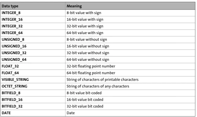
15 Parameter reference _ _ _ _ _ _ _ _ _ _ _ _ _ _ _ _ _ _ _ _ _ _ _ _ _ _ _ _ _ _ _ _ _ _ _ _ _ _ _ _ _ _ _ 136 15.1 Structure of the parameter description _ _ _ _ _ _ _ _ _ _ _ _ _ _ _ _ _ _ _ _ _ _ _ _ _ _ _ _ _ _ _ _ 137 15.1.1 Data types _ _ _ _ _ _ _ _ _ _ _ _ _ _ _ _ _ _ _ _ _ _ _ _ _ _ _ _ _ _ _ _ _ _ _ _ _ _ _ _ _ _ _ 137 15.1.2 Parameters with read access _ _ _ _ _ _ _ _ _ _ _ _ _ _ _ _ _ _ _ _ _ _ _ _ _ _ _ _ _ _ _ _ _ 138 15.1.3 Parameters with write access _ _ _ _ _ _ _ _ _ _ _ _ _ _ _ _ _ _ _ _ _ _ _ _ _ _ _ _ _ _ _ _ _ 138 15.1.3.1 Parameters with setting range _ _ _ _ _ _ _ _ _ _ _ _ _ _ _ _ _ _ _ _ _ _ _ _ _ _ 138 15.1.3.2 Parameters with selection list _ _ _ _ _ _ _ _ _ _ _ _ _ _ _ _ _ _ _ _ _ _ _ _ _ _ 138 15.1.3.3 Parameters with bit-coded setting _ _ _ _ _ _ _ _ _ _ _ _ _ _ _ _ _ _ _ _ _ _ _ _ 139 15.1.4 Parameter attributes _ _ _ _ _ _ _ _ _ _ _ _ _ _ _ _ _ _ _ _ _ _ _ _ _ _ _ _ _ _ _ _ _ _ _ _ _ _ 139 15.2 Basic parameters of the Controllers _ _ _ _ _ _ _ _ _ _ _ _ _ _ _ _ _ _ _ _ _ _ _ _ _ _ _ _ _ _ _ _ _ _ 140 15.3 Voltage buffering by external UPS (optional for Controller 3241 C) _ _ _ _ _ _ _ _ _ _ _ _ _ _ _ _ _ 170 15.4 Monitor panel (integrated/external) _ _ _ _ _ _ _ _ _ _ _ _ _ _ _ _ _ _ _ _ _ _ _ _ _ _ _ _ _ _ _ _ _ _ 173 15.5 PLC (Logic/Motion) _ _ _ _ _ _ _ _ _ _ _ _ _ _ _ _ _ _ _ _ _ _ _ _ _ _ _ _ _ _ _ _ _ _ _ _ _ _ _ _ _ _ _ 177 15.6 Backup & Restore _ _ _ _ _ _ _ _ _ _ _ _ _ _ _ _ _ _ _ _ _ _ _ _ _ _ _ _ _ _ _ _ _ _ _ _ _ _ _ _ _ _ _ _ 179 15.7 Ethernet _ _ _ _ _ _ _ _ _ _ _ _ _ _ _ _ _ _ _ _ _ _ _ _ _ _ _ _ _ _ _ _ _ _ _ _ _ _ _ _ _ _ _ _ _ _ _ _ _ 183 15.8 EtherCAT _ _ _ _ _ _ _ _ _ _ _ _ _ _ _ _ _ _ _ _ _ _ _ _ _ _ _ _ _ _ _ _ _ _ _ _ _ _ _ _ _ _ _ _ _ _ _ _ _ 185 15.9 CAN _ _ _ _ _ _ _ _ _ _ _ _ _ _ _ _ _ _ _ _ _ _ _ _ _ _ _ _ _ _ _ _ _ _ _ _ _ _ _ _ _ _ _ _ _ _ _ _ _ _ _ _ 190 15.9.1 Parameters of the first CAN interface _ _ _ _ _ _ _ _ _ _ _ _ _ _ _ _ _ _ _ _ _ _ _ _ _ _ _ _ _ 191 15.9.2 Parameters of the second CAN interface _ _ _ _ _ _ _ _ _ _ _ _ _ _ _ _ _ _ _ _ _ _ _ _ _ _ _ 193 15.10 PROFIBUS / PROFINET / Serial interfaces _ _ _ _ _ _ _ _ _ _ _ _ _ _ _ _ _ _ _ _ _ _ _ _ _ _ _ _ _ _ _ _ 196
Index _ _ _ _ _ _ _ _ _ _ _ _ _ _ _ _ _ _ _ _ _ _ _ _ _ _ _ _ _ _ _ _ _ _ _ _ _ _ _ _ _ _ _ _ _ _ _ _ _ _ _ 198 Your opinion is important to us _ _ _ _ _ _ _ _ _ _ _ _ _ _ _ _ _ _ _ _ _ _ _ _ _ _ _ _ _ _ _ _ _ _ _ _ _ 206
1
About this documentation
_ _ _ _ _ _ _ _ _ _ _ _ _ _ _ _ _ _ _ _ _ _ _ _ _ _ _ _ _ _ _ _ _ _ _ _ _ _ _ _ _ _ _ _ _ _ _ _ _ _ _ _ _ _ _ _ _ _ _ _ _ _ _ _
1
About this documentation
This documentation contains general information on how to parameterise, configure and diagnose the Lenze Controllers.
This documentation is part of the "Controller-based Automation" manual collection. It consists of the following sets of documentation:
Documentation type Subject
Product catalogue Controller-based Automation (system overview, sample topologies) Lenze Controller (product information, technical data)
System manuals Visualisation (system overview/sample topologies)
Communication manuals
Online helps Bus systems• Controller-based Automation EtherCAT® • Controller-based Automation CANopen® • Controller-based Automation PROFIBUS® • Controller-based Automation PROFINET®
Reference manuals
Online helps Lenze Controllers:• Controller 3200 C • Controller c300 • Controller p300 • Controller p500
software manuals
Online helps Lenze Engineering Tools:• »PLC Designer« (programming)
• »Engineer« (parameter setting, configuration, diagnostics) • »VisiWinNET® Smart« (visualisation)
_ _ _ _ _ _ _ _ _ _ _ _ _ _ _ _ _ _ _ _ _ _ _ _ _ _ _ _ _ _ _ _ _ _ _ _ _ _ _ _ _ _ _ _ _ _ _ _ _ _ _ _ _ _ _ _ _ _ _ _ _ _ _ _
More technical documentation for Lenze components
Further information on Lenze products which can be used in conjunction with Controller-based Automation can be found in the following sets of documentation:
Tip!Current documentation and software updates with regard to Lenze products can be found in the download area at:
www.lenze.com Target group
This documentation is intended for persons who commission and maintain a Controller-based automation system by means of a Lenze Controller and the »PLC Designer« engineering tool.
Screenshots/application examples
All screenshots in this documentation are application examples. Depending on the firmware
Planning / configuration / technical data Symbols:
Product catalogues
• Controller-based Automation • Controllers
• Inverter Drives/Servo Drives
Printed documentation
PDF file / online help in the Lenze engineering tool
Mounting & wiring Mounting instructions
• Controllers
• Communication cards (MC-xxx) • I/O system 1000 (EPM-Sxxx) • Inverter Drives/Servo Drives • Communication modules Hardware manuals
• Inverter Drives/Servo Drives
Sample applications/Using application templates
Online help/reference manuals
• i700 application sample • Application Samples 8400/9400
• FAST Application Template Lenze/PackML • FAST technology modules
Parameterisation, configuration, commissioning
Online help/reference manuals
• Controllers
• Inverter Drives/Servo Drives • I/O system 1000 (EPM-Sxxx) Online help/communication manuals
• Bus systems
1
About this documentation
_ _ _ _ _ _ _ _ _ _ _ _ _ _ _ _ _ _ _ _ _ _ _ _ _ _ _ _ _ _ _ _ _ _ _ _ _ _ _ _ _ _ _ _ _ _ _ _ _ _ _ _ _ _ _ _ _ _ _ _ _ _ _ _
Information regarding the validity
The information provided in this documentation is valid for the following Lenze Controllers:
Controllers Versions
Cabinet Controller
Example: Controller 3241 C with connected I/O system 1000
• Controller 3221 C • Controller 3231 C • Controller 3241 C
Example: Controller c300 with connected I/O system 1000
• Controller c300
Panel Controller
Example: Controller p500
• Controller p300 • Controller p500
1.1 Document history
_ _ _ _ _ _ _ _ _ _ _ _ _ _ _ _ _ _ _ _ _ _ _ _ _ _ _ _ _ _ _ _ _ _ _ _ _ _ _ _ _ _ _ _ _ _ _ _ _ _ _ _ _ _ _ _ _ _ _ _ _ _ _ _
1.1
Document history
Version Description
2.0 10/2015 TD17 Update for the Lenze automation system "Controller-based Automation" 3.11 • General corrections
• Chapter Safety instructions (13) extended • Chapter RTC function (Real Time Clock) (78) new • Chapter Parameter reference (136) extended
1.7 05/2015 TD17 Update for the "Controller-based Automation" 3.10 Lenze automation system • General corrections
• Chapter FAST Application Software (30)
• Chapter "Visualisation" application software (31)
1.6 01/2015 TD17 Update for the Lenze automation system "Controller-based Automation" 3.9 • Controller p300: C0427
• Chapter »Backup & Restore« (data backup/restore) (72)
• Chapter »EASY Starter - Application Loader« (data transfer) (73)
• Chapter Visualisation with »VisiWinNET®« (105)
1.5 04/2014 TD17 Update for the "Controller-based Automation" 3.8 Lenze automation system • Controller c300/p300
1.4 11/2012 TD11 Update for the Lenze automation system "Controller-based Automation" 3.6 • Controller c300/p300 added (in preparation)
1.3 05/2012 TD11 Update for the Lenze automation system "Controller-based Automation" 3.3 • Amended by Controllers p500 (panel controllers)
1.2 12/2011 TD11 Update for the Lenze automation system "Controller-based Automation" 3.2 1.1 04/2011 TD11 Revision on the Lenze automation system "Controller-based Automation" 3.1 1.0 10/2010 TD11 First edition on the Lenze automation system "Controller-based Automation" 3.x
1
About this documentation
1.2 Conventions used
_ _ _ _ _ _ _ _ _ _ _ _ _ _ _ _ _ _ _ _ _ _ _ _ _ _ _ _ _ _ _ _ _ _ _ _ _ _ _ _ _ _ _ _ _ _ _ _ _ _ _ _ _ _ _ _ _ _ _ _ _ _ _ _
1.2
Conventions used
This documentation uses the following conventions to distinguish between different types of information:
Type of information Highlighting Examples/notes
Spelling of numbers
Decimal separator Point The decimal point is always used. For example: 1234.56
Text
Program name » « »PLC Designer«...
Window italics The message window... / The Options dialog box ... Variable names Setting bEnable to TRUE...
Control element bold The OK button ... / The Copy command ... / The Properties tab ... / The Name input field ...
Sequence of menu
commands If several commands must be used in sequence to carry out a function, the individual commands are separated by an arrow. Select FileOpen to...
Shortcut <bold> Use <F1> to open the online help.
If a key combination is required for a command, a "+" is placed between the key identifiers: With <Shift>+<ESC>... Hyperlink underlined Reference to further information: Hyperlink to further
information. Icons
Page reference (10) Reference to further information: Page number in PDF file. Step-by-step instructions
1.3 Terminology used
_ _ _ _ _ _ _ _ _ _ _ _ _ _ _ _ _ _ _ _ _ _ _ _ _ _ _ _ _ _ _ _ _ _ _ _ _ _ _ _ _ _ _ _ _ _ _ _ _ _ _ _ _ _ _ _ _ _ _ _ _ _ _ _
1.3
Terminology used
Term Meaning
Controllers The Controller is the central component of the Lenze automation system which control the motion sequences by means of the application software.
The Controller communicates with the field devices (inverters) via the fieldbus. Engineering PC The Engineering PC and the Engineering tools installed serve to configure and
parameterise the system "Controller-based Automation".
The Engineering PC communicates with the controller via Ethernet.
Engineering tools Software solutions for easy engineering in all phases which serve to commission, configure, parameterise and diagnose the Lenze automation system.
Engineering tools (27)
FAST Feasibly Applicable Software Toolbox
FAST Application Software (30)
Fieldbus node Devices integrated in the bus system as, for instance, Controller and inverter Field device
Inverters Generic term for Lenze frequency inverters, servo inverters PLC Programmable Logic Controller
RTC RTC function (Real Time Clock) PLC Programmable Logic Controller (PLC) UPS Uninterruptible power system (UPS) Bus systems
CAN CAN (Controller Area Network) is an asynchronous, serial fieldbus system.
CANopen® is a communication protocol based on CAN. The Lenze system bus (CAN on board) operates with a subset of this communication protocol.
CANopen® is a registered community trademark of the CAN user organisation CiA® (CAN in Automation e. V.).
EtherCAT® (Ethernet for Controller and Automation Technology) is an Ethernet-based fieldbus system which fulfils the application profile for industrial real-time systems. EtherCAT® is a registered trademark and patented technology, licenced by Beckhoff Automation GmbH, Germany.
Ethernet specifies the software (protocols) and hardware (cables, plugs, etc.) for wired data networks. In the form of "Industrial Ethernet", the Ethernet standard is used in industrial production systems.
On the basis of IEEE 802.3, standard Ethernet is specified by the Institute of Electrical and Electronics Engineers (IEEE), USA.
PROFIBUS® (Process Field Bus) is a widely used fieldbus system for the automation of machines and production lines.
PROFIBUS® is a registered trademark and patented technology licensed by the PROFIBUS & PROFINET International (PI) user organisation.
PROFINET® (Process Field Network) is a real-time capable fieldbus system based on Ethernet.
PROFINET® is a registered trademark and patented technology licensed by the PROFIBUS & PROFINET International user organisation (PI).
1
About this documentation
1.4 Definition of the notes used
_ _ _ _ _ _ _ _ _ _ _ _ _ _ _ _ _ _ _ _ _ _ _ _ _ _ _ _ _ _ _ _ _ _ _ _ _ _ _ _ _ _ _ _ _ _ _ _ _ _ _ _ _ _ _ _ _ _ _ _ _ _ _ _
1.4
Definition of the notes used
The following signal words and symbols are used in this documentation to indicate dangers and important information:
Safety instructions
Layout of the safety instructions:
Application notes
Pictograph and signal word!
(characterise the type and severity of danger)
Note
(describes the danger and gives information about how to prevent dangerous situations)
Pictograph Signal word Meaning
Danger! Danger of personal injury through dangerous electrical voltageReference to an imminent danger that may result in death or serious personal injury if the corresponding measures are not taken.
Danger! Danger of personal injury through a general source of dangerReference to an imminent danger that may result in death or serious personal injury if the corresponding measures are not taken.
Stop! Danger of property damageReference to a possible danger that may result in property damage if the corresponding measures are not taken.
Pictograph Signal word Meaning
Note! Important note to ensure trouble-free operation
Tip! Useful tip for easy handling_ _ _ _ _ _ _ _ _ _ _ _ _ _ _ _ _ _ _ _ _ _ _ _ _ _ _ _ _ _ _ _ _ _ _ _ _ _ _ _ _ _ _ _ _ _ _ _ _ _ _ _ _ _ _ _ _ _ _ _ _ _ _ _
2
Safety instructions
Please observe the safety instructions in this documentation when you want to commission an automation system or a plant with a Lenze Controller.
The device documentation contains safety instructions which must be observed!Read the documentation supplied with the components of the automation system carefully before you start commissioning the Controller and the connected devices. Please pay special attention to Product-specific safety instructions (19) in this documentation!
Danger!
High electrical voltage
Injury to persons caused by dangerous electrical voltage
Possible consequences
Death or severe injuries
Protective measures
Switch off the voltage supply before working on the components of the automation system.
After switching off the voltage supply, do not touch live device parts and power terminals immediately because capacitors may be charged.
Observe the corresponding information plates on the device.
Danger!
Injury to persons
Risk of injury is caused by ...
• unpredictable motor movements (e.g. unintended direction of rotation, too high velocities or jerky movement);
• impermissible operating states during the parameterisation while there is an active online connection to the device.
Possible consequences
Death or severe injuries
Protective measures
• If required, provide systems with installed inverters with additional monitoring and protective devices according to the safety regulations valid in each case (e.g. law on
2
Safety instructions
_ _ _ _ _ _ _ _ _ _ _ _ _ _ _ _ _ _ _ _ _ _ _ _ _ _ _ _ _ _ _ _ _ _ _ _ _ _ _ _ _ _ _ _ _ _ _ _ _ _ _ _ _ _ _ _ _ _ _ _ _ _ _ _
Stop!
Damage or destruction of machine parts
Damage or destruction of machine parts can be caused by ... • Short circuit or static discharges (ESD);
• unpredictable motor movements (e.g. unintended direction of rotation, too high velocities or jerky movement);
• impermissible operating states during the parameterisation while there is an active online connection to the device.
Protective measures
• Always switch off the voltage supply before working on the components of the automation system.
• Do not touch electronic components and contacts unless ESD measures were taken beforehand.
• If required, provide systems with installed inverters with additional monitoring and protective devices according to the safety regulations valid in each case (e.g. law on technical equipment, regulations for the prevention of accidents).
2.1 General safety instructions
_ _ _ _ _ _ _ _ _ _ _ _ _ _ _ _ _ _ _ _ _ _ _ _ _ _ _ _ _ _ _ _ _ _ _ _ _ _ _ _ _ _ _ _ _ _ _ _ _ _ _ _ _ _ _ _ _ _ _ _ _ _ _ _
2.1
General safety instructions
Scope
The following general safety instructions apply to the Lenze drive and automation components. Please pay special attention to Product-specific safety instructions (19) in this documentation!
Also for your own safety
• Lenze drive and automation components ... ... must only be used as directed;
... must never be commissioned if they display signs of damage; ... must never be technically modified;
... must never be commissioned if they are not fully mounted; ... must never be operated without the required covers;
... can have live, moving and rotating parts during and after operation, depending on their degree of protection. Surfaces can be hot.
• Lenze drive and automation components ... ... only use the accessories approved;
... only use original manufacturer spare parts.
• Observe all specifications contained in the enclosed documentation and related documentation.
This is the condition for safe and troublefree operation and the achievement of the specified product features.
The specifications, processes, and circuitry described in this document are for guidance only and must be adapted to your own specific application. Lenze does not take responsibility for the suitability of the process and circuit proposals.
• Only qualified personnel may work with and on Lenze drive and automation components. According to IEC 60364 or CENELEC HD 384 these are persons who ...
... are familiar with installing, mounting, commissioning, and operating the device; ... have the corresponding qualifications for their work;
... know and can apply all regulations for the prevention of accidents, directives, and laws applicable on site.
Danger!
If the following basic safety measures are disregarded, severe injuries to persons and damage to material assets may result.
2
Safety instructions
2.1 General safety instructions
_ _ _ _ _ _ _ _ _ _ _ _ _ _ _ _ _ _ _ _ _ _ _ _ _ _ _ _ _ _ _ _ _ _ _ _ _ _ _ _ _ _ _ _ _ _ _ _ _ _ _ _ _ _ _ _ _ _ _ _ _ _ _ _
Transport, storage
Transport and storage of the Lenze drive and automation components in a dry, low-vibration environment without aggressive atmosphere, preferably in the packaging provided by the manufacturer. If required, use carrying aids for transport.
• Protect devices against dust and impacts.
• Observe climatic conditions according to the "Operating conditions" section in the "Technical data" chapter of the product catalogue.
• Printed-circuit boards, such as communication cards (MC-Cards), ... ... may only be transported and stored in ESD packaging;
... may only be touched at contact-free positions;
... may only be positioned on suitable underlays (e.g. on ESD packaging or conductive foamed material).
Mechanical installation
• Install the Lenze drive and automation components according to the instructions given in the corresponding documentation.
Select the mounting location so that the "Operating conditions" in the "Technical data" chapter of the product catalogue are guaranteed.
• In the installation space, continuous and sufficient air circulation is absolutely required to dissipate the heat of the device. The ventilation slots must not be covered.
• Provide for careful handling and avoid mechanical overload. During handling neither bend components, nor change the insulation distances.
• The devices contain electrostatic sensitive devices that can be easily damaged by short circuit or static discharge (ESD). Thus, only touch electronic components and contacts if ESD measures were taken before.
• The fixing rail and the mounting plate in the control cabinet have to be conductive and free of lacquer. The mechanical connections have to be ensured.
2.1 General safety instructions
_ _ _ _ _ _ _ _ _ _ _ _ _ _ _ _ _ _ _ _ _ _ _ _ _ _ _ _ _ _ _ _ _ _ _ _ _ _ _ _ _ _ _ _ _ _ _ _ _ _ _ _ _ _ _ _ _ _ _ _ _ _ _ _
Electrical installation
• The electrical installation must be carried out according to the appropriate regulations (e.g. cable cross-sections, fuses, PE connection).
Additional information can be obtained from the documentation.
• When working on live components, applicable national regulations (e.g. BGV 3) must be observed.
• The documentation includes notes about wiring according to EMC regulations (shielding, earthing, filters and cable routing). The compliance with limit values required in conjunction with the EMC legislation is the responsibility of the manufacturer of the machine or system.
Warning: The Lenze drive and automation components can be used in industrial environments according to EN 61000-6-4. These devices can cause radio interferences in residential areas. In this case, protective measures may be required.
Notes on wiring according to EMC (22)
• If specified in the technical data, the components must be installed in housings (e.g. control cabinets) to meet the limit values for radio interferences valid at the site of installation. The housings must enable an EMC-compliant installation. Observe in particular that e.g. the control cabinet doors should have a circumferential metal connection to the housing.
Reduce housing openings and cutouts to a minimum.
• All pluggable connection terminals must only be connected or disconnected when no voltage is applied.
Commissioning
If required, provide systems with additional monitoring and protective devices according to the safety regulations (e.g. law on technical equipment, regulations for the prevention of accidents).
Maintenance and servicing
• The Lenze drive and automation components are maintenance-free. Nonetheless, you have to carry out a visual inspection at regular and sufficiently short intervals considering the ambient conditions.
Check the following:
• Does the environment still meet the operating conditions specified in the "Technical data" chapter of the product catalogue?
• Is the heat dissipation impeded by dust or dirt?
• Are the mechanical and electrical connections still okay?
• If the ambient air is polluted, the cooling surfaces may become dirty or the air vents may be obstructed. Therefore, clean the cooling surfaces and air vents periodically under these operating conditions. Do not use sharp or pointed tools for this purpose!
• Heatsinks get very hot during operation.
Before working on the devices, check the heatsink temperature.
Flammable material or substances must not be placed near the heatsink or get to it. • After disconnecting the system from the supply voltage, do not touch live device parts and
2
Safety instructions
2.1 General safety instructions
_ _ _ _ _ _ _ _ _ _ _ _ _ _ _ _ _ _ _ _ _ _ _ _ _ _ _ _ _ _ _ _ _ _ _ _ _ _ _ _ _ _ _ _ _ _ _ _ _ _ _ _ _ _ _ _ _ _ _ _ _ _ _ _
Cleaning
• Deenergise the complete system before cleaning. • Heatsinks get very hot during operation.
Before working on the devices, check the heatsink temperature.
• The Lenze drive and automation components can be damaged if they are not appropriately cleaned.
Housings will get scratched or dull if cleaning agents containing alcohol, solvents or abrasives are used.
Electrical components will be damaged if humidity enters in the housing. • Wipe the housing using a clean, lintfree, soft cloth.
• For stubborn dirt, only use water and an ordinary household cleaning agent or a detergent declared especially for flat screens.
Do not spray the detergent directly on the device. Moisten the cloth only slightly with the detergent.
Disposal
Recycle or dispose of the Lenze drive and automation components according to the applicable regulations.
2.2 Product-specific safety instructions
_ _ _ _ _ _ _ _ _ _ _ _ _ _ _ _ _ _ _ _ _ _ _ _ _ _ _ _ _ _ _ _ _ _ _ _ _ _ _ _ _ _ _ _ _ _ _ _ _ _ _ _ _ _ _ _ _ _ _ _ _ _ _ _
2.2
Product-specific safety instructions
2.2.1
Panel Controller/HMI p300 and p500
• When selecting the installation site, be sure to observe an ergonomic position of the screen and pay regard to the incidence of light, which may cause reflections on the screen.
Protect the device from direct sunlight since the housing may heat up strongly.
• During installation, there is a danger that the controller will fall out of the mounting cutout. You should therefore secure it to prevent this happening until all screw clamps have been fitted. • During mounting, the gasket of the front frame is exposed and can be damaged.
Check the gasket to make sure it is undamaged before you install the device. Handle the gasket with care during mounting.
Protect the gasket from UV radiation.
• The device must be securely seated in the mounting cutout and the front panel seal must be correctly fitted. Otherwise, class of protection IP65 will not be achieved on the front side of the device! (IP rating is not UL-approved.)
• A touchscreen does not comply with the Ergonomics Directive ZH 1/618. This is why it is only designed for shorttime inputs and control functions. For longer
inputs, connect an external keyboard.
2.2.2
Controller c300 and p300
Stop!
Depending on the system, sporadic cycle time extensions beyond the set cycle time or jitters may occur.
Especially the use of the engineering tools »EASY Starter«, »Engineer«, »WebConfig« and an online change or data access may cause such a cycle time extension and may only be effected in a machine-safe state.
2
Safety instructions
2.2 Product-specific safety instructions
_ _ _ _ _ _ _ _ _ _ _ _ _ _ _ _ _ _ _ _ _ _ _ _ _ _ _ _ _ _ _ _ _ _ _ _ _ _ _ _ _ _ _ _ _ _ _ _ _ _ _ _ _ _ _ _ _ _ _ _ _ _ _ _
2.2.3
Heatsink and GapPad strips for Controller 3200 C
[2-1] Heatsink and GapPad strips on the rear side of the Controller 3200 C
• The heatsink on the rear side of the Controller gets very hot during operation. Before working on the device, check the heatsink temperature.
Flammable material or substances must not be placed near the heatsink or get to it.
• On the rear side of the Controller, there are two GapPad strips. These strips serve to thermally connect the device to the DIN rail. If the strips are defective, they must be replaced.
Mounting of the device on the DIN rail is limited to 20 plug cycles. Afterwards, you have to exchange the GapPad strips (Lenze order number: EPCZMEG).
2.2.4
I/O system 1000
• Attach and detach Controllers and modules of the I/O system 1000 only when the supply voltage is switched off. Otherwise, they could be damaged by short circuits.
• Always arrange the modules from left to right starting with the Controller directly followed by a power supply module EMPS701 on the right side.
• The module must always be installed directly next to each other. Free slots between the modules are not permissible because otherwise the backplane bus would be interrupted. • The side contacts of the last module always must be covered with the supplied contact cover.
Otherwise, the modules may be damaged by short circuit or static discharge.
• In connection with the bus coupler module EPM-S130 (EtherCAT), only I/O compound modules EPM-Sxxx from hardware version 1B are supported.
Heatsink
2.2 Product-specific safety instructions
_ _ _ _ _ _ _ _ _ _ _ _ _ _ _ _ _ _ _ _ _ _ _ _ _ _ _ _ _ _ _ _ _ _ _ _ _ _ _ _ _ _ _ _ _ _ _ _ _ _ _ _ _ _ _ _ _ _ _ _ _ _ _ _
2.2.5
Voltage supply (24 V DC) of the Controllers
• The voltage input is not fused internally. The Controller can be destroyed when the input voltage is too high.
Observe the maximum possible input voltage.
Professionally fuse the device on the input side against voltage fluctuations and voltage peaks. • The Controller starts as soon as the supply voltage is applied. After the operating system has
been shut down, the controller switches off automatically. For restarting, the supply voltage has to be disconnected for a short time.
• In the event of an error, the device must be switched to a deenergised state immediately. For this, disconnect the supply connector and a possibly available UPS pack. Afterwards, send the device to the manufacturer. The address can be found on the back cover of this documentation. Please use the original packaging for the return!
2.2.6
RJ45 plug connections
If the RJ45 plug connection is exposed to oscillating or vibrating stress: • Use a strain relief in the immediate vicinity of the RJ45 socket.
• Select the contact surface on which the device is mounted as fixing point of the strain relief. • Comply with the related minimum bending radius of the cable used.
2.2.7
Optional capacitor pack (CAPS pack)
• Connect the capacitor pack before switching on the Controller.
• The Controller is only deenergised if the supply cable and the capacitor pack connecting cable have been disconnected.
• The capacitor pack is only deenergised if its capacitors are discharged.
2
Safety instructions
2.3 Notes on wiring according to EMC
_ _ _ _ _ _ _ _ _ _ _ _ _ _ _ _ _ _ _ _ _ _ _ _ _ _ _ _ _ _ _ _ _ _ _ _ _ _ _ _ _ _ _ _ _ _ _ _ _ _ _ _ _ _ _ _ _ _ _ _ _ _ _ _
2.3
Notes on wiring according to EMC
General information
• The electromagnetic compatibility of the system depends on the type of installation and care taken. Especially consider the following:
• Setup • Shielding • Earthing
• For diverging installations, the conformity to the CE EMC Directive requires a check of the system regarding the EMC limit values.
This is valid, for instance, when unshielded cables are used.
• The compliance of the EMC Directive is in the responsibility of the user.
If you observe the following measures, you can assume that the machine will operate without any EMC problems and that compliance with the EMC Directive and the EMC law is achieved. If devices which do not comply with the CE requirement concerning noise immunity EN 61000-6-2 are operated close to the system, these devices may be electromagnetically affected by the system.
Setup
• Provide electrical contact between the DIN rail and the earthed mounting plate:
Mounting plates with conductive surfaces (zinc-coated, stainless steel) allow permanent contact.
Painted plates are not suitable for an EMC-compliant installation. • If you use several mounting plates:
Connect as much surface of the mounting plates as possible (e.g. with copper strips). • Install data cables separately from the mains cables.
• Lay the cables as close as possible to the reference potential; freely suspended cables act like aerials.
Shielding
• If possible, only use cables with braided shield.
• The overlap rate of the shield should be higher than 80%.
• For data cables for serial connection, always use metal or metallised connectors. Connect the shield of the data cable to the connector shell.
Earthing
• Earth all metallically conductive components using suitable cables connected to a central earthing point (PE bar).
• Maintain the minimum cross-sections prescribed in the safety regulations:
_ _ _ _ _ _ _ _ _ _ _ _ _ _ _ _ _ _ _ _ _ _ _ _ _ _ _ _ _ _ _ _ _ _ _ _ _ _ _ _ _ _ _ _ _ _ _ _ _ _ _ _ _ _ _ _ _ _ _ _ _ _ _ _
3
Controller-based Automation: Central motion control
The Lenze automation system "Controller-based Automation" serves to create complex automation solutions with central motion control. Here, the Controller is the control centre of the system.
System structure of the Controller-based Automation
3
Controller-based Automation: Central motion control
_ _ _ _ _ _ _ _ _ _ _ _ _ _ _ _ _ _ _ _ _ _ _ _ _ _ _ _ _ _ _ _ _ _ _ _ _ _ _ _ _ _ _ _ _ _ _ _ _ _ _ _ _ _ _ _ _ _ _ _ _ _ _ _ Lenze provides especially coordinated system components:
• Engineering software
The Engineering tools (27) on your Engineering PC (Windows®) operating system ) serve to parameterise, configure and diagnose the system. The Engineering PC communicates with the Controller via Ethernet.
The Lenze engineering tools are available for download at:
www.lenze.comDownloadSoftware Downloads
• Controllers
The Lenze Controller is available as Panel Controller with integrated touch display and as Cabinet Controller in control cabinet design.
Cabinet Controllers provide a direct coupling of the I/O system 1000 via the integrated backplane bus.
• Bus systems
EtherCAT is the standard "on-board" bus system of the Controller-based Automation. EtherCAT enables the control of all nodes on one common fieldbus.
Optionally, CANopen, PROFIBUS and PROFINET can be used as extended topologies.
The controllers c300/p300 are also provided with an "on board" CANopen interface (in addition to EtherCAT).
• Inverter (e.g. Servo-Inverter i700)
"Application software" of the Lenze Controllers
The "Application Software" of the Lenze Controllers enables the control and/or visualisation of motion sequences.
FAST technology modules provide for an easy development of a modular machine control in the »PLC Designer«.
The following "Application Software" versions are available: • "FAST Runtime"
The sequence control takes place (by logically combined control signals) in the Controller. The motion control takes place in the inverter.
• "FAST Motion"
The sequence control and the motion control take place in the controller. The inverter merely serves as actuating drive.
Motion applications make special demands on the cycle time and real-time capability of the bus system between the Controller and the subordinate fieldbus nodes. This is the case, for instance, if the nodes are to be traversed in a synchronised way or position setpoints are to be transferred.
• "Visualisation"
The optional visualisation of the automation system can be used separately or additionally to "FAST Runtime" or "FAST Motion".
For this purpose, an external monitor panel/display can be connected to the Cabinet Controller 3231 C/3241 C.
_ _ _ _ _ _ _ _ _ _ _ _ _ _ _ _ _ _ _ _ _ _ _ _ _ _ _ _ _ _ _ _ _ _ _ _ _ _ _ _ _ _ _ _ _ _ _ _ _ _ _ _ _ _ _ _ _ _ _ _ _ _ _ _
Fieldbus communication
The Lenze controllers have different interfaces for fieldbus communication:
1) Only the master functionality is supported.
2) Up to release 3.9: "EL 100 CAN" driver / from release 3.10: "Lenze CAN driver"
The Ethernet interface serves to connect the Engineering PC or to create line topologies (no integrated switch for Controller c300/p300).
Range Cabinet Controller Panel Controller c300 3221 C 3231 C 3241 C p300 p500 Interfaces (on board)
Ethernet 1 2 1 2
EtherCAT 1 1) 1 1 1) 1
CANopen 1 - 1 2)
-Optional interfaces (communication cards)
CANopen MC-CAN2 - - 2) PROFIBUS master MC-PBM - - PROFIBUS slave MC-PBS - - PROFINET device MC-PND - - Ethernet MC-ETH - - Serial interfaces MC-ISI - -
4
System structure
_ _ _ _ _ _ _ _ _ _ _ _ _ _ _ _ _ _ _ _ _ _ _ _ _ _ _ _ _ _ _ _ _ _ _ _ _ _ _ _ _ _ _ _ _ _ _ _ _ _ _ _ _ _ _ _ _ _ _ _ _ _ _ _
4
System structure
This chapter provides you with an overview of the basic system structure of the Lenze "Controller-based Automation" system. The system consists of an Engineering PC, a Controller and the devices communicating with the Controller via the fieldbus.
[4-1] * The PROFIBUS fieldbus driver can only be accessed via PLC (Logic/Motion). Access via »EASY Starter« and »VisiWinNET®« is not provided.
Controllers and field devices form the automation system to be commissioned via the Engineering PC. The Engineering PC is a PC/Laptop with Windows® operating system and network connection. The Engineering PC comes installed with the Lenze Engineering tools (27) for parameter setting, configuration, programming and diagnostics.
The central control unit is the Controller with the PLC (Logic/Motion), consisting of the FAST Application Software (30)) with the running PLC application.
Device-internally, the Controller comes with a data manager for configuring and managing the data of the automation system. The data manager and the fieldbus driver enable the PLC (Logic/Motion) to access the system components and the field devices (inverter).
The fieldbus enables the Controller to read and write the parameters of the connected field devices.
4.1 Engineering tools
_ _ _ _ _ _ _ _ _ _ _ _ _ _ _ _ _ _ _ _ _ _ _ _ _ _ _ _ _ _ _ _ _ _ _ _ _ _ _ _ _ _ _ _ _ _ _ _ _ _ _ _ _ _ _ _ _ _ _ _ _ _ _ _
4.1
Engineering tools
The Engineering PC is a PC/Laptop with Windows® operating system and network connection. The Engineering PC comes installed with the Lenze Engineering tools which enable the desired automation solution to be ...
• parameterise/configure; • program;
4
System structure
4.1 Engineering tools
_ _ _ _ _ _ _ _ _ _ _ _ _ _ _ _ _ _ _ _ _ _ _ _ _ _ _ _ _ _ _ _ _ _ _ _ _ _ _ _ _ _ _ _ _ _ _ _ _ _ _ _ _ _ _ _ _ _ _ _ _ _ _ _
»EASY Navigator«: Starting the suitable Engineering tool
The Lenze Engineering software consists of the Engineering tools optimised for the respective Engineering stage.
The »EASY Navigator« represents the Lenze Engineering tools installed on the Engineering PC. Start the desired Engineering tool via the corresponding button:
The »EASY Navigator« ...
• simplifies the selection of the Engineering tool, depending on the Engineering phase. • simplifies starting the desired Engineering tool (depending on the application case). • makes it possible to select the Engineering tool suitable for the Engineering phase. The overview displays the respective function of the Engineering tools:
What would you like to do? Button Engineering tool Programming
• Program the controller
• Parameterise/commission the Servo-Inverter i700 • Parameterise the I/O system 1000
»PLC Designer«
Parameterising/configuring the inverter
• Parameterising and configuring the automation/drive system
• Parameterising Inverter Drives 8400/Servo Drives 9400
»Engineer«
Visualisation
• Visualising the applications of the automation system • Creating the visualisation/user interfaces
»VisiWinNET®«
Online diagnostics
• Easy online diagnostics of the controllers (from »EASY Starter« V1.2) and other Lenze devices
»EASY Starter« (reading parameters)
Online parameterisation
• Online parameterisation/commissioning of Lenze devices
• Direct online parameterisation when the online connection to the Lenze devices is active.
»EASY Starter« (reading/writing parameters)
Loading data into the Controller
• Load PLC programs, parameter sets and application data (LFL file) into the Controller.
»EASY Starter« Application Loader
Engineering tools that are not included in the »EASY Navigator«: Controller parameterisation/diagnostics
4.2 Controller: The control centre of the Controller-based Automation
_ _ _ _ _ _ _ _ _ _ _ _ _ _ _ _ _ _ _ _ _ _ _ _ _ _ _ _ _ _ _ _ _ _ _ _ _ _ _ _ _ _ _ _ _ _ _ _ _ _ _ _ _ _ _ _ _ _ _ _ _ _ _ _
4.2
Controller: The control centre of the Controller-based Automation
Cabinet controllers: Compact control cabinet design
Cabinet controllers are designed for the demanding continuous use in industrial applications. Compared to panel controllers, they are not equipped with an integrated display. The Controllers 3231 C and 3241 C are provided with a DVI interface for the connection of an external monitor panel.
Mounting is carried out in a control cabinet or a corresponding built-in housing on a standard DIN rail (35 mm).
The device-internal backplane bus provides for a direct connection of the I/O system 1000.
Panel controllers: controlling and visualising
Panel controllers are designed for the installation into control cabinets, machine panels, or other mounting cutouts. They are equipped with rear bolts and clamping screws which provide for easy mounting and reliable sealing (front panel enclosure IP65/rear panel IP20) in rough industrial environments. They can be operated easily by directly touching the screen.
From Lenze control technology release 3.10 onwards, the Panel Controllers are provided with PDF viewer, WordPad text editor, Microsoft® Office viewer and web browser. These tools can be executed from the desktop.
Product catalogue for the ControllerHere, further information on the device-specific features and technical data can be found.
4
System structure
4.3 FAST Application Software
_ _ _ _ _ _ _ _ _ _ _ _ _ _ _ _ _ _ _ _ _ _ _ _ _ _ _ _ _ _ _ _ _ _ _ _ _ _ _ _ _ _ _ _ _ _ _ _ _ _ _ _ _ _ _ _ _ _ _ _ _ _ _ _
4.3
FAST Application Software
By default, the FAST Application Software is installed in the Lenze Controller as "FAST Runtime" with
"FAST Motion" mode for the central control of PLC applications.
"FAST Motion" enables an extensive motion control of motion functions. Then inverter then only acts as an actuating drive.
For Panel Controllers, the "Visualisation" mode is available in addition, enabling a central visualisation with the Controller.
The application software consists of: • Windows® CE operating system
• Application Software "FAST Runtime" with "FAST Motion" for controlling motion sequences via standardised "FAST technology modules"
• Optional visualisation software (»VisiWinNET®« Compact CE).
Differences between "FAST Runtime" and "FAST Motion"
FAST Runtime
(formerly "L-force Logic" (LPC 1000)) FAST Motion(formerly "L-force Motion" (MPC 1000)) The Controller controls simple motion sequences by
logically combined control signals. The controller controls extensive motion sequences.The "FAST Motion" application software... • contains the PLCopen library;
• supports "SoftMotion" applications Logic applications are suitable for the control of inverters
without a Motion functionality which ... • execute simple motion sequences; • can only be controlled via PLC functionality.
Motion applications are suitable...
• for the control of inverters executing complex motion sequences of multi-axes in several dimensions; • ...for the control of devices that are to traverse
synchronously;
• for the transfer of setpoints.
Note!
FAST Motion in case of Controller c300 and p300
• The Motion Control libraries are not loaded by default into the library manager. • FAST Motion for "Coordinated Motion" (Robot kinematics) and axis groups are not
supported.
Fieldbus communication
Depending on the application software (FAST Runtime/Motion) used, a fieldbus for a Lenze device series can only be used in a limited way.
Details can be found in the communication manuals: • Controller-based Automation EtherCAT®
• Controller-based Automation CANopen® • Controller-based Automation PROFIBUS®
4.4 "Visualisation" application software
_ _ _ _ _ _ _ _ _ _ _ _ _ _ _ _ _ _ _ _ _ _ _ _ _ _ _ _ _ _ _ _ _ _ _ _ _ _ _ _ _ _ _ _ _ _ _ _ _ _ _ _ _ _ _ _ _ _ _ _ _ _ _ _
4.4
"Visualisation" application software
Engineering tool required: »VisiWinNET®«
The "Visualisation" application software extends the Controller to be a visualisation device and thus provides for a central visualisation of the system.
The visualisation can either run on a separate Controller or monitor panel or parallel to the "Runtime" or "Motion" application software on the Controller.
Various options described in the following sections are available for the communication link.
Note!
4
System structure
4.4 "Visualisation" application software
_ _ _ _ _ _ _ _ _ _ _ _ _ _ _ _ _ _ _ _ _ _ _ _ _ _ _ _ _ _ _ _ _ _ _ _ _ _ _ _ _ _ _ _ _ _ _ _ _ _ _ _ _ _ _ _ _ _ _ _ _ _ _ _
4.4.1
Sample topology 1: External monitor panel/display for cabinet controllers
[4-2] Sample topology: Controller 3231 C with an external monitor panel (connected to the DVI interface)
This topology with regard to its performance corresponds to the implemented solution (control/ visualisation on the same controller). The external monitor panel/display shows the visualisation.
Advantages
• Small amount of cabling • Protected operating conditions • Extensible topology
4.4 "Visualisation" application software
_ _ _ _ _ _ _ _ _ _ _ _ _ _ _ _ _ _ _ _ _ _ _ _ _ _ _ _ _ _ _ _ _ _ _ _ _ _ _ _ _ _ _ _ _ _ _ _ _ _ _ _ _ _ _ _ _ _ _ _ _ _ _ _
4.4.2
Sample topology 2: Separate control and visualisation
[4-3] Sample topology: Controller 3200 C as gateway for the Visualisation Controller (IPC)
The Visualisation Controller (IPC) accesses the field devices via the Controller 3200 C as gateway. In order to separate the control and visualisation, the integrated gateway function of the controller can be used.
The use of this topology is advisable... • to achieve a higher performance;
• for the use of different operating systems within one automation system. Engineering tools required: »EASY Starter«, »Engineer«
Advantages
• Several visualisations can access the controller. • Most suitable for extensive visualisation processes.
4
System structure
4.4 "Visualisation" application software
_ _ _ _ _ _ _ _ _ _ _ _ _ _ _ _ _ _ _ _ _ _ _ _ _ _ _ _ _ _ _ _ _ _ _ _ _ _ _ _ _ _ _ _ _ _ _ _ _ _ _ _ _ _ _ _ _ _ _ _ _ _ _ _
4.4.3
Sample topology 3: Independent control and visualisation (CANopen)
[4-4] Sample configuration: Parallel access of Controller 3200 C and Visualisation Controller (IPC)
If this topology is used, the Controller 3200 C and the Visualisation Controller (IPC) access the fieldbus independently of each other.
Advantages
• Spatially separate control and visualisation.
• The visualisation has access to the parameters of the field devices.
Disadvantage
• The visualisation may disrupt the real-time capability of the fieldbus. This topology therefore is only suitable for Motion systems to a limited extent (depending on the bus system used).
Note!
The configuration with a control and configuration independent of each other is only available for the CANopen bus system!
• CANopen enables (several) fieldbus master independent of each other.
5.1 Identification
_ _ _ _ _ _ _ _ _ _ _ _ _ _ _ _ _ _ _ _ _ _ _ _ _ _ _ _ _ _ _ _ _ _ _ _ _ _ _ _ _ _ _ _ _ _ _ _ _ _ _ _ _ _ _ _ _ _ _ _ _ _ _ _
5
Commissioning the controller
This chapter provides some general information on the commissioning of a controller. Depending on the actual hardware installed, different settings are required for integrating the controller into a network.
5.1
Identification
Every controller is provided with a nameplate containing the device data. The device data are helpful for identifying the technical equipment of the controller. Detailed information relating to the nameplate data can be found in the product catalogue for the Controller.
Web-based diagnostics/parameter setting
Via »WebConfig« the configuration of the controller can be identified. The parameter values of the controller can be represented using the web browser.
Online connection from the Engineering PC to the controller (52)
Assigning a unique name to the controller
In order to be able to clearly identify a Controller, the desired name has to be assigned for parameter 13 "System identification: Name" C0013. The assigned name can then be used in the corresponding engineering tool (e.g. »PLC Designer«) to identify the Controller.
5.2
Control elements of the controllers
Depending on the type and equipment, the Lenze Controllers are provided with various control elements (e.g. function keys for external monitor panels) and status LEDs for diagnostic purposes.
Status LEDs of the Controllers (87)
The controllers can be operated via external input devices (keyboard/mouse). This makes it possible to carry out comprehensive diagnostics and configuration tasks directly on the controller.
Note!
Please observe the predefined IP address of the controller for the initial commissioning:
192.168.5.99 (Lenze setting).
Further information on how to set the IP address of the Controller can be found here:
5
Commissioning the controller
5.3 Starting the controller
_ _ _ _ _ _ _ _ _ _ _ _ _ _ _ _ _ _ _ _ _ _ _ _ _ _ _ _ _ _ _ _ _ _ _ _ _ _ _ _ _ _ _ _ _ _ _ _ _ _ _ _ _ _ _ _ _ _ _ _ _ _ _ _
5.3
Starting the controller
The internal flash memory and the SD card are the storage media of the controller.
The operating system of the Controller and the FAST Application Software (30) are stored in the internal flash memory.
The SD card is used as memory for the following application data: • PLC boot project
• "Application Credit" for the FAST Application Software (30)
• Visualisation
• Databases of the data manager • prestart.txt/poststart.txt • Retain and logbook data
• User data (projects and individual data)
The combination of control technology software and application data on the SD card ensures that the data match the prevailing application in the present version.
The SD card serves to easily exchange data in a different device. This serves to avoid automatic, possibly unwanted and difficult-to-master update/downgrade processes.
How to change the SD card:1. For unlocking the SD card, push in lightly and then release.
Note!
All Controllers only work with a plugged-in SD card!
During the starting process of the controller
If a non-bootable USB flash drive is connected during the starting sequence, it will be stopped!
• Remove the USB stick and restart the Controller.
• Alternatively, the USB stick can be prepared using the »Backup & Restore« software. Further information can be found in the online help of the »Backup & Restore« software.
When the controller is running
Removal of the SD card will lead to a system failure!
• The SD card must not be removed while the controller is running (no "Hot Plugging" of the SD card possible).
• The SD card is required for the system start since it contains the system files for the starting process.
5.3 Starting the controller
_ _ _ _ _ _ _ _ _ _ _ _ _ _ _ _ _ _ _ _ _ _ _ _ _ _ _ _ _ _ _ _ _ _ _ _ _ _ _ _ _ _ _ _ _ _ _ _ _ _ _ _ _ _ _ _ _ _ _ _ _ _ _ _
IP configuration
The Controller has the preset standard IP address 192.168.5.99. The preset IP configuration can be changed in the »WebConfig«.
Setting IP addresses on the Engineering PC (example: Windows® XP) (52)
Entering the IP address of the controller (38)
After 15 seconds, the network configuration dialog box will close automatically; the controller continues with the starting process.
Error case: Controller does not start
If the Controller does not start, you can activate the Lenze standard setting with the reset button.
How to activate the Lenze standard setting:1. Switch off voltage supply. 2. Press Reset button.
3. Switch on the voltage supply while the Reset button is pressed and keep the Reset button pressed for at least 10 s.
• If the Error-LED is blinking (green/red) after this action, switch off the voltage supply again.
• The Controller must be disconnected from the mains until all LEDs have gone off. • Then switch on the voltage supply again.
5
Commissioning the controller
5.4 Configuring the controller
_ _ _ _ _ _ _ _ _ _ _ _ _ _ _ _ _ _ _ _ _ _ _ _ _ _ _ _ _ _ _ _ _ _ _ _ _ _ _ _ _ _ _ _ _ _ _ _ _ _ _ _ _ _ _ _ _ _ _ _ _ _ _ _
5.4
Configuring the controller
This chapter provides information on how to configure the Controller during initial commissioning. The IP address setting is preserved after a restart of the system.
5.4.1
Establishing an automatic dial-up connection
Further information on how to establish an automatic dial-up connection, remote maintenance and diagnostics options can be found under:
Remote maintenance and diagnostics (86)
In order to carry out a remote maintenance on the controller different mechanisms are provided:
Diagnostics via Telnet (91)
Data transfer via FTP (94)
Activate Windows® CE interface (101)
Diagnostics with the logbook (98)
5.4.2
Entering the IP address of the controller
The controller has the following network settings by default:
During initial commissioning of the Controller, the desired IP address has to be entered. Optionally, the network settings can be selected via a file:
Specifying the IP address of the controller via file (optional) (41)
Address Lenze setting IP address 192.168.5.99
Subnetwork 255.255.255.0
5.4 Configuring the controller
_ _ _ _ _ _ _ _ _ _ _ _ _ _ _ _ _ _ _ _ _ _ _ _ _ _ _ _ _ _ _ _ _ _ _ _ _ _ _ _ _ _ _ _ _ _ _ _ _ _ _ _ _ _ _ _ _ _ _ _ _ _ _ _
5.4.2.1
Cabinet Controller with external monitor panel (3231 C/3241 C)
Tip!Connect a keyboard to the Controller to be able to enter the IP address. Then you can make the entries:
[5-1] IP settings of the controller by default
• Start the control panel with <Shift+F4>.
• Start the network connections by double-click and enter the IP address, subnet mask, and the default gateway.
• After clicking the button the IP address is saved and need not be entered again when the system is restarted.
Note!
If an external display (monitor panel) is used, the switch-on sequence of display/ controller must be observed so that it can be correctly controlled by the controller:
• Connect the external display to the DVI output of the controller and switch it on before switching on the controller.
After connection of a monitor panel/an external display to a running controller, the display resolution is VGA .
• Calibrate the monitor panel/ display connected, so that the screen content can be displayed correctly.