THEORETICAL RESEARCHES ON THE FORCES AND STRESSES IN
COUPLING DEVICES - REVIEW
MIRCEA D.I.1), DAVID L1), PARASCHIV G.1), BIRIŞ S.ŞT.1), VLĂDUŢ V.2), GRIGORE I.2),
MAICAN E.1), UNGUREANU N.1), GĂGEANU I.2)
1)P.U. Bucharest;2)INMA Bucharest E-mail: [email protected] Keywords:coupling, tractor aggregate, trailer, system force
ABSTRACT
This paper presents a synthesis of theoretical researches carried out in Romania and worldwide on forces and stresses in coupling devices.
INTRODUCTION
Tractor-trail aggregates considered "slow vehicles", given their share of road traffic, to travel to and from the workplace and transport agricultural products and materials, is an impediment in ensuring fluency on public roads. To this is added the fact that agricultural machinery have often exceeded gauge.
To increase traffic safety in Romania were introduced strict regulations on the access to public roads of road vehicles of any type, based, mainly, on European Union directives (EU/EEC) and ECE – UN regulations which refer, to the same extent, to tractors, agricultural trailers and machines.
Thus, tractors, their trailers and agricultural machines, when in traffic on public roads in Romania are considered road vehicles, like cars, trucks, buses, trolleybuses, etc. and must satisfy the technical requirements imposed for the vehicle category they are part of.
Shapes, sizes, location and other technical characteristics of towing devices for caravans and light trailers are presented in the literature.
These devices are intended for trailers of categories O1 (one axle trailers, other than semi, with maximum mass not exceeding 0.75 t) and O2(trailers with maximum mass lower than 3,500 kg, except for trailers in category O1).
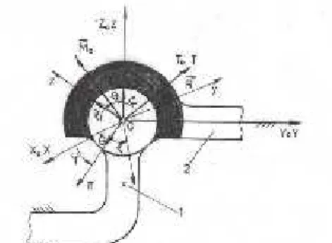
All couplings for these trailers are of ball bolt-type having spherical joint at the upper part and, at the lower part, the bolt attached to the tractor (Fig. 1). The centre of the spherical joint should be at a height between 350 mm and 420 mm from the road surface, the tractor being loaded.
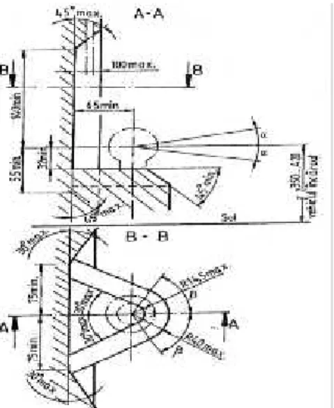
The coupling device fitted to the trailer drawbar must be located at a height of 430 ± 35 mm, the trailer being loaded with the maximum laden mass and placed on a horizontal surface. The spherical joint which is mounted on the tractor must be positioned so that a free space would remain around it (the unshaded space in Figure 2) allowing:
coupling and uncoupling the trailer at angles in the vertical and horizontal plane ofmin.= 10° respectivelymin.= 60°;
Fig. 1. Form and size of spherical joint mounted on the tractor
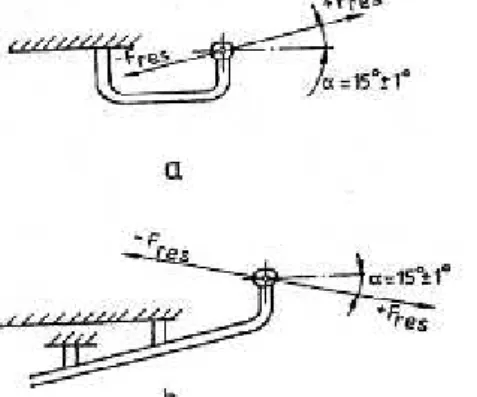
The coupling mounted on trailer drawbar is tested to dynamic and static stresses. It was found that a dynamic test with a force of magnitude of 0.6 F, at an angle of = -15° (fig. 3), in a plane passing through the centre of the spherical joint and parallel to the longitudinal plane of the vehicle, allows verifying simultaneously both the latching mechanism and the mechanical resistance of drawbar coupling head; it was considered that this method can also guarantee the reliability of the coupling head.
The test force must have a variation approximately sinusoidal, be applied with a frequency of more than 35 Hz, and the number of cycles must be 2 x 10⁶.
Fig. 3. Loading of coupling device mounted on drawbar
Fig. 2. Free spaces imposed around spherical joint mounting
Throughout the test, the towing device on drawbar and its components must not present cracks, tears, visible external damage or residual deformations.
For static tests, the towing device on drawbar is rigidly fixed and spherical joint bolt is stressed perpendicular to the drawbar axle with a force equal to the trailer mass in newtons(mrx 10); load should be increased progressively in 10 seconds, after which it is
maintained other 10 seconds. During the test, the spherical joint must get out of its place, and the coupling device must not suffer any kind of damage or residual deformation.
The drawbar is made of steel; if it has a welded construction, steel with a carbon percentage of 0.22% at the most, having guaranteed weldability, is used. Drawbar resistance is verified only by calculating it at static bending stress. The loading scheme and the calculation method are detailed in the literature.
If the centre of the spherical joint is below the plane passing through the highest device attachment point to the vehicle (fig. 4, a), then the force must be inclined by angle = +15°±1°; otherwise, when the centre of the spherical joint is above the plan already mentioned, the test is performed at an angle= -15°±1° (fig. 4, b).
Fig. 4. Loading of spherical joint device:a– spherical joint below the plan of attachment to the vehicle;b- spherical joint above the plan of attachment to the vehicle
MATERIAL AND METHOD
When determining the forces of stresses in coupling devices it must be taken into account the shape, size and technical conditions imposed to their aggregation devices.
Thus for each type of coupling system the legislation (directives, regulations, standards, etc.), stipulates the conditions they must meet and comply with.
RESULTS
To perform agricultural works an aggregate tractor-trailer is necessary (tractor-agricultural machine). Aggregation of tractor and trailer ((tractor-agricultural machine) is made with the help of coupling / drawbar. The analysis of the system of forces acting on the tractor-trailer aggregate [1] must take into account the system of forces acting on the aggregate, namely the mechanical conditions of such an aggregate must be established; mechanical conditions causing stresses in aggregate, respectively in connecting coupling. Stresses in connecting coupling are determined by a variety of mechanical conditions, thus [2], [3] under constant speed, on flat road: aggregate tractor-semitrailer travelling on flat road (Fig. 5); aggregate tractor-semitrailer travelling on an inclined road – uphill, flat (Fig. 6); aggregate tractor-semitrailer travelling on an inclined road – downhill, flat (Fig. 7), under partial braking (only on the rear wheels) [4], [5], [6] under full braking regime ( on the rear and front wheels) [4], [5], [6] or in different modes (constant speed, movement under braking regime), on uni-bi-tri dimensional bump road.
In all these mechanical conditions results a system of given and connecting forces acting on tractor and trail that are reduced in the coupling through a system of dual forces formed of resultant and resultant moment (R,M0).
Aggregate tractor-semitrailer travelling under constant speed on flat road
Fig. 5 – Aggregate travelling on horizontal
flat road [7, 8, 9, 10] Fig. 6 - Aggregate uphill flat road [7, 8, 9, 10]
Fig. 7 - Aggregate downhill flat road [7, 8, 9, 10]
The following forces and moments act on tractor:
Gt– tractor mass;
Z1, Z2– road reactions on tractor wheels;
Mr1, Mr2– rolling resistance moments (rolling friction moments) of tractor wheels; Fa– global resistance force acting on the tractor-semitrailer aggregate;
X1, X2– tangential reactions on the tractor wheels; Mm– driving moment transmitted to driving wheels;
Fm – driving force that develops in the interaction process of the rolling system
(propulsion) with the ground under the action of driving momentMm; Gtsinα– component parallel to the road inclined plan;
Gtcosα -component normal to the road inclined plan.
The following forces and moments act on semitrailer:
Gr– semitrailer mass;
Z3– road reactions on trailer wheels;
Mr3- rolling resistance moments of semitrailer; X3– tangential reaction on semitrailer wheels;
Grsinα- component parallel to the road inclined plan; Grcosα- component normal to the road inclined plan.
Regarding the analysed system of forces we can draw the conclusion that, in the connecting coupling of tractor-semitrailer the system of forces reduces to a torsion formed of the resultant force and the resultant moment respectively R and M0
as in figure 8, which under normal conditions satisfies the mathematical formula R•M0
= 0 (R┴M0
). This torsion, based on the principle of action and reaction, is responded by the torsion having vector sizes R1 and 1
0 M
.
a) b)
Fig. 8 – System of forces torsion in connecting coupling [11]
(ωx) and a reaction R
having a vertical component Fz
and horizontal Ft
(R=Fz
+Ft
), figure 8.
In real operating conditions may appear random forces and moments that would instantly cause a certain system of forces that could lead to a torsion formed of resultant R
and resultant moment M0not satisfying the mathematical formula R•M0 = 0 but R•M0 ≠ 0). In this mechanical state the connecting coupling between tractor-semitrailer must allow beside the mobility level ωx, possibly a second one ωy and even a third one ωz. As a
result, the connecting coupling is defined by a ball articulation [11]. Aggregate tractor-semitrailer travelling on uneven road
The connecting device (coupling) between tractor and trail is greatly influenced by the unevenness of the road which causes oscillation of the body of the tractor and the semitrailer. Due to these oscillations, the forces acting on the aggregate become large dynamic forces (the forces analysed in the previous paragraphs) stressing the rolling gears, in their interaction with the road, their connecting elements with the tractor body and other tractor inner assemblies (transmission components). Thus, these dynamic forces caused by unevenness of the road acting on both the tractor and the semitrailer are concentrated also in the connecting coupling being evidenced by a dual torsion formed of
the resultant R and resultant moment M0variable in module and direction [7], [10]. Space movement of tractor-semitrailer aggregate, considered as a whole, has six degrees of mobility (three translations and three rotations), Figure 9. Of those the most important is the movement on Oz vertical axis direction (vertical oscillation) and the movement relative to the Oy axis (pitch oscillation) and the movement relative to the Ox axis (longitudinal rotation oscillation). The tractor and semitrailer bodies represent the masses suspended, and the suspension represents the elastic damping elements. Bumps in the road and the forces acting on the tractor-trailer system, considered oscillating system, are disruptive forces.
To highlight the oscillating movement of the tractor - semitrailer aggregate, it is studied in simplified oscillating systems called equivalent dynamic models.
Fig. 9 - Aggregate tractor-semitrailer travelling on uneven road [12]
In this paper, the author presents the coupling devices of agricultural tractors and the forces acting during the functioning of the agricultural aggregate.
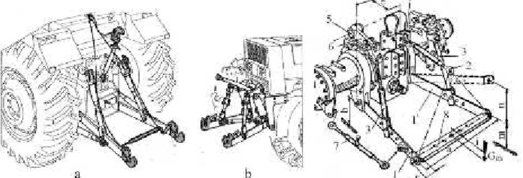
Coupling of the mounted agricultural machines to tractor is made by the intermediary of the suspension mechanism which is a three-point hitch system connected to tractor body, ensuring both machines coupling to the tractor and their positioning [22] in relation to the tractor and the ground surface. The suspension mechanism provides the possibility of lifting the agricultural machines from working position to transport position and vice versa.
mechanisms: one placed in the back and the other located in front of the tractor (the front suspension mechanism, Fig. 10b).
Suspension mechanism basic components are presented in Figure 24 c. Suspension mechanisms serve for coupling the semi-mounted machines to the tractor, in which case the connection between the tractor and the semi-mounted machine is achieved only by the lower coupling bars 1 and 1 ', in points F and G or by means of a cross tow bar 8, attached to the ball joints of the lower coupling bars 1 and 1’
Fig. 10. General construction of three-point hitch suspension mechanisms:
a – placed in the back of the tractor; b – placed in the front of the tractor; c- components [13]
Depending on the maximum traction power of tractors, the suspension mechanisms are divided into four constructive and functional categories (Table 1), each category having certain characteristic constructive sizes of the components established by national and international norms and regulations, in accordance with international standards SR ISO 730-1 + C1 / 2000.
Table 1. Suspension mechanism constructive categories[13]
Constructive category
I-a N I-a II-a III-a IV-a IV-a H
Maximum power at tractor traction bar:[kW]
max. 35
max. 48
max.
92 80…185 135…300 135…300
Three-point hitch suspension mechanisms provide three mobility degrees of the agricultural machine relative to the tractor body:
I – machine rotation in vertical-longitudinal plan, made around vertical instant centre of rotation CIRV, placed on the right Δ (fig. 11). This movement is achieved by changing the
position of the piston in the hydrostatic cylinder 4. If the hydraulic distributor also provides a floating position, due to this mobility degree the agricultural machine copies the microrelief of the field in the travel direction, independent of the tractor position. For this, the agricultural machine must be provided with support wheels, with metal rim or with tires;
II – machine rotation in horizontal plan, made around horizontal instant centre of rotation CIRH,placed on the right Δ’ (fig. 11). This movement is possible due to the fact that joints
A,B,C,G,E,Fat the ends of upper and lower coupling bars are spherical.
III – machine rotation in vertical- transversal plane, made around the longitudinal axis Δ "passing through CIRV and CIRH (fig. 11). This degree of mobility should be insured to trailed agricultural machinery with large working width (sowing machines, cultivators, etc.), for tracking by the machine of the micro-relief in vertically-transversal field, independent of the tractor. For this, at least one of the vertical rods must be able to free extension. Depending on the design adopted for the vertical rods, this degree of mobility can be achieved in two ways:
- connection between vertical rods and inferior coupling bars (articulations 1 and 1 ') is made by inserting the connecting pin in the extended hole of the connecting rod vertically elongate (fig. 11, hole B);
- vertical rods are telescopic, rods free elongation being possible in case of the bolt assembling the two parts of the tod is introduced in elongated hole (fig. 11C);
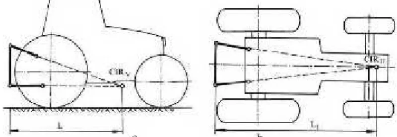
In case of the suspension mechanism which represents a spatial one and presents interest instantaneous rotation centre of the machine coupling device of the in a vertical plane (fig. 12a) and in horizontal plane (fig. 12b). In vertical plane, position of instantaneous rotation centre CIRV is at the intersection of extension directions upper and
the lower connected rods (fig. 12a) and in horizontally plane the centre position of CIRHis
at intersection extension directions of connected rod (fig. 12b). As through these points pass forces resultants which act to machine in the two planes, by CIRVand CIRH are
defined functional and dynamic suspension mechanism.
Fig. 12. – Graphical representation of instantaneous rotations centres positions of the tractor suspension mechanism: a - in horizontal plane (CIR
H); b - in vertical-longitudinal plane (CIRV) [13]
In work [14] authors present the experimental tests regarding to dynamic and energetic of the studied mono-axle tractor– semitrailer. In the first part are described studied aggregate components type and placement of the transducers on system components and mode of purchasing and storage data.In the second part of the work are presented the obtained results after tests on the base of which were elaborated conclusions regarding to the formation and exploitation optimization of singleaxle tractor -trailer systems: in case of the aggregate single-axle tractor unit is obtained a charging source of energy up to 70-80% of maximum payload of 1000 kg and heavier working conditions (field, land with a slope greater, higher speeds, etc). In case of semi-trailers used for payloads up to 1000 kg, to increase the engine tangential force (by adherence), it is necessary to carry out a load transfer from the trailer axle weight of tractor engines. The size of the load transfer depends on the position of the relative mass centre to the driven axle unit. Axle load value assigned to single-axle tractor, if it is not in the differential is limited by the maximum ergonomic operator effort at the handlebar grips driving during cornering, which is 18 daN.
coupling Fz and moment on the x, Cx direction, moment on the y, Cydirection, moment on the z, Cz=0 direction (z axis is the axis of connecting coupling of type cylindrical joint type).
For experimental tests, the components of the unit consist of single-axle tractor and trailer to a series of sensors placed in the diagram in figure 13. Space measuring actual speed travelled and work using a measuring device with additional wheel (TS, V).
In order to measure the above mentioned parameters were coupled the captors made (single-axle tractor wheels to the torque and the vertical and horizontal forces on the semi-trailer drawbar, etc.) with the strain gauge bridges with six N-channel 2302 (figure 13). The connections were made with cables of Hottinger type each 6.5 meters long (special tensometers) that were driven to the mobile laboratory arranged in a jeep. The mobile laboratory were seated two bridge strain gauge with a rechargeable power supplies 12 V and 150 Ah [1], [2], [3], [4].
Fig. 13 - Scheme of transducers located on aggregate and their connection to the decks, interface and computer [15]
Fig. 14 - Location of the captor efforts to measure forces and moments in connecting coupling [15]
Trials were made without payload and payload of 600 kg, uniformly distributed in the semi-bucket in the three-speed I, II and III in the following way: concrete road slope = 0, road = 0, stubble cereals meadow=0, causeway = 4,5, natural grassland = 7,5. On the paved road and meadow, in addition to travel in a straight line in stages I, II and III, were carried to the left or right turns at different speeds.
On the paved road and stubble cereal meadow were performed up trails of travel in a straight line, one sample for each gear, with load and no payload and by 4 samples turn left and right steps I and II without and payload. In terms of land road 6 samples were made travel in a straight line in stages I, II and III with load and no payload.
On causeway were performed 3 tests in a straight line without payload, 2 climbing samples payload speeds I and II.
In terms of natural grassland were performed two samples of went downhill speeds without payload in I and II. Looking at the results is clear that: wheel spin engines has minimum to transport empty (payload Q = 0) for moving the concrete road or maximum values when driving with Q = 600 kg stubble, respectively natural grassland located on a slope Q = 0. Also wheel spin forward speed increases with the values obtained during the tests being within the allowable limits of various test conditions.
The large number of samples, taken from different working conditions, allowed the experimental determination of the following quantities: normal tasks on the tractor wheels; side reactions at the tractor wheels; the driving force Fm; thrust of the couple, Fx; lateral coupling force, Fy; vertical coupling force, Fz; moment in the forward direction Cx and moment on the direction perpendicular to the moving direction, Cy. Based on data obtained during the tests it was determined analytical components of power balance and rolling resistance coefficient, which was determined as a global coefficient for both tractor and semi-trailer. Analyzing the data in the table shows the following: check the power balance of single-axle semitrailer tractor unit, resulting from theoretical research; with effective power increase with increasing speed and payload and varies depending on transport; the maximum values of the effective power were obtained analogously to the transport stubble cereals, on level ground and with the same payload travel on the road slope, the effective power at the same load, increases the slope of the road due to an increase in power consumption overcoming slope; overall rolling resistance coefficient has values greater than that given in the literature for the wheels of the same size and different types of road.
Kinematic analysis of spherical coupling as coupling element between tractor and trailer was studied in [16], the coupling between the tractor and trailer must meet the requirements of the EU. These conditions are: horizontal rotation, and rotation on a longitudinal plane of rotation on a transverse plane. Coupling mechanism that meets these conditions is cinematic ball head (the spherical joint).
Kinematic study of the spherical coupling
Figure 15 shows the ball coupling with three degrees of mobility in which (1) represents the item jointly with means of transport (tractor, agri-motor, car) and (2) is the element connected to the towing middle (trailer or equipment that assimilates with trailer). Element (1) binds to fix Ox0y0z0,mark and the element (2) binds to cell Oxyz mark denoted respectively Toand T.
Fig. 15 - Spherical coupling and specific kinematic elements [16]
At one point, it is consider that the landmark T Mobile execute a rotational motion generated against the benchmark T0, considered fixed at the time thought expressed by velocity components angular ωx, ωy, ωz relative to benchmark mobile T and
0 0
0 y z
x , ,
in
relation to the benchmark fixed T0. In reality the rotation occurs in the form of general movements as: singular movements ωx, ωy, ωzor
0 0
0 y z
x , ,
; combinations of movements, ωxωy,ωxωz, ωyωz,or
0 0 y
x
, x0z0, y0z0.
In general, T position in relation to T0 cell is defined by nine angles:
0 0 0 0 0 0 0 0
0 xy xz yx yy yz zx zy zz
xx ; ; ; ; ; ; ; ;
. Since T is triortogonal
ij ik jk
and
ij ik jk0
, it follows that among this nine angles there are dependent relations.resulting rotations with fix axis or simultaneously combined in pairs
,,
orsimultaneously the three movements
.Degrees of mobility allowed by the couple, who are recognized by the angular velocity components relative to the benchmark T mobile and fixed relative to the benchmark, are expressed by the following relationship [16]:
; cos ; sin cos sin ; cos sin sin z y x (1) ; cos ; cos sin sin ; sin sin cos z y x 0 0 0 (2)
where: - the angular velocity of the movement of precession ωp;
- angular velocity of movement of nutation ωn ;
- angular velocity of the own rotation ωr ;
From relations (1) and (2) results vector expression of angular velocity relative to mobile benchmark and fixed benchmark as follows:
k j
i y z
x
(3)
0 0
0 0 0
0i y j z k
x
(4)
k n
k
0 (5)
From relation (14) through derivation results angular acceleration:
n p r n r
px x x
k n
k
1 (6)
Kinematic study of the spherical coupling with three degrees of mobility (ωx, ωy, ωz) is required to demonstrate the dynamic interaction study in mechanical coupling that connects the tractor-semitrailer.
The dynamic study of spherical coupling
The mechanical model of spherical coupling is presented in figure 16 which is subject to mathematical processing for determining mechanical and geometric aspects that occur in a coupling; it is aimed to determine the coupling reaction '
R and analytical
equations that describe the element movement (2) in relation to the element (1):
Fig.16 – Mechanical model of the spherical coupling [16]
To determine the reaction in the coupling is used the kinetic moment and impulse theorem or kinetostatic method and results:
c
c
' r x x m r x m F
R (7) or
R
F mˆ rc m ˆ
ˆ rc
(8)where:R'- reaction forces result;
m – low weight of the element (2), which is trailed;
c
r - position vector of the element mass centre (2) in relation to the origin of the
mark;
Analytical expression of the relationship (7, 8) is:
c c c x y x z y z x y x z y z x y x z y z z y x ' z ' y ' x z y x m m F F F R R R 0 0 0 0 0 0 0 0 0 (9)
To determine the analytical equations of element movement (2) relative to element (1) are used the kinetic moment theorem or kinetostatic method (d'Alembert's principle) and results the movement equations:
z y x z y z x y x z y x M J J J M J J J M J J J 1 2 3 3 1 2 2 3 1 (10)where J1,J2,J3are the main moments of inertia of the element (2), while Mx,My, Mz are the components of the resulting moment of given or active forces, including friction forces.
The dynamic study of the coupling in general is quite complicated and in this context will be a theoretical study on the mechanical condition that may occur in reality.
Reaction forces issue is presented in table 1 and were measured based on relations (9).
The conducted study on spherical coupling that connects the tractor-semitrailer reached the following conclusions:
• Spherical coupling allows three mobility degrees evidenced by rotations (ωx, ωy,ωz) • Kinematic study specifies the parameters defining spherical coupling movements as: ψ – precession angle; φ – angle of rotation of its own, θ – mutation angle, angular velocities ωx, ωy,ωz; angular accelerations εx, εy, εz. This study is necessary for the dynamic study of spherical coupling.
• Dynamic study of spherical coupling was performed to determine the reaction as connecting force in coupling R', relations (7, 8) and movement equations of connected body (trail) relative to the tractor (relation 10). With this purpose, were created a total of 20 variants of movements in coupling depending on the velocity and angular acceleration values,.
• In tables 1 and 2 are presented the reaction components R
Rx,Ry,Rz,
and couplingmovement equations which are second order differential equations.
• Relations in tables 1 and 2 are particularly helpful for designing a coupling between tractor and semitrailer and optimize aggregate runway. Also, the respective relations constitute the fundamental basis of analysis on coupling that should meet EU standards, as study basis on comfort to be assured for aggregate service personnel and safety of transported material.
By moving aggregate tractor - semitrailer on uneven roads in spherical coupling high intensity shocks occur which requires that before accepting their operation to be tested on special Hydro - Pulse type installations which create conditions similar to operating ones.
CONCLUSIONS
REFERENCES
[1]. Bodea C., 2008 – Theoretical and experimental studies on coupling between tractor and trailer,Doctoral thesis, Transilvania Brasov University;
[2].Năstăsoiu, S., ş. a., 1983 – Tractors, Bucharest, Didactical and Pedagogical Publishing House, Bucharest;
[3]. Stoica, C, 2001 - Studies and research on mechanical linkages between vehicles towed and untrailed,Doctoral Thesis, Transylvania University Brasov;
[4]. Bodea C., Cândea I., Popescu S., 2008 - The dynamic study of tractor trailer unit on different runways, INMATEH - III;
[5].Buzdugan Gh., 1980 –Material Resistance,Technical Publishing House, Bucharest; [6]. Catrinoiu I., 2000 - Studies and research on improving tractor-trailer braking system dynamics by making tractor with braking on all wheels, Doctoral thesis,Transilvania UniversityBrasov;
[7]. Bodea C., Demetrescu I., 2006 - Road safety aggregates tractor-trailer and farm equipment,Mecanizareaagriculturii Magazine, no.3;
[8]. Bodea C., Ciupercă R., Cândea I., 2006 - Studies and research on road safety aggregates tractor trailer /Studiişicercetăriprivindsiguranţacirculaţieirutiere a agregatelor tractor remorcă, ASAS Scientifical Session/SesiuneŞtiinţifică ASAS
[9]. Cândea I., Bodea C., Bria N., Andrei I., 2008 - Kinematic analysis of spherical coupling as coupling element between tractor and trailer,INMATEH-III;
[10]. Demetrescu I.,1979 - Research on dynamic braking wheeled tractors with trailers to transport aggregate. Doctoral thesis, Brasov University;
[11]. Cândea I., ş.a, 2001 şi 2003, 2008- Static-Mechanical-Dynamics, Transilvania Brasov Publishing House, Braşov;
[12]. Bodea C., Nedelcu Ancuţa, Ciupercă R, 2005 -Current stage in the construction of agricultural trailers with roasted suspension, Scientific Papers (INMATEH), vol.VII;
[13]. Ormenişan N., 2014 - Theoretical and experimental research on the influence of automatic adjustment mechanisms for suspension of tractors on the dynamics and energetics aggregates show, Doctoral thesis, Transylvania University Braşov;
[14].Mocanu V, Hermenean I., 2010 – Research on the dynamics and power of aggregate formed of single-axle tractor and semitrailer, INMATEH – Agricultural Engineering, vol. 32, nr. 3/2010, pg. 59-64;
[15]. Mocanu V, Popescu S, Sperchez F, Hermenean I, 2001 - Method and equipment for experimental investigation of the dynamics and energetics in single-axle tractor mowing and transport work, 8th Conference with international participation of autovehicle and Environment, Transilvania Brasov University, Transylvania University Braşov, vol. II, pg. 321-326.
![Fig. 7 - Aggregate downhill flat road [7, 8, 9, 10]](https://thumb-us.123doks.com/thumbv2/123dok_us/8070372.2137751/4.892.226.667.980.1102/fig-aggregate-downhill-flat-road.webp)
![Fig. 9 - Aggregate tractor-semitrailer travelling on uneven road [12]](https://thumb-us.123doks.com/thumbv2/123dok_us/8070372.2137751/5.892.318.575.725.872/fig-aggregate-tractor-semitrailer-travelling-uneven-road.webp)
![Fig. 13 - Scheme of transducers located on aggregate and their connection to the decks, interface and computer [15]](https://thumb-us.123doks.com/thumbv2/123dok_us/8070372.2137751/8.892.211.685.363.532/scheme-transducers-located-aggregate-connection-decks-interface-computer.webp)