212
STUDIES AND RESEARCHES ON DESIGNING AND CONSTRUCTING A
MECHANICAL MACHINE FOR MEAT TENDERIZATION WITH
PNEUMATIC ACTION AND POSSIBILITIES FOR AUTOMATION
AUREL SIMION, CRISTIAN VASILE, MIRCEA BĂDESCU
1Doctoral School of Mechanical Engineering, University of Craiova 2Faculty of Agriculture and Horticulture, University of Craiova 3Doctoral School of Mechanical Engineering, University of Craiova
Keywords: mechanical tenderization, automation, process controller
ABSTRACT
Within meat processing technology the tenderization operation is important in the rapid maturation technique. Among tenderization methods, the least studied, yet with full ecological, biological and economical advantages is the mechanical tenderization. In this paper is presented an experimental model of machine of our own conception for the optimization of the tenderization process of the meat used for preparing traditionally products. Beside this the present paper presents the adequate system of pneumatic action and the automation elements of the working parameters which were made as our own conception for construction a machine for meat tenderization. Within the elaborated pneumatic scheme of driving there are identified the elements that can be electrically driven and the basis established scheme includes the programmable controller of the process. This allows the presenting of the organization schemes for every phase within the working process of machine and, finally, the cyclic scheme of function in order to establish the specific solutions for different meat types.
INTRODUCTION
The tenderization is a sensorial feature of the meat of high importance for establishing its final taste. The main feature is to facilitate the cutting, crushing and mixing the muscles fibers of the product with direct repercussions on the cumulative senses on tasting the final product. That's why the mechanical tenderization method can produce scraps after mastication that is smaller than biochemical methods and ensures against them superior eco-biologic qualities of the final product at low cost. [2,3]
Beating the meat method proposed by us to study will alow us to adjust different variations for working conditions of the machine in order to ensure optimum functional parameters for the main types of meat used. For this purpose the whole process is monitored in the framework of the pneumatic actuator of the designed machine by a microcontroller with programming posibilities after a previously established cyclogram. [9, 10]
MATHERIAL AND METHOD
213
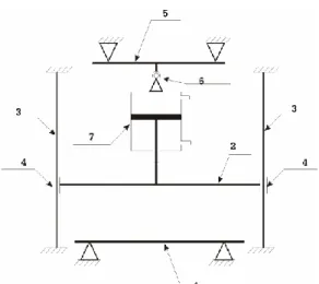
Fig. 2.1 The kinematical scheme of the machine Legend:
1. Placement plate 2. Mobile pressing plate.
3. Guiding colons – jointed with the placement plate.
4. Sliding bearings; they are jointed with the mobile plate for pressing and they glide on the guiding colons.
5. Upper securing cross part – it is jointed with the guiding colons. 6. Coupling ball – for correcting eventual coaxial deviations. 7. Driving pneumatic cylinder.
2.2. The pneumatic installation for action. The operating scheme of the installation [5, 10]
The machine is driven by mean of a pneumatic cylinder. In order to adjust the working parameters in a wide range and to achieve the automation goal of machine there was adopted a pneumatic scheme of operating which is presented in the schetch bellow:
The functioning of the pneumatic installation is characterized by three states: Release state – distributor (1) position R.
Operating – piston pushing – distributor (1), position I Operating withdrawal of piston – distributor (1), position T.
In function of the distributor state (2) there are possible two working ways: Fig. 2.2 Pneumatic operating scheme Legend:
1. Air pressuring unit – compressor.
2. Distributor with electrical command 5 HP/3 positions – it determines the working status (direction).
3. Distributor with electrical command 5 HP/2 positions – it determines the working way.
4. One-way switch of flow – drosel. 5. Anti – back flap.
214
With operation – controlled piston pushing (adjusting the speed at pressing) – distributor (2) not operating.
No control at piston pushing (maximal speed) – distributor (2) operating. With the controlled speed working way the functioning is as follows: Distributor (3) not in action
Distributor (1) is brought in position I
The air from the preparing unit follows the way branch B – branch B1 – flow flap – branch B2 – pneumatic cylinder. The air from cylinder will be evacuated on A way into the atmosphere. Due to flow flap (4), the speed of the piston will be determined by the flap adjustment. It is important that on the B3 way will not circulate air due to anti back flap (5).
In order to withdraw the piston, the distributor (2) is brought to T position where the air circulation will be: preparing unit – A branch – head of the piston. The evacuation of the air will be made as follows: piston – B2 branch – flow flap – B1 branch – B branch – atmosphere. In this case, the flow flap will have no effect because of the direction sense of the air circulation. As for the previous case, on the B3 branch there will not be air circulation due to anti back flap.
For the working way with maximal speed, the functioning will be as follows: Distributor (3) in action
Distributor (2) brought in I position
The air from the preparing unit follows the following path: branch B3 – flap (5) – branch B2 – pneumatic cylinder. The air from the cylinder will be evacuated on the A path into the atmosphere.
For piston withdrawal, the distributor (2) is brought in position T, where the air circulation will be: preparing unit – A branch – head of the piston. The evacuation of the air will be made through the following path: piston – branch B2 – flow flap – branch B1 – branch B – atmosphere. In this case the flow flap will have no effect due to the direction sense of the air circulation. On the B3 branch will be no air circulation due to anti back flap.
2.3. The electrical installation for operation and automation elements [6, 10] The achievement of the operating and automation electrical scheme there are needed the operation conditions for each state of machine as described upward. In parallel, the operating must comply with the technological conditions of the process. Besides that the operating should follow the requirements imposed by the functioning parameters.
The operating conditions are determined by a series of factors as follows: Machine architecture
Technological parameters
Flexibility in changing the value of the functioning parameters Ensuring operation protection
Ensuring the functioning within the limits of the working parameters.
2.3.1. The block operating scheme
From the pneumatic operation scheme results the elements that can be electrically driven:
Distributor of machine states (sense of direction) – this has two driving coils by which the distributor is brought to one of three states: R, I and T (see upward).
Distributor of the working way – by which there will be established the way the piston will be driven, the controlled speed or the maximal speed.
215
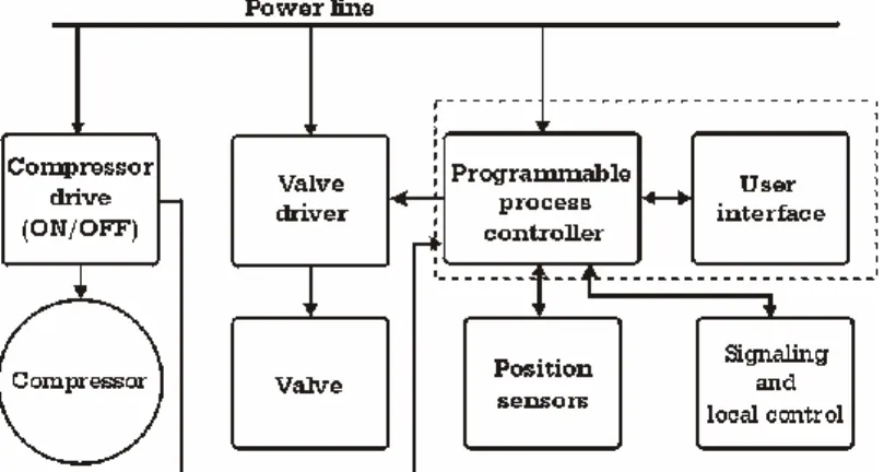
Fig. 3.1 The block operating scheme Legend:
Power line – electricity supply line
Compressor drive – on/off switch of the compressor Valve drive – air valve operating block
Position sensors – position sensors and state; they are: Superior course cut-off
UP position of mobile plate transmitter DOWN position of mobile plate transmitter
Cut – off protection flap – the machine is endowed with a flap that limits the working space of the machine in order to ensure operator protection
Sensor of compressor state – it signals the state of the compressor ON/OFF Programmable process controller, User interface.
Signaling and local control – through these features the operator can make functioning commands; they are:
Signaling of UP movement of the mobile plate Signaling of DOWN movement of the mobile plate Signaling the working way – manual/automatic
Signaling the driving mode – normal speed/maximal speed Command of DOWN movement of the mobile plate
Command of UP movement of the mobile plate Command START automatic cycle
Command STOP automatic cycle
2.3.2. Elements of automation and possibilities to use
The block scheme of electrical operation is endowed with the programmable controller of the process that is the main element of machine commands [6].
Programmable process controller is a real time programmable module with 8 digital entries and 8 digital exits. The implemented program into the controller has to
216
Fig. 3.2 The programmable controller
In the upper part there are 8 entries, from I1-I8. Also, here is mounted the power switch U+, U-. The exits O1-O8 are located in the bottom part. The connections to the controller are made by coupling the signal cables with the screw connectors according with the signal.
The interface with the user is made of an alphanumeric screen of LCD type which has 2 rows and 16 characters on each row. Also, there is a small bulb signaling that the processor is ON. The user can change the parameters by operating one of three buttons: M- menu; + plus – increase a value; - minus – decrease a value.
Elements of controller software
The implemented program in the controller implies the approaching of some aspects related to the state of the machine, the working way and the working parameters. The controller having as signals of entry the position sensors, the state of the compressor starting connector, the state of the protection flap and the state of the switchers of working way and driving mode can operate separately each state of machine.
The states of the machine are given by the working way and the position of the mobile plate.
With manual mode, the state of the machine is not limited by the program but for the lifting of the mobile plate so that the pneumatic cylinder of driving to not reach at the end of the course.
217
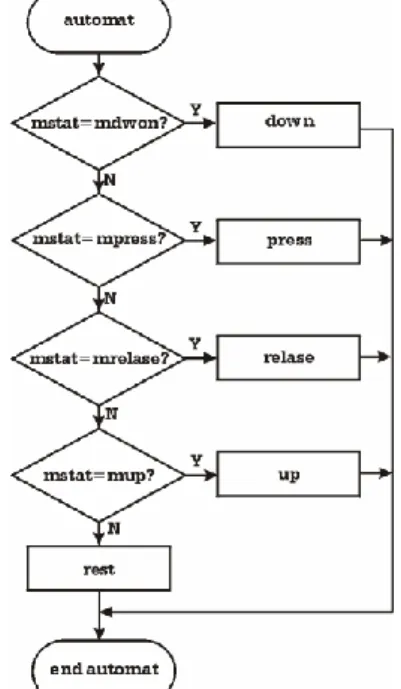
The two active machine working ways, automatic and manual can be graphically represented. With the same aspect there can be represented each of the working states of machine: the working graph of the repose state, of the pressing state, of the release state, etc. For instance, for the automatic working way, the graph of the function is presented below:
In this working mode there are tested the states and for every one there is executed the specific function. The states noted in the figure with their correspondents are:
mrest – repose
mdown – Down movement mpress – Pressing
mrelase – Release mup – Up movement
If the system variable is not something that implies movement (mdown, mpress, mrelase or mup) there results that it is in mrest – repose.
The cyclograma of functioning
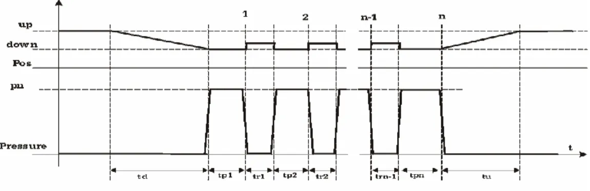
In the automatic working mode the variations of the mobile plate and of the pressure on the product are presented in the figure below:
Fig. 3.4 The cyclograma of functioning Where:
Up- the upper position of the mobile plate
Down – the position of the mobile plate when pressing Pn – nominal pressure on the product
Td – time of descending of the mobile plate Tp – pressing time
Tr – releasing time
Tu – time of upper movement of the mobile plate 1,2…n – number of performed subcycles
RESULTS AND DISCUSSIONS
The determination of the technological parameters of machine has had as main criterion the ensuring of quality of meat processing (tenderization) and means to optimize the working process by different working variants for specific meat types.
The pressing force – the product processing degree and the quality of tenderization are influenced by the pressing force. It is given by the features of the pneumatic cylinder and by the air pressure for its driving.
Fr S P
Fp c p (3.1)
Where:
218
Pc – the pressure from the cylinder
Sp – the surface of piston from pneumatic cylinder Fr – the friction force to guidance parts.
The impact force
When the mobile plate touches the product, the driving force of cylinder increases very much and an impact force occurs upon the product. Taking account the fact that this machine is still in researching, the influence of this force on the product was considered.
The impact force is given by the pressure from the cylinder and by the weight of the aggregate formed of mobile plate and pressing element. The determination of the impact force was made by measuring the impact speed, the calculus of the transferred energy to the product and the distance the product is pressed.
) ( 2 2 2 2 Gp Gi v m Gp Gi v m d Ep
Fi p p
p p (3.2) where:
Fi - the impact force
Ep – the energy of the pressing plate d – the distance of pressing
mp- the mass of the pressing plate plus the mass of the pressing element vp – the speed of the pressing plate at impact moment
Gi – the initial thickness of the product Gp – the thickness of the pressed product
Constructive parameters
There are several important issues that have to be accounted:
The loading capacity. It refers to the quantity of meat that can be processed in a cycle.
The maximal course of the pressing plate. The maximal pressing force.
These elements determine the constructive parameters and, consequently, its dimensions. There was chosen a loading capacity of maximum 4 kg. On this basis there were calculated the dimensions of the pressing surface as 180 x 380 mm. By adding safety distances results an active surface of 200 x 400 mm. This parameter was used to calculate the minimal distance between the two guiding colons:
c W
Dmin max (3.3)
Where:
Dmin – the minimal distance between colons
Wmax – the maximal length of the pressing surface
Φc – the diameter of the guiding colon; it will be calculated lately. The chosen maximal course, of 200 mm is given by:
The product height
The additional distance where the operator can maneuver the product inside machine.
On the basis of this course, along with the features of the pneumatic piston there can be calculated the active height of the colons:
pm cp
ac C H H
H max (3.4)
219
Hac- the active height of the colons Cmax – the maximal course
Hcp – the height of the aggregate formed of pneumatic cylinder and its fixing system
Hpm – the thickness of the aggregate formed of mobile plate and pressing element The maximal pressing force, as previously shown, is given by the formula (3.1.). Along with the maximal course there can be determined the characteristics of the pneumatic cylinder. This way there can be calculated the diameter of the piston:
c pcp P F D max 2 (3.5) Where:
Dpcp – the diameter of the piston from the driving pneumatic piston Pc – the pressure from the cylinder
Fmax – the maximal pressing force
For a maximal pressing force of 3,000 N and a working pressure of 6 bar there results:
Kgf 305.9 3000
max N
F 2 6.12Kgf/cm 6 bar Pc mm cm
D 7,98 79,8
12 , 6 9 , 305
2
There was chosen a pneumatic cylinder with the diameter of the piston of 85 mm and the course of the piston of 200 mm.
Along with the fixing system the pneumatic cylinder has a height Hcp=450mm. If the aggregate formed of mobile plate and the pressing element has the dimension of Hpm=80mm, from the formula (3.4.) there results the active height of the colons as follows:
mm Hac 20045080730
These dimensional parameters are used to final sizing of machine.
CONCLUSIONS
The mechanical tenderization is a modern technological component of the process of meat manufacture. It allows the worker to modulate the working state of the machine on different optimal variants of applying the impact force, the pressing time and release of the product. It permits the worker to adjust the working parameters to the type of the meat; this issue makes this paper original;
The mechanical tenderization of meat by optimizing the economical, biological and economical conditions of the working process is the main objective of this paper which with the help of the experimental model of the machine presented in our own conception it can solve the problem of meat tenderization within the meat processing technology;
The authors have designed and constructed a pneumatic installation of operating the machine for mechanical tenderization where all working states of the process are automatic;
The programmable controller of the process has his own software program that ensures a programming variant after a cyclograma that was established by the operator;
The working graphs that are presented in the paper determine the recording of the functioning cyclograma that is needed for the performance of functioning.
220
The present paper opens directions for researching in automation of different steps of technologies for meat processing.
BIBLIOGRAPHY
1. Banu C., Alexe P., Vizireanu A., 2003- Procesarea industrială cărnii, Ediţia a II a , Editura Tehnologică Bucureşti, pag. 643.
2. Davis, K. A., D. L. Huffman, and J. C. Cordray, 1975 - Effect of mechanical tenderization, aging, and pressing on beef quality. Journal of Food Science. Volume 40, Pages: 1222-1224.
3. Jeremiah L. E., L. L. Gibson, and B. Cunningham, 1999 - The influence of mechanical tenderization on the palatability of certain bovine muscles. Food Research International. Volume 32, Pages: 585-591.
4. Loucks, L. J., et all., 1984 - Effect of mechanical tenderization and cooking treatments upon product attributes of pre-rigor and post-rigor beef roasts. Journal of Animal Science. Volume 58, Pages: 626-630.
5. Măcuţa S., 2003 - Elemente de mecanică fină şi servomecanisme. Editura Didactică şi Pedagogică Bucureşti.
6. Oprean A. şi al., 1983 - Acţionări şi automatizări hidraulice. Sisteme mecano-pneumo-electrohidraulice. Editura Tehnică Bucureşti.
7. Schilling M.W., N. G. Marriott, H. Wang, and M. B. Solomon, 2003 - Characteristics of USDA utility cow beef subjected to blade tenderization and hydrodynamic shock waves. Journal of Muscle Foods. Volume 14, Pages: 131-142.
8. Seideman, S. C., et all., 1977 - Blade tenderization of beef psoas major and semitendinosus muscle. Journal of Food Science. Volume 42, Pages: 1510–1512.
9. Simion A., Bădescu M., 2013 – Studii şi cercetări privind proiectarea şi realizarea unei maşini destinate tenderizării cărnii pentru obţinerea produselor tradiţionale. First International Conference, Danube – Black Sea, 3E-Energy, Environment&Efficiency, Universitatea Dunărea de Jos, Galaţi.