Networking Modes
TOBY-L2 series
Application Note
Abstract
This document describes the two operational modes of the TOBY-L2 module and how to provide connectivity to customer modems.
www.u-blox.com
UBX-14000479 - R03
Document Information
Title Networking Modes
Subtitle TOBY-L2 series
Document type Application Note Document number UBX-14000479
Revision and date R03 17-Jul-2015
Document status Early Production Information Document status explanation
Objective Specification Document contains target values. Revised and supplementary data will be published later.
Advance Information Document contains data based on early testing. Revised and supplementary data will be published later. Early Production Information Document contains data from product verification. Revised and supplementary data may be published later. Production Information Document contains the final product specification.
This document applies to the following products: Product name
TOBY-L2 series
u-blox reserves all rights to this document and the information contained herein. Products, names, logos and designs described herein may in whole or in part be subject to intellectual property rights. Reproduction, use, modification or disclosure to third parties of this document or any part thereof without the express permission of u-blox is strictly prohibited.
The information contained herein is provided “as is” and u-blox assumes no liability for the use of the information. No warranty, either express or implied, is given, including but not limited, with respect to the accuracy, correctness, reliability and fitness for a particular purpose of the information. This document may be revised by u-blox at any time. For most recent documents, please visit www.u-blox.com. Copyright © 2015, u-blox AG
UBX-14000479 - R03 Early Production Information Contents
Contents
Contents ... 3
1
Introduction ... 5
2
Bridge mode ... 6
2.1 General description ... 6
2.2 DTE connectivity ... 7
2.2.1 IPv4 ... 7
2.2.2 IPv6 ... 7
2.3 Connection Manager development guidelines ... 8
3
Router mode ... 11
3.1 General description ... 11
3.2 DTE connectivity ... 12
3.2.1 IPv4 ... 12
3.2.2 IPv6 ... 12
3.3 Conflicts between RNDIS private network and cellular network in router mode ... 13
3.4 How to set the port forwarding on the module in router mode ... 14
4
RNDIS throughput issue on a Linux system ... 15
5
Additional information ... 16
5.1 AT commands examples ... 16
5.1.1 Operational mode switch +UBMCONF ... 16
5.1.2 Target IP configuration +UIPCONF ... 16
5.1.3 IP configuration of the PDP contexts/EPS bearer +UIPADDR ... 17
5.1.4 IP tables configuration (router mode) +UIPTABLES ... 18
5.1.5 Static routes configuration (router mode) +UIPROUTE ... 19
5.1.6 USB interface profile configuration +UUSBCONF ... 20
5.2 Dial-up connection ... 23
5.2.1 Dial-up PPP configuration on Linux systems ... 25
5.2.2 Dial-up PPP configuration on Windows systems ... 26
5.3 Local dial-up connection ... 28
5.4 Multiple PDP contexts/EPS bearers ... 29
5.4.1 Module cellular connectivity in relation to the USB interface profile and networking mode ... 30
Appendix ... 31
A
IP subsystem configuration ... 31
A.1 IPv4 interface configuration in Windows OS ... 31
A.2 IPv4 interface configuration in Linux OS ... 31
A.3 IPv6 interface configuration in Windows OS ... 32
UBX-14000479 - R03 Early Production Information Contents
B
Router/Bridge mode configuration in Linux ... 34
C
List of acronyms ... 35
Related documents ... 36
Revision history ... 36
UBX-14000479 - R03 Early Production Information Introduction
1
Introduction
TOBY-L2 is a multi Radio Access Technology (RAT) module capable of operating in 2G, 3G and 4G mobile networks. Regardless of the currently selected RAT, the packet switched connectivity over the USB virtual Ethernet interface may be established in two different networking modes:
Bridge mode: the IP termination of the data connectivity is on the customer’s application processor and the module acts as a bridge device (similar to a USB dongle).
Router mode: the IP termination is placed on the module itself. In this configuration the data connectivity of the customer’s application processor is provided through routing procedures. The module is operating as a mobile router.
This document describes the two operating modes and how the IP connectivity is provided. In addition, the document provides additional information regarding:
Development strategies for a reference Connection Manager useful in bridge mode. Description of the NAT (Network Address Translation) configuration useful in router mode. Description of the IPv6 configuration in bridge mode.
Dial-up IPv4 configuration.
How to increase the throughput on Linux OS.
For the sake of clarity, the u-blox cellular module is also referred to as the “target”, while the device connected to it is called the “DTE” (Data Terminal Equipment). The physical connection between the target and the DTE is established through the USB interface, which supports different logical interfaces (RNDIS, CDC-ECM and CDC-ACM).
The following symbols are used to highlight important information within the document:
An index finger points out key information pertaining to module integration and performance. A warning symbol indicates actions that could negatively impact or damage the module.
UBX-14000479 - R03 Early Production Information Bridge mode
2
Bridge mode
2.1
General description
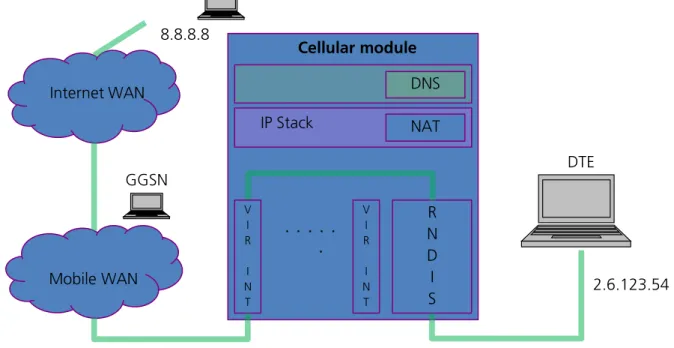
In bridge mode the target acts as a bridge device between the mobile network and the DTE: the IP termination of the data connection is placed on the DTE network subsystem. For each active PDP context or EPS bearer, the DTE assigns (i.e. “binds”) the IP address to its USB virtual Ethernet interface and configures its routing rules. Each IP address associated with an active PDP context/EPS bearer is granted to the target by the mobile network, and it shall be retrieved through appropriate AT commands.
NAT IP Stack
. . .
.
V I R I N T R N D I S DNS V I R I N T 2.6.123.54 Internet WAN 8.8.8.8 GGSN Mobile WAN DTE Cellular moduleFigure 1: Bridge mode, single PDP context
NAT IP Stack
. . .
.
V I R I N T R N D I S DNS V I R I N T 2.6.123.54 120.34.86.3 Mobile WAN Internet WAN 8.8.8.8 GGSN1 GGSN2 DTE Cellular moduleUBX-14000479 - R03 Early Production Information Bridge mode
Since several PDP context/EPS bearers can be activated, multiple IP addresses can be specified on the same physical interface by the use of interface aliases in Windows based systems and/or virtual interfaces in Linux based systems. The target is able to handle up to 8 different PDP contexts/EPS bearers.
2.2
DTE connectivity
This section explains how the DTE’s network interfaces shall be configured to obtain connectivity through an active PDP context/EPS bearer. The steps for the configuration of Windows and Linux based systems are described. Finally, guidelines for the implementation of a Connection Manager application are provided.
The description covers both IPv4 and IPv6 addressing. Appendix A provides additional information on the configuration commands used in Windows and Linux systems.
2.2.1
IPv4
In bridge mode, the configuration of the DTE’s network interfaces shall be performed manually because the automatic configuration through DHCP (Dynamic Host Configuration Protocol) server is not supported.
See u-blox AT commands manual [1] for a detailed AT commands description and AT commands examples Application Note [2] for more examples on IPv4 configuration.
Perform the following steps for the configuration of every active PDP context/EPS bearer:
1. The DTE must retrieve the associated IP address with +CGPADDR or +CGDCONT, or +CGCONTRDP AT commands.
2. The DTE must assign the retrieved IP address to its USB virtual Ethernet interface as an alias.
3. The DTE must retrieve the network assigned DNS server addresses with +CGCONTRDP AT command. 4. In case of multiple active primary PDP contexts (each with its own IP address), each application running on
the DTE should bind to a specific IP alias, to let the target forward the IP traffic to the desired PDP context. 5. The target creates a USB virtual Ethernet interface in order to reply to ARP requests. The configured IP
address has only local meaning. The DTE must retrieve this information with +UIPADDR AT command. 6. The DTE shall add a routing rule for its USB virtual Ethernet in order to ensure connectivity over the USB link.
The gateway IP address of this rule must be the IP address retrieved at previous step. See Appendix A.1 and Appendix A.2 for additional information.
2.2.2
IPv6
For a detailed description of link local and global address see appendix A.
The local connectivity is ensured by the automatic configuration of the link local address. The target’s link local address is automatically set and can be retrieved with +UIPCONF. The global connectivity is ensured by the global address, which should be univocal.
The global address consists of 128 bits, where the 64 bit long prefix is granted by the mobile network and the 64 bit long suffix is obtained from the less significant bits of the link local address.
In general terms, the global connectivity configuration of the network node shall be performed automatically by the IPv6 network through the use of DHCPv6 and/or IPv6 Neighbor Discovery Protocol (NDP), or manually by the user. Typically, the DCHPv6 is not supported on mobile networks; hence only two cases shall be analyzed. The IPv6 auto configuration with the NDP is performed within the handshake of Router Solicitation (RS) / Router Advertisement (RA) and Neighbor Solicitation (NS) / Neighbor Advertisement (NA) messages. All this messages are encapsulated into ICMPv6 packets.
The network node is broadcasting RS to locate routers on the connected link, while the routers are responding with the RA. The RA message provides the prefix of the announced network.
The network node is also broadcasting NS messages to determine the other nodes on the same physical link. These nodes shall be reached within link local addresses. The NS/NA handshake is equivalent to the IPv4 Address Resolution Protocol (ARP).
UBX-14000479 - R03 Early Production Information Bridge mode
If the mobile network supports the IPv6 auto-configuration then the following steps must be followed for each successful PDP context activation:
The Router Advertisement sent from the mobile network is forwarded to the USB virtual Ethernet interface of the DTE.
The DTE processes the RA message and configures its global address and its routing rules. If the procedure is correctly completed then the host is provided with a global IPv6 address and with the IPv6 address (global or local) of the next-hop router.
Optionally the RA message can provide DNS server addresses. If present then the DTE shall apply the DNS configuration, otherwise the DTE should perform manual configuration.
If the mobile network does not support NDP then the DTE must perform a manual configuration for the global IPv6 address, next-hop address and DNS address for each successful PDP context activation:
The prefix of the global address should be equal to the first 64 bits of the IP address retrieved with +CGPADDR AT command. The suffix should be equal to the last 64 bits of the USB virtual Ethernet interface link local address.
The IPv6 address of the DNS server should be set. The user can choose between the set of the world-wide known DNS servers and addresses provided by the command +CGCONTRDP.
The default route should be created toward a fake IPV6 address on the same network in order to forward the internet traffic on the USB link.
To prevent continuous transmission of Neighbor Solicitation messages to this fake address the DTE should add it to its IPv6 neighbor list.
2.3
Connection Manager development guidelines
The main tasks of the Connection Manager application running on the DTE are: Monitor the status of the PDP contexts/EPS bearers.
Set up the IP configuration of the virtual interface for the activated PDP contexts (IP, gateway, DNS, routing rules).
Unset the IP configuration of the virtual interface for the deactivated PDP contexts (IP, gateway, DNS, routing rules).
Three different implementation strategies for a Connection Manager are defined: “basic”, “smart” and “hybrid”.
Appendix A provides some examples of commands for setting IP address, gateway and DNS on Windows and Linux OS.
In bridge mode:
The +UIPADDR AT command retrieves the gateway IP of an active PDP context. The +CGDCONT AT command retrieves the PDP context IP.
The <cid> of a mobile terminated context/bearer is assigned according to the rules below:
o Primary context (2G/3G) or default bearer (4G): first <cid> not defined in the ordered list = [4, 3, 2,1, 8, 7, 6, 5]
o Secondary context (2G/3G) or dedicated bearer (4G): first <cid> not defined in the ordered list = [8, 7, 6, 5, 1, 2, 3, 4]
Some network operators on their data networks support a MTU (maximum transmission unit) smaller than the standard 1500 bytes. In such cases then the IP data flow will incur IP fragmentation, thus lowering the throughput performance. In a network requiring a lower MTU then the customer should change his operating system to apply the new value over the virtual USB Ethernet link.
UBX-14000479 - R03 Early Production Information Bridge mode
2.3.1.1 Basic implementation
The Connection Manager (CM) configures the DTE by taking into account the status of each PDP context/EPS bearer, retrieved with +CGDCONT and +CGACT AT commands.
The Connection Manager must properly set the IP, gateway and DNS addresses for the RNDIS and CDC-ECM interface aliases/virtual interfaces. Once the PDP context/EPS bearers are activated and the configuration is set, the Connection Manager must periodically poll the target to eventually update the settings or to track changes of the PDP contexts’ state, caused e.g. by the deactivation of PDP contexts commanded by the network due to roaming or temporary network’s issues.
The following list of instructions can be used as reference for the implementation on IPv4 based networks: In 2G/3G: define a PDP context with +CGDCONT AT command and activate it with +CGACT AT command.
In 4G: the default initial PDP context is automatically activated during attach and it can be defined with AT+UCGDFLT AT command.
Periodically poll the PDP contexts’ state (e.g. 5 s) with +CGACT read command (polling shall be maintained as long as the CM application is running).
When the PDP context is active, get the needed IP address with +CGPADDR, +CGCONTRDP and +UIPADDR AT commands.
Set up the OS with IP alias/virtual interfaces, routing rules and DNS configuration.
If the PDP context is deactivated (it can be inferred by the information text response to the +CGACT read command) then remove all the settings for the related interface alias/virtual interface.
In the case of IPv6 based context the following instructions can be performed:
If the mobile network supports NDP then set the DNS server if the DNS server is not present in the RA. In the case the network in not sending RA:
o Find out the prefix granted by the mobile network with the AT command +CGPADDR.
o Set the global IPv6 of the DTE: upper 64 bits of the network prefix plus the lower 64 bits of link local address of the context. Since the link local address of the context is associated with a virtual interface, its link local address is always equal to fe80::200:ff:fe00:0/64. The lower part of the link local address correspond to 200:ff:fe00:0.
o Set the DNS servers.
o To prevent continuous NS transmissions, set a route to a fake neighbor on the DTE and insert its address into the IPv6 neighbor list.
2.3.1.2 Smart implementation
This solution is event-driven: the Connection Manager application relies on URC notifications issued by the target at the AT interface to track the changes of the connectivity through the mobile network.
The following list of instructions can be used as reference:
In 2G/3G: define a PDP context with +CGDCONT and activate it with +CGACT AT commands.
In 4G: the default initial PDP context is automatically activated during attach. It can be defined with AT+UCGDFLT.
Enable the URC of +CGREG,+CEREG, and +CGEREP AT commands. Activate a PDP context with +CGACT AT command.
Based on the URC issued by the target, handle the IPv4 and/or IPv6 configurations on the DTE. The activation of a context should trigger the configuration of the related interface alias/virtual interface, while the deactivation of a context should remove the configuration of the related interface alias/virtual interface. 2.3.1.3 Hybrid implementation
This approach is a simultaneous combination of the previous two solutions:
Apply the “smart” approach by enabling and handling the URC related to registration and connectivity events.
UBX-14000479 - R03 Early Production Information Bridge mode
Apply the “basic” approach as a safety net with an appropriate polling timer (e.g. 20 s).
In this configuration the burden of the continuous polling mechanism is mitigated by the handling of the URC notifications. The polling mechanism with a larger timer offers a backup solution in case URC notifications are lost.
UBX-14000479 - R03 Early Production Information Router mode
3
Router mode
3.1
General description
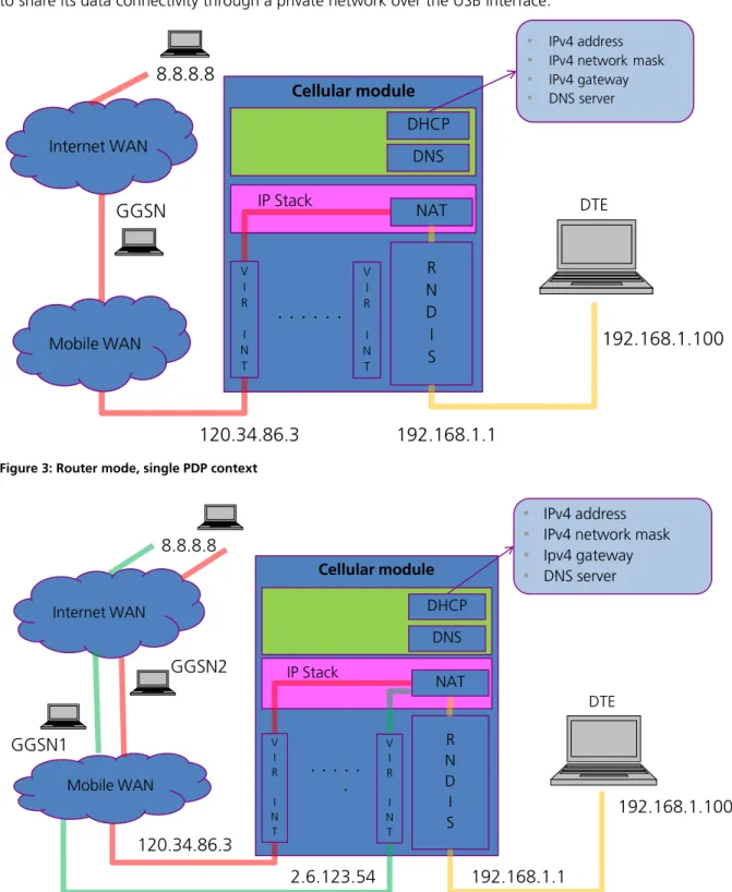
In the router mode, the IP termination is on the target: the module acts as a mobile network router and it is able to share its data connectivity through a private network over the USB interface.
NAT IP Stack
. . . .
R N D I S DHCP DNS Mobile WAN DTE V I R I N T V I R I N T192.168.1.100
192.168.1.1
120.34.86.3
• IPv4 address
• IPv4 network mask
• IPv4 gateway
• DNS server
Internet WAN
8.8.8.8
GGSN
Cellular module
Figure 3: Router mode, single PDP context
IP Stack
. . .
.
R N D I S DHCP DNS V I R I N T V I R I N T 192.168.1.100 192.168.1.1 120.34.86.3 2.6.123.54 DTE • IPv4 address • IPv4 network mask • Ipv4 gateway • DNS serverMobile WAN Internet WAN 8.8.8.8 GGSN1 GGSN2 NAT Cellular module
UBX-14000479 - R03 Early Production Information Router mode
3.2
DTE connectivity
This section provides information on how the DTE connectivity shall be configured in router mode. The description covers both IPv4 and IPv6 addressing. Appendix A provides additional information on the configuration commands used in Windows and Linux systems.
3.2.1
IPv4
In router mode the IP termination is placed on the target. For each PDP context/EPS bearer activation, the target creates an internal IP interface and assigns it the IP address of the activated PDP context/EPS bearer. The configuration of each internal IP interface can be retrieved with the +UIPADDR AT command.
Because the target is running a DHCP server on the USB link, the configuration of the DTE’s virtual Ethernet interface can be performed automatically using a DHCP client or manually by specifying a static IP address. The IP addresses of the virtual Ethernet interfaces of the target and of the DTE shall belong to the same private subnetwork to allow a two way communication.
The DTE is not aware of the target’s mobile connectivity state and should retrieve it with at the +CGACT? AT command or any other equivalent AT command.
The DTE connectivity is achieved by forwarding the traffic between the target’s USB virtual Ethernet interface and the internal IP interfaces. The IP traffic will be finally forwarded to an active PDP context/EPS bearer based on the target’s routing table.
For each internal IP interface, the target will create a routing rule: the PDP contexts are activated consequentially and the activation history is stored in the target. The default gateway is always associated with the PDP context/EPS bearer that was activated first. Once this context/bearer is deactivated, the default gateway is re-associated with the next active PDP context/EPS bearer reported in the activation history.
The AT command +UIPROUTE shall be used to define static routes towards a specific PDP context/EPS bearer. The static routes may be set for a specific host IP or a specific network segment (subnetwork). The configuration of the static routes is volatile and it is lost at the target reboot.
The +UIPCONF, +UIPTABLES, +UIPROUTE and +UIPADDR AT commands configure the NAT, in this case port forwarding and IP masquerading), firewall, routing and of the USB virtual Ethernet interface.
Section 5.1 provides some reference examples.
3.2.2
IPv6
UBX-14000479 - R03 Early Production Information Router mode
3.3
Conflicts between RNDIS private network and cellular network in
router mode
Since several mobile providers use private network addressing, the cellular network may be in conflict with the private network associated with the USB virtual Ethernet interface. This may lead to an incorrect routing configuration.
To avoid loss of connectivity, the module should be properly configured:
Command Response Description
AT+UIPCONF? +UIPCONF: "10.18.130.1","255.255
.255.0","10.18.130.100","10.18.1 30.254","FE80::2C60:20FF:FE56:2A 2D/64"
OK
Retrieve the network configuration on the module USB virtual Ethernet interface.
AT+UIPADDR= +UIPADDR: 1,"CCINET0","5.168.120
.242","255.255.255.255","","" +UIPADDR: 2,"CCINET1","46.12.30. 162","255.255.255.255","","" +UIPADDR: 4,"CCINET3","10.18.130 .248","255.255.255.255","","" OK
Retieve the network configuration on the PDP context/EPS bearer.
AT+UIPCONF="192.168.254.1","255. 255.255.0","192.168.254.100","19 2.168.254.100"
OK If conflicts are present, the IP network configuration of the USB virtual Ethernet interface shall be adjusted to provide a new IP address/mask and a new range for the DHCP server running on the USB virtual Ethernet interface.
AT+CFUN=1,1 OK Finally, the module should be rebooted to
make effective the applied changes.
It is worth noticing that also the host IP network configuration shall be verified and when needed adjusted (especially in the case of static addressing).
UBX-14000479 - R03 Early Production Information Router mode
3.4
How to set the port forwarding on the module in router mode
To ensure that the DTE is reachable from the outside public network, port forwarding features shall be properly configured. For a proper configuration through +UIPTABLES command, the following information shall be retrieved:
the IP address of the host <host_IP>
the port number on which the host is offering the service to the external network <host_port>
the port number on which the target is listening <target_port>
the protocol type used by the connection (e.g. 6 – UDP protocol, 17 – TCP protocol) <prot_num>
In the following table some examples are provided:
Example ID AT command Explanation
1 AT+UIPTABLES="-t nat -A PREROUTING -p <prot_num> --dport <target_port> -i ccinet+ -j DNAT --to <host_IP>:<host_port>"
Set port forwarding rules on all the PDP contexts/EPS bearers.
2 AT+UIPTABLES="-t nat -D PREROUTING -p <prot_num> --dport <target_port> -i ccinet+ -j DNAT --to <host_IP>:<host_port>"
Unset port forwarding rules on all the PDP contexts/EPS bearers.
3 AT+UIPTABLES="-t nat -A PREROUTING -p <prot_num> --dport < target_port> -i ccinet<CID-1> -j DNAT --to <host_IP>:<host_port>"
Set port forwarding rule on the PDP context/EPS bearer number CID. <CID-1>
means CID number minus 1. 4 AT+UIPTABLES="-t nat -A PREROUTING -p prot_num>
--dport < target_port> -i ccinet<CID-1> -j DNAT --to <host_IP>:<host_port>"
Unset port forwarding rule on the PDP context/EPS bearer number CID. <CID-1>
means CID number minus 1.
UBX-14000479 - R03 Early Production Information RNDIS throughput issue on a Linux system
4
RNDIS throughput issue on a Linux system
On a Linux system, to reach the maximum throughput it is necessary to recompile the kernel. Apply the following modification in /kernel/drivers/net/usb/usbnet.c:
Replace “size_t size = dev->rx_urb_size;“ with “size_t size = (16*1024);” If it is not possible to recompile the kernel, then try to use CDC-ECM.
As last resort try to use the following command:
AT+UDCONF=67,0
UBX-14000479 - R03 Early Production Information Additional information
5
Additional information
This section focuses on useful features which are common for both networking modes. Examples are provided in the next subsections.
For a complete description of the AT commands see the u-blox AT Commands Manual [1].
5.1
AT commands examples
This section will provide some examples on how to configure the network connectivity on the target through the AT commands. Some AT commands can be used in both networking modes (i.e. +UBMCONF, +UIPCONF, +UIPADDR), while other AT commands are specific of each networking mode (i.e. +UIPTABLES).
5.1.1
Operational mode switch +UBMCONF
The networking mode can be set through the +UBMCONF command. The AT command +UBMCONF can also be used to identify the IP networking mode in which the target is operating.
The new setting will be effective after the module reboot.
Command Response Description
AT+UBMCONF=1 OK Set the router networking mode. This is the default
and factory-programmed value.
AT+UBMCONF=2 OK Set the bridge networking mode.
AT+UBMCONF? +UBMCONF:2
OK
Get the networking mode. In the example the target is operating in bridge mode.
5.1.2
Target IP configuration +UIPCONF
The USB virtual Ethernet interface of the target is provided with a private IPv4 address and a link local IPv6 address. The IP addressing on the target can be configured through the +UIPCONF AT command in both networking modes:
In router mode, the +UIPCONF command can configure or retrieve the private IPv4 address, the link local IPv6 address of the RNDIS interface and the range of the addresses provided by the DHCP server.
In bridge mode, the +UIPCONF command can configure or retrieve the private IPv4 address of the USB virtual Ethernet interface (mainly for debugging purposes).
Command Response Description
AT+UIPCONF="192.168.2.1","255 .255.255.0","192.168.2.100"," 192.168.2.100"
OK In router mode: set the target IP address to “192.168.2.1”, the mask of the private network to “255.255.255.0”, the first IP address of the DHCP range to “192.168.2.100”, and the last IP address of the DHCP range to “192.168.2.100”. Currently the platform allows only one client on the USB virtual Ethernet interface.
In bridge mode: set the target IP address to “192.168.2.1” and the mask of the private network to “255.255.255.0”. Other parameters are ignored.
UBX-14000479 - R03 Early Production Information Additional information
Command Response Description
AT+UIPCONF? +UIPCONF: "192.168.5.1","255.
255.255.252","192.168.5.2","1 92.168.5.2","FE80::2C60:20FF: FE56:2A2D/64"
OK
In router mode: get the target IP address “192.168.5.1”, the mask of the private network “255.255.255.252”, the first IP address of the DHCP range “192.168.5.2”, and the last IP of the DHCP range “192.168.5.2”. Due to the selected netmask, the range is limited to only one guest. The link local IPv6 address “FE80::2C60:20FF:FE56:2A2D/64” is finally reported
In bridge mode: get the target IP address “192.168.5.1”, and the mask of the private network “255.255.255.252”. Router-mode specific parameters (e.g. DHCP range), if previously configured, are also displayed but should be discarded.
5.1.3
IP configuration of the PDP contexts/EPS bearer +UIPADDR
The +UIPADDR command provides IP addresses of the interfaces for the mobile network connectivity. However, it is not able to provide information on an interface operating in bridge mode which has been configured by the mobile network only with an IPv6 address and without the IPv4 address.
The context ID is the same contained in the information text response of the +CGACT and +CGDCONT read commands.
Command Response Description
AT+UIPADDR= +UIPADDR:
1,"USB0:0","5.168.120.242","2 55.255.255.255","",""
4,"USB0:3","76.18.130.262","2 55.255.255.255","",""
OK
In bridge mode: get the list of the active PDP contexts/EPS bearers and associated IP addresses. Two contexts are active. The first context has ID 1 and is associated with the virtual interface USB0:0. Its IP address is 5.168.120.242. The second context has ID 4 and is associated with the virtual interface USB0:3. Its IP address is 76.18.130.262.
AT+UIPADDR= +UIPADDR:
1,"CCINET0","5.168.120.242"," 255.255.255.255","","" 2,"CCINET1","46.12.30.162","2 55.255.255.255","","" 4,"CCINET3","76.18.130.262"," 255.255.255.255","","" OK
In router mode: get the list of the active PDP contexts/EPS bearers. Three contexts are active. The first context has ID 1 and is associated with the interface CCINET0. Its IP address is 5.168.120.242. The second context has ID 2 and it is associated with the interface CCINET1. Its IP address is 46.12.30.162. The third context has ID 4 and it is associated with the interface CCINET3. Its IP address is 76.18.130.262.
AT+UIPADDR=4 +UIPADDR:
4,"USB0:3","76.18.130.262","2 55.255.255.255","",""
OK
In bridge mode: get the configuration of the active PDP context/EPS bearer with ID 4. This context is associated with the virtual interface USB0:3 and its IP address is 76.18.130.262.
AT+UIPADDR=2 +UIPADDR:
2,"CCINET1","46.12.30.162","2 55.255.255.255","",""
OK
In router mode: get the configuration of the active PDP context/EPS bearer with ID 2. This context is associated with the interface CCINET1 and its IP address is 46.12.30.162.
AT+UIPADDR=3 ERROR In router mode the context with ID 3 is not
active; in bridge mode either the context with ID 3 is not active or it is active but IPv4 address has not been assigned to it.
AT+UIPADDR=2 +UIPADDR:
2,"CCINET1","","","2001::2:20 0:FF:FE00:0","FE80::200:FF:FE 00:0"
OK
In router mode: get the configuration of the active PDP context/EPS bearer with ID 2. This context is associated with the virtual interface CCINT1 and its global IPv6 address is 2001::2:200:FF:FE00:0, while the local one is FE80::200:FF:FE00:0.
UBX-14000479 - R03 Early Production Information Additional information
Command Response Description
AT+UIPADDR=2 +UIPADDR:
2,"CCINET1","46.12.30.162","2 55.0.0.0","",""
OK
In router mode: get the configuration of the active PDP context/EPS bearer with ID 2. This context is associated with the interface CCINET1 and its IP address is 46.12.30.162.
5.1.4
IP tables configuration (router mode) +UIPTABLES
The +UIPTABLES command can be used to modify the firewall and port forwarding configuration of the target. All the rules are immediately applied and are also stored in the NVM (Not Volatile Memory). In case they shall be edited, it is recommended to delete the previously saved configuration with AT+UIPTABLES=.
Command Response Description
AT+UIPTABLES="-L –t nat" Chain PREROUTING (policy ACCEPT)
target prot opt source destination
Chain OUTPUT (policy ACCEPT)
target prot opt source destination
Chain POSTROUTING (policy ACCEPT)
target prot opt source destination
MASQUERADE 0 -- anywhere anywhere
MASQUERADE 0 -- anywhere anywhere
MASQUERADE 0 -- anywhere anywhere
MASQUERADE 0 -- anywhere anywhere
MASQUERADE 0 -- anywhere anywhere
MASQUERADE 0 -- anywhere anywhere
MASQUERADE 0 -- anywhere anywhere
MASQUERADE 0 -- anywhere anywhere
OK
Get the rules of the nat table.
The default table is filtered, hence the command “-L” is equivalent to “-L –t filter”
AT+UIPTABLES="A PREROUTING -t na-t -i ccine-t3 -p -tcp --dport 80 -j DNAT --to 192.168.1.100:22"
AT+UIPTABLES="-A INPUT -p tcp -m state --state NEW --dport 80 -i ccinet3 -j ACCEPT"
OK Both rules are required to set the port forwarding. The TCP traffic arriving on the port 80 of the interface ccinet3 is forwarded to the port 22 of the IP 192.168.1.200.
AT+UIPTABLES="-A INPUT -p tcp --destination-port 80 -j DROP"
OK Set the blocking rule on the TCP traffic arriving on the port 80.
AT+UIPTABLES="-D INPUT 6" OK Delete the 6-th rules of the chain INPUT.
AT+UIPTABLES=" -A OUTPUT -p icmp --icmp-type 8 -j DROP"
OK Block ICMP echo-request.
UBX-14000479 - R03 Early Production Information Additional information
5.1.5
Static routes configuration (router mode) +UIPROUTE
The +UIPROUTE command can be used to create/modify the static routes of the target. All the rules are immediately applied and are not stored in the NVM. If they need to be edited, it is recommended to delete the previous configuration. The +UIPROUTE command may overwrite the default routing rule or may lead to the loss of connectivity.
Command Response Description
AT+UIPROUTE? +UIPROUTE:
Kernel IP routing table
Destination Gateway Genmask Flags Metric Ref Use Iface
192.168.1.0 0.0.0.0 255.255.255.0 U 0 0 0 usb0
0.0.0.0
109.114.44.158 0.0.0.0 UG 0 0 0
ccinet0
Kernel IPv6 routing table
Destination Next Hop Flags Metric Ref Use Iface
fe80::/64 :: U 256 0 0 usb0
fe80::/64 :: U 256 0 0
ccinet0
::1/128 :: U 0 0 1 lo
fe80::200:ff:fe00:0/128 :: U 0 0 1 lo
fe80::74f0:e8ff:feb3:af51/128 :: U 0 0 1 lo
ff00::/8 :: U 256 0 0 usb0
ff00::/8 :: U 256 0 0
ccinet0 OK
Get the rules of the IPv4 and IPv6 routing table.
AT+UIPROUTE="" +UIPROUTE:
Kernel IP routing table
Destination Gateway Genmask Flags Metric Ref Use Iface
192.168.1.0 * 255.255.255.0 U 0 0 0 usb0
default 37.182.69.142 0.0.0.0 UG 0 0 0 ccinet0
OK
List of the IPv4 routing rules. The default route is set within the ccinet0 (CID 0).
AT+UIPROUTE="add -net 140.105.63.0 netmask 255.255.255.0 dev ccinet1"
+UIPROUTE: OK
Set the static route for the 140.105.63.0/24 subnetwork towards the interface ccinet1 (CID 2)
UBX-14000479 - R03 Early Production Information Additional information
Command Response Description
AT+UIPROUTE="del -net 140.105.63.0 netmask 255.255.255.0 dev ccinet1"
+UIPROUTE: OK
Delete the static route for the 140.105.63.0/24 subnetwork towards the interface ccinet1 (CID 2)
AT+UIPROUTE="add -host 151.9.34.82 dev ccinet2"
+UIPROUTE: OK
Set the static route for the host 151.9.34.82 towards the interface ccinet1 (CID 2)
AT+UIPROUTE="del -host 151.9.34.82 dev ccinet2"
+UIPROUTE: OK
Delete the static route for the host 151.9.34.82 towards the interface ccinet1 (CID 2)
AT+UIPROUTE="del default" +UIPROUTE: OK
Delete the default route
AT+UIPROUTE="add default dev ccinet1"
+UIPROUTE: OK
Set the default route towards the interface ccinet1 (CID 2)
5.1.6
USB interface profile configuration +UUSBCONF
u-blox cellular modules provide several USB interface profiles. Each USB profile consists of some USB device classes, which differ from profile to profile.
As mentioned before, each USB profile implies a set of USB function.
Command Response Description
AT+UUSBCONF=? +UUSBCONF: (0 ("6
CDC-ACM"),(""),()),(2 ("NETWORK, 3 CDC-ACM"),("ECM"),()),(3 ("NETWORK, 1
CDC-ACM"),("RNDIS"),()) OK
Available USB profiles
AT+UUSBCONF=0 OK Fairly back-compatible profile; the configuration only
consists of six CDC-ACM.
AT+UUSBCONF=2,"ECM" OK Low/Medium Throughput profile, the configuration
includes a Network USB function (CDC-ECM), and three CDC-ACM; the presence of several USB functions limits the reachable data transfer throughput
AT+UUSBCONF=3,"RNDIS" OK High Throughput profile (default configuration); the
configuration includes a Network USB function (RNDIS), and only one CDC-ACM; the presence of only one CDC-ACM allows a higher data transfer throughput
UBX-14000479 - R03 Early Production Information Additional information
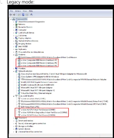
The following pictures show how the interface is recognized on Windows systems: 1. Legacy mode:
Figure 5: Legacy mode on WIndows system
The Windows system recognizes 6 CDC-ACM interfaces: 3 of them are AT command interface. The additional 3 CDC-ACM interfaces are used for special purposes: GPS Virtual Port, Mobile Diagnostic Virtual Port and SIM Access Profile (SAP) Virtual Port.
2. CDC-ECM mode:
Figure 6: CDC-ECM mode on Linux system
The Linux system recognizes one CDC-ECM interface (eth1 interface in the list of network devices), and 3 CDC-ACM (3 AT command interface).
UBX-14000479 - R03 Early Production Information Additional information
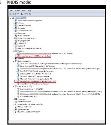
3. RNDIS mode:
Figure 7: RNDIS mode on Windows system
The Windows system recognizes one RNDIS interface and one CDC-ACM interface (AT command interface). The PPP connections may be established for every USB profile, since at least one CDC-ACM is available in every one.
UBX-14000479 - R03 Early Production Information Additional information
5.2
Dial-up connection
The module is able to perform dial-up connections supporting the Point Protocol (PPP). The Point-to-Point Protocol provides a standard method for transporting multi-protocol datagrams over point-to-point links. The PPP connection is established between the target and the DTE in both router and bridge modes. In particular, the target performs as the PPP server, while the DTE performs as the PPP client.
The target supports both active and passive PPP negotiation modes. In active mode the server sends the first LCP Configuration Request message without waiting for the PPP client to do so, while in the passive mode the server waits for the PPP client to send the first LCP Configuration Request message before sending its own Configuration Request message. The target operates by default in passive mode. If the client does not send the first LCP packet within a given period (1 s), then the server (cellular module) will send the first LCP packet to the client. In particular, the value of the timeout is set to 1 s. If no LCP Configuration Response is received the request is repeated for at most ten times. The LCP Configuration Request is sent every one second.
It is worth noticing, that the number of dial-up connection depends on the active USB profile on the target. In the “High Throughput Profile” (AT+UUSBCONF=3,"RNDIS") there is only one CDC-ACM interface, hence only one dial-up connection can be established. In the “Low/Medium Throughput Profile” (AT+UUSBCONF=2,"ECM") there are three CDC-ACM interfaces for AT commands and data, hence at most three dial-up connections can be established. In the “Fairly back-compatible Profile” (AT+UUSBCONF=0) there are six CDC-ACM interfaces, but only the three of them are available for AT commands and data, therefore at most three dial-up connections can be established.
A PPP dial-up connection can be started on an already active PDP context/EPS bearer only when the TOBY-L2 module is in the “Fairly back-compatible Profile” (USB profile defined with AT+UUSBCONF=0). In the case of the LTE networks, this implies that the initial default EPS bearer, which is always established at the time of attachment to the LTE network, is suitable for dial-up connections on the module. Also note that the already active PDP context/EPS bearer should be provided with the network/internet connectivity so that the PPP also has the connectivity. In this case the activation of a PPP session over an already active CID will move to connectivity for the previous configuration to the PPP session. Depending on the network provider policy for LTE networks, the cellular connectivity configuration requests the use of the +UCGDFLT AT command.
A dial-up acquires exclusive access to a PDP context: therefore it should be noted that activating a PPP session over an already active CID will disrupt connectivity for the previous user (if present).
The following example refers to an attempt of dial-up connection when the module attached to a 4G network: 1. The module is in router mode.
2. The module is in “Fairly back-compatible Profile” and it has +UCGDFLT’s APN configured for internet connectivity.
3. The TOBY-L2 IP subsystem is configured to access the internet through the cellular network within an internal context.
4. The module registers on a LTE network: the initial PDP context is activated on CID 4. 5. The initial PDP context is providing connectivity for the TOBY-L2 IP subsystem. 6. The dial-up session is started over the already active CID 4:
o The PPP session now has exclusive access to the initial PDP connectivity;
o The TOBY-L2 IP subsystem has no access to the internet and it must be reconfigured to use a different PDP context (if possible).
7. In order to give internet connectivity to both PPP and TOBY-L2 IP subsystem through the cellular network, two PDP contexts must be used.
In addition, also a further example is provided for the case of the module attached to a 2G/3G network: 1. The module is in router mode.
UBX-14000479 - R03 Early Production Information Additional information
3. The TOBY-L2 IP subsystem is configured to access the internet through the cellular network within an internal context (defined and activated).
4. The active PDP context is providing connectivity for the TOBY-L2 IP subsystem. 5. The dial-up session is started over the already active context:
o The PPP session now has exclusive access to the initial PDP connectivity;
o The TOBY-L2 IP subsystem has no access to the internet and it must be reconfigured to use a different PDP context (if possible).
6. In order to give internet connectivity to both PPP and TOBY-L2 IP subsystem through the cellular network, two PDP contexts must be used.
Figure 8 shows the dial-up connection in bridge mode and “Low/Medium Throughput Profile”, while Figure 9 shows the coexistence between one dial-up connection and two active PDP context/EPS bearer when “Fairly back-compatible Profile” is active.
NAT IP Stack
C D C -A C M
DNS
2.6.123.54
Internet WAN
8.8.8.8
GGSN
Mobile WAN
DTE
PPP
PPP
V I R I N T
UBX-14000479 - R03 Early Production Information Additional information
NAT IP Stack
. . . .
R N D I S DHCP DNS V I R I N T V I R I N T 192.168.1.100 192.168.1.1 120.34.86.3 2.6.123.54 DTE• IPv4 address
• IPv4 network mask
• Ipv4 gateway
• DNS server
Mobile WAN Internet WAN 8.8.8.8 GGSN1 GGSN2 PPP C D C -A C M V I R I N T PPP GGSN3 240.74.36.9
Figure 9: 3 PDP contexts, one PPP (router mode)
5.2.1
Dial-up PPP configuration on Linux systems
On Linux platforms the PPP connection shall be established with “wvdial”, which is a text-based dial-up application. The following configuration script shall be used to activate a PPP connection on the CID number
<cid>.
[Dialer Defaults] Modem Type = USB Modem ISDN = 0
Init1 = ATZ
Init2 = AT+CGDCONT=<cid>,"IP",<apn> Modem = /dev/ttyACM<X>
Baud = 460800
Phone = *99***<cid># ; Username = <Login Name> ; Password = <Password>
In the script, <cid> represents the cid on which the PPP connection should be activated, <apn> is the APN name of the configured context, and /dev/ttyACM<X> represents the name of the device recognized by the system. Some mobile operators could also request a login name and a password, <Login Name> and <Password> respectively. The semicolon, indicating that the line is a comment, should be removed to specify the login and password parameters.
UBX-14000479 - R03 Early Production Information Additional information
5.2.2
Dial-up PPP configuration on Windows systems
On Windows systems, a new dial-up connection should be configured via the menu:
Start > Control Panel > Network and Sharing Center > Set up a new connection or network
The configuration procedure requires the selection of the target (modem device) and the number to dial. On Windows systems the configuration of the context should be performed manually via AT command or through Windows modem properties. For example, to set the APN name on context 1 the user should specify the AT command:
at+cgdcont=1,"IP","<apn>"
UBX-14000479 - R03 Early Production Information Additional information
Figure 10: Dial-up Connection Windows Figure 11: Properties > General tab
UBX-14000479 - R03 Early Production Information Additional information
Figure 14: Properties > Security tab
5.3
Local dial-up connection
TOBY-L2 modules support the local dial-up connection. This feature allows modules to establish an IP-based connection with an external application processor through CDC-ACM, UART or MUX interfaces. During the local dial-up, a point to point connection is created between the TOBY-L2 IP stack and the external application processor IP stack. The established connection is denoted by two IP addresses belonging to the same private subnetwork. Two IP addresses are required, one for each ending of the dial-up connection. The subnetwork, defined for the local dial-up, should be different from the subnetworks used for RNDIS/CDC-ECM interfaces. The local dial-up assigns to the host also the DNS server IP address. The IP address of the specified DNS server is equal to the local dial-up IP address of the target. In this configuration the target is performing as the DNS server for the host. If a different DNS server is requested, it should be defined by the customer during the IP network configuration of the host. Figure 15 shows the IP connections when the local dial-up feature is enabled on one MUX interface.
The local dial-up feature can be used when:
the external processor does not have an RNDIS/CDC-ECM interface, and it is provided with an IP stack the IP connectivity between the UART and RNDIS/CDC-ECM interfaces is requested
only one PDP context/EPS bearer shall be used to provide internet connectivity to the external processor through the UART or RNDIS/CDC-ECM interfaces
The ATD*99***100# command activates the local dial-up feature. The CID number 100 does not conflict with the CIDs used for dial-up connections, which are related to PDP contexts/EPS bearers.
Follow these operations to obtain the internet connectivity on the external processor through two MUX interfaces:
a) activate two MUX interfaces on UART
b) activate the local PPP on one of the virtual port by sending the ATD*99***100# command c) use the second virtual ports for sending AT commands
UBX-14000479 - R03 Early Production Information Additional information
d) activate one PDP context (+CGDCONT, +CGACT) or use the EPS bearer (+UCGDFLT):
a. if after boot the module is registered on 4G network, check that the default bearer has IP connectivity, if not, configure the APN with +UCGDFLT
b. if after boot the module is registered on 3G or 2G network, define a PDP context (+CGDCONT) and activate it (+CGACT)
NAT IP Stack
. . . .
R N D I S DHCP DNS V I R I N T 192.168.1.100 192.168.1.1 120.34.86.3 DTE• IPv4 address
• IPv4 network mask
• Ipv4 gateway
• DNS server
Mobile WAN Internet WAN 8.8.8.8 GGSN1 PPP U A R T PPP M U X M U X 192.168.10.1 192.168.10.2
Figure 15: Local dial-up connection on one MUX interface in router mode
5.4
Multiple PDP contexts/EPS bearers
In LTE, PS data connections are referred to as ESP bearers: EPS bearers are conceptually equivalent to the legacy PDP contexts, which are often referred to for the sake of simplicity.
Similarly to a PDP context, the EPS bearer can be a default (primary) or dedicated (secondary) one. The initial EPS bearer established during LTE Attach procedure is actually a default EPS bearer.
When attached to an LTE network with some mobile operators, it may occur that the activation of user-defined EPS default bearers is rejected by the network. In this case the connectivity may be granted by the default initial EPS bearer when it is configured as an initial PDP context (+UCGDFLT AT command) and using the module in route mode through the RNDIS interface. Using the module in the “Fairly back-compatible Profile”, a PPP connection may be performed on an active default initial EPS bearer configured as an initial PDP context. Check the user-defined EPS bearers availability with the current mobile network operator.
If the initial default EPS bearer is not suitable for internet connectivity, like on Verizon network where is it devoted to IMS services, activate a second default EPS bearer with appropriate APN to enable PS data services. This can be automatically done by the module on Verizon network (see AT+UMNOCONF command). In Verizon configuration, if the IMS APN gives no IP/IPv6 connectivity or the LTE attach fails, then the module will automatically select the internet APN and perform the LTE attach with it.
UBX-14000479 - R03 Early Production Information Additional information
5.4.1
Module cellular connectivity in relation to the USB interface profile and
networking mode
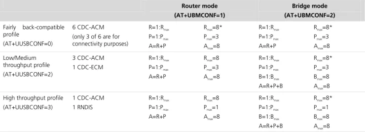
The module is able to handle a maximum of eight contexts. However, the context configuration depends on the USB interface profile and on the networking modes.
As reported in section 5.1.6, the module offers three USB interface profiles: a fairly backwards-compatible profile, a low/medium throughput profile and a high throughput profile. In the first USB profile there are six CDC-ACM interfaces, but only three of them can be used for connectivity purposes. The second profile provides three CDC-ACM interfaces (all of them can be used for connectivity purposes) and one CDC-ECM interface. The last profile offers only one CDC-ACM interface and one RNDIS interface.
The TOBY-L2 module can operate in two different networking modes: router and bridge mode. The complete description is provided in sections 2 and 3. The context configuration is done accordingly to the networking mode.
Furthermore, when the module is in bridge mode, the contexts can be reconfigured in router mode using the command +UDPDP. In this case the target becomes the context’s owner to have internal connectivity.
In both networking modes, the PPP connections are one-to-one to the number of available CDC-ACM interfaces used for connectivity purposes.
Table 1 summarizes the configuration of the PDP contexts in relation to the USB profile and the networking mode.
Router mode (AT+UBMCONF=1)
Bridge mode (AT+UBMCONF=2)
Fairly back-compatible profile
(AT+UUSBCONF=0)
6 CDC-ACM (only 3 of 6 are for connectivity purposes)
R=1:Rmax
P=1:Pmax
A=R+P
Rmax=8*
Pmax=3
Amax=8
R=1:Rmax
P=1:Pmax
A=R+P
Rmax=8*
Pmax=3
Amax=8 Low/Medium throughput profile (AT+UUSBCONF=2) 3 CDC-ACM 1 CDC-ECM R=1:Rmax P=1:Pmax A=R+P
Rmax=8
Pmax=3 Amax=8
R=1:Rmax
P=1:Pmax B=1:Bmax A=R+P+B
Rmax=8*
Pmax=3 Bmax=8 Amax=8 High throughput profile
(AT+UUSBCONF=3) 1 CDC-ACM 1 RNDIS R=1:Rmax P=1:Pmax A=R+P
Rmax=8 Pmax=1 Amax=8
R=1:Rmax P=1:Pmax B=1:Bmax
A=R+P+B
Rmax=8* Pmax=1 Bmax=8
Amax=8
Table 1: Contexts configuration in relation to the USB profile and the networking mode where:
R = context in router mode
Rmax = maximum number of contexts in router mode
P = PPP session (one to one to CDC-ACM interface) Pmax = maximum number of PPP sessions
B = context in bridge mode
Bmax = maximum number of contexts in bridge mode
A = total number of contexts Amax = maximum number of contexts
UBX-14000479 - R03 Early Production Information Appendix
Appendix
A
IP subsystem configuration
This appendix provides the most important shell commands needed to configure the IP subsystem of a generic Windows and Linux operating system.
This convention used in the following IPv4 examples is: A1.A2.A3.A4 denotes an IPv4 address
abcX is the name of the interface in a Linux OS Y is the number of the virtual interface in Linux OS G1.G2.G3.G4 is the IPv4 gateway
N1.N2.N3.N4/M denotes an IPv4 subnetwork M is the size of the IPv4 subnetwork bit field
M1.M2.M3.M4 is the mask in dotted decimal notation Ifname is the name of the interface under Windows Ifnum is the number of the interface under Windows
and DNS1 is the IPv4 address of the DNS server in dotted-decimal notation
Moreover, the IPv6 address is 128 bit long and it is subdivided in 64-bit prefix (PREFIX_64) and 64-bit suffix (SUFFIX_64). Each network device has its local IPv6 address, which typically looks like FE80::SUFFIX_64, where FE80::/64 is the link local prefix (LINKLOCAL_64). Each network interface sends a Router Solicitation message in order to find the next hop router. The next hop router will reply with a Router Advertisement message. The Router Advertisement message will contain the PREFIX_64, which is used by the network interface to define its global IPv6 address (PREFIX_64:SUFFIX_64). The IPv6 gateway will have the GW_PREFIX_64:GW_SUFFIX_64 address, while IPv6_SUBNET denotes a specific IPv6 subnetwork.
A.1
IPv4 interface configuration in Windows OS
Example ID DOS command Explanation
1 netsh int ip add address name=”Ifname”
addr=A1.A2.A3.A4 mask= M1.M2.M3.M4 Set the IP address of the interface Ifname and of the virtual interface of Ifname
2 netsh int ip del address name=”Ifname”
addr=A1.A2.A3.A4
Unset the IP address of the interface Ifname and of the virtual interface of Ifname
3 route ADD 0.0.0.0 MASK M1.M2.M3.M4 G1.G2.G3.G4 METRIC
1 IF Ifnum Set default gateway
4 route DELETE 0.0.0.0 G1.G2.G3.G4 Unset the default gateway
5 route ADD N1.N2.N3.N4 MASK M1.M2.M3.M4 G1.G2.G3.G4 IF
Ifnum Set a gateway for a specific network
6 route DELETE N1.N2.N3.N4 Unset a gateway for a specific network
7 netsh int ip add dns name=”Ifname” addr=DNS1 Set a DNS server
8 netsh int ip del dns name=”Ifname” addr= DNS1 Unset a DNS server
A.2
IPv4 interface configuration in Linux OS
Example ID Bash command Explanation
1 ifconfig abcX A1.A2.A3.A4 Set the IP address of the interface abcX
2 ifconfig abcX:Y A1.A2.A3.A4 netmask M1.M2.M3.M4
pointopoint G1.G2.G3.G4 up
or
Set the IP address of the virtual interface Y of abcX (in bridge mode see the note how to obtain gateway address). The keywords
UBX-14000479 - R03 Early Production Information Appendix
Example ID Bash command Explanation
ip addr add A1.A2.A3.A4/M peer G1.G2.G3.G4 dev abcX “pointopoinit” and “peer” enables the point-to-point mode of an interface, meaning that it is a direct link between two machines with nobody else listening on it
3 route add default gw G1.G2.G3.G4 Set default gateway
4 route del default Unset the default gateway
5 route add –net N1.N2.N3.N4/M gw G1.G2.G3.G4 Set a gateway for a specific network
6 route del –net N1.N2.N3.N4/M gw G1.G2.G3.G4 Unset a gateway for a specific network
7 echo “nameserver DNS1” >> /etc/resolv.conf Set a DNS server
A.3
IPv6 interface configuration in Windows OS
Example ID DOS command Explanation
1 netsh interface ipv6 add address
“Ifname”LINKLOCAL_64:SUFFIX_64 Set the IPv6 link local address of the interface Ifname
2 netsh interface ipv6 add address “Ifname”
PREFIX_64:SUFFIX_64 Set the IPv6 global address of the interface Ifname
3 netsh interface ipv6 del address “Ifname”
LINKLOCAL_64:SUFFIX_64
Unset the IPv6 link local address of the interface Ifname
4 netsh interface ipv6 del address “Ifname”
PREFIX_64:SUFFIX_64 Unset the IPv6 global address of the interface Ifname
5 netsh interface ipv6 add route IPv6_SUBNET “Ifname”
GW_PREFIX_64:GW_SUFFIX_64
Set gateway on the interface Ifname for subnetwork IPv6_SUBNET
6 netsh interface ipv6 del route IPv6_SUBNET “Ifname”
GW_PREFIX_64:GW_SUFFIX_64 Unset gateway on the interface Ifname for subnetwork IPv6_SUBNET 7 netsh interface ipv6 add dnsserver “Ifname” DNS-IPv6 Set a DNS server on the interface Ifname 8 netsh interface ipv6 del dnsserver “Ifname” DNS-IPv6 Unset a DNS server on the interface Ifname
9 netsh interface ipv6 add neighbors “Ifname”
RANDOM-SUFFIX_64 Prevent Neighbor Discovery on the interface Ifname, by adding a neighbor with a random IPv6 address
10 netsh int ipv6 set privacy state=disabled/enabled Disable/enable IPv6 privacy extensions. Used with example ID 11.
11 netsh interface ipv6 set global
randomizeidentifiers=disabled store=active netsh interface ipv6 set global
randomizeidentifiers=disabled store=persistent
Disable random generation for non-temporary autoconfigured IPv6 addresses. The IPv6 addresses are based on IEEE EUI-64 12 netsh int ipv6 set interface "Ifname"
routerdiscovery=disabled/enabled Disable/enable sending Router Solicitation
13 netsh int ipv6 set interface "Ifname"
advertise=disabled/enabled Disable/enable sending Router Advertisement
With the netsh option store=active the changes are applied for the current session, while with the option store=persistent the changes are applied permanently.
A.4
IPv6 interface configuration in Linux OS
Example ID Bash command Explanation
1 ip -6 addr add LINKLOCAL_64:SUFFIX_64 dev abcX Set the IPv6 link local address of the interface abcX
2 ip -6 addr add PREFIX_64:SUFFIX_64 dev abcX Set the IPv6 global address of the interface abcX
3 ip -6 addr del LINKLOCAL_64:SUFFIX_64 dev abcX Unset the IPv6 link local address of the interface abcX
UBX-14000479 - R03 Early Production Information Appendix
Example ID Bash command Explanation
interface abcX
5 ip -6 route add IPv6_SUBNET via
GW_PREFIX_64:GW_SUFFIX_64 Set gateway on the interface abcX
6 ip -6 route del IPv6_SUBNET via
GW_PREFIX_64:GW_SUFFIX_64 Unset default gateway on the interface abcX
7 echo “nameserver DNS-IPv6” >> /etc/resolv.conf Set a DNS server
8 delete the related row from the file
/etc/resolv.conf Unset a DNS
9 ip neigh add GW_PREFIX_64:RANDOM_SUFFIX_64 lladdr
RANDOM_MAC_ADDR dev abcX In bridge mode on host side: prevent Neighbor Discovery on the interface abcX, by adding a fictitious neighbor with a random IPv6 address
10 ip neigh del GW_PREFIX_64:RANDOM_SUFFIX_64 lladdr
RANDOM_MAC_ADDR dev abcX In bridge mode on host side: delete the fictitious neighbor associated with the interface abcX
11 ip neigh show In bridge mode on host side: show the list of
the neighbor
12 In /etc/radvd.conf:
AdvSendAdvert off|on Disable/enable sending Router Advertisement and Router Solicitation 13 sudo sysctl –w net.ipv6.conf.all(abcX).autoconf=0 Autoconfigure addresses using prefix
information from router advertisements
14 sudo sysctl –w
net.ipv6.conf.all(abcX).use_tempaddr=<value> Disable random generation for non-temporary autoconfigured IPv6 addresses. The IPv6 addresses are based on IEEE EUI-64. This option disable/enable IPv6 privacy extensions. <value> can be chosen from the following:
<=0 Disable Privacy Extensions (i.e. do not use changing temporary addresses at all)
==1 Use the Privacy Extensions, but prefer public (i.e. non-temporary) addresses over temporary ones.
>1 (e.g. 2 as here) Use the Privacy Extensions and prefer them.
UBX-14000479 - R03 Early Production Information Appendix
B
Router/Bridge mode configuration in Linux
The example setup has been performed on a Linux machine running Ubuntu 14.04 distribution. In Router mode the following setting shall be used in Linux:
Open a terminal
Identify the interface associated with the USB virtual Ethernet (i.e. usb1). Input ifconfig, the RNDIS is not active yet
Input dhcclient usb1 to configure the DHCP client, now the USB virtual Ethernet interface is active Input ifconfig and check that USB virtual Ethernet is active
In Bridge mode the following setting shall be used in Linux: Precondition: a data context is already active on the module
For example 100.87.53.78 is the IP address obtained with +CGDCONT (or + CGCONTRDP), usb1 is the interface associated to RNDIS and 100.87.53.177 is the virtual IP that is obtained with +UIPADDR
Open a terminal
Input killall dhclient
Input ifconfig usb1 192.168.1.149 netmask 255.255.255.0
ping 192.168.1.1 (it is possible to ping the module)
ping 8.8.8.8 (it will return an error because the routing rules are missing)
ifconfig usb1:0 100.87.53.78 netmask 255.255.255.255 pointopoint 100.87.53.177 up (similar to ‘alias’ in Windows, ‘pointopoint’ sets up a two hosts network with the module)
ping 8.8.8.8 (it will return an error because we need to specify how to route the traffic) route add default gw 100.87.53.177
ping 8.8.8.8 (it is possible to ping an external address) ifconfig usb1 down (it closes the RNDIS interface)
UBX-14000479 - R03 Early Production Information Appendix
C
List of acronyms
Abbreviation / Term Explanation / Definition
ARP Address Resolution Protocol DHCP Dynamic Host Configuration Protocol EPS Evolved Packet System
IPv4 Internet Protocol version 4 IPv6 Internet Protocol version 6 MAC Media Access Control NDP Neighbor Discovery Protocol NVM Non Volatile Memory
UBX-14000479 - R03 Early Production Information Related documents
Related documents
[1] u-blox AT Commands Manual, Docu No UBX-13002752
[2] u-blox AT Commands Examples Application Note, Docu No UBX-13001820 [3] Charles M. Kozierok – “The TCP/IP Guide” – No Starch Press
[4] Andrew S. Tanenbaum – “Computer Networks (5th Edition)” – Prentice Hall
[5] RFC 2131, Dynamic Host Configuration Protocol, https://www.ietf.org/rfc/rfc2131.txt [6] RFC 1661 The Point-to-Point Protocol (PPP), ftp://ftp.rfc-editor.org/in-notes/rfc1661.txt
[7] RFC 4861 Neighbor Discovery for IP version 6 (IPv6), ftp://ftp.rfc-editor.org/in-notes/rfc4861.txt [8] RFC 4862 IPv6 Stateless Address Autoconfiguration, ftp://ftp.rfc-editor.org/in-notes/rfc4862.txt [9] RFC 5072, IP Version 6 over PPP, ftp://ftp.rfc-editor.org/in-notes/rfc5072.txt
[10] RFC 5075 IPv6 Router Advertisement Flags Option, ftp://ftp.rfc-editor.org/in-notes/rfc5075.txt [11] RFC 6106 IPv6 Router Advertisement Options for DNS Configuration
ftp://ftp.rfc-editor.org/in-notes/rfc6106.txt
[12] RFC 6459 IPv6 in 3rd Generation Partnership Project (3GPP) Evolved Packet System (EPS), ftp://ftp.rfc-editor.org/in-notes/rfc6459.txt
For regular updates to u-blox documentation and to receive product change notifications please register on our homepage.
Revision history
Revision Date Name Status / Comments
R01 29-Oct-2014 ador Initial release
R02 30-Jan-2015 mace Added some suggestion on Connection Manager development and kernel recompiling R03 17-Jul-2015 mace Added local PPP description
UBX-14000479 - R03 Early Production Information Contact
Contact
For complete contact information visit us at www.u-blox.com u-blox Offices
North, Central and South America
u-blox America, Inc.
Phone: +1 703 483 3180 E-mail: [email protected]
Regional Office West Coast:
Phone: +1 408 573 3640 E-mail: mailto:[email protected]
Technical Support:
Phone: +1 703 483 3185
E-mail: mailto:[email protected]
Headquarters
Europe, Middle East, Africa
u-blox AG
Phone: +41 44 722 74 44 E-mail: [email protected] Support: mailto:[email protected]
Asia, Australia, Pacific
u-blox Singapore Pte. Ltd.
Phone: +65 6734 3811 E-mail: [email protected] Support: [email protected]
Regional Office Australia:
Phone: +61 2 8448 2016 E-mail: [email protected] Support: [email protected]
Regional Office China (Beijing):
Phone: +86 10 68 133 545 E-mail: [email protected] Support: [email protected]
Regional Office China (Shenzhen):
Phone: +86 755 8627 1083 E-mail: [email protected] Support: [email protected]
Regional Office India:
Phone: +91 959 1302 450 E-mail: mailto:[email protected] Support: mailto:[email protected]
Regional Office Japan:
Phone: +81 3 5775 3850 E-mail: [email protected] Support: [email protected]
Regional Office Korea:
Phone: +82 2 542 0861 E-mail: [email protected] Support: [email protected]
Regional Office Taiwan:
Phone: +886 2 2657 1090 E-mail: [email protected] Support: [email protected]