PERFORMANCE STUDY OF AIR INTERFACE FOR
BROADBAND WIRELESS PACKET ACCESS
PENG XIAOMING
NATIONAL UNIVERSITY OF SINGAPORE
I
ACKNOWLEDGEMENTS
I owe my gratitude to all the people who have made this thesis possible and because of whom my graduate experience has been one that I will cherish forever.
First and foremost I would like to thank my advisor, Dr. Francois Chin, who has given me an invaluable opportunity to do research and work on challenging and extremely interesting subjects over the past four years. He has always made himself available for help and advice. His tireless support, advice, and discussions have greatly helped me to successfully complete this research thesis.
Thanks are due to Professor C. C. Ko for sharing his invaluable research experience and reviewing manuscripts.
All my colleagues and friends have enriched my graduate study in many ways. I would like to thank my colleagues at the Wireless Communications Department of Institute for Infocomm Research for their interesting discussions and insights.
I owe my deepest thanks to my family: my wife zhaoxia and my son shixin who have always support and understand me through my study. I thank my parents for their encouragement, support, and understanding through all these years.
I also would like to thank all my brothers and sisters from my church for their constant support and encouragement through all these years.
Last but not least, I would like to express the biggest thanks to GOD, who has constantly guidance, lead me during my difficult moments.
II
TABLE OF CONTENTS
ACKNOWLEDGEMENTS ... I
SUMMRY ...
V
LIST OF SYMBOLS ... VII
LIST OF FIGURES ...
X
LIST OF TABLES ... XIV
1
INTRODUCTION ... 1
1.1 Overview of Air Interface for Broadband Wireless Packet Access ... 1
1.2 Organization of Thesis and Contributions ... 10
2
BLOCK SPREAD CDMA ... 13
2.1 Introduction ... 13
2.2 Block Spread ... 15
2.3 Block Spread CDMA (BS-CDMA) ... 17
2.4 BS-CDMA with Interference Cancellation ... 34
2.5 Simulation Results and Discussions ... 37
2.6 Chapter Summary ... 48
3
TWO-LAYER SPREADING CDMA ... 49
3.1 Introduction ... 49
3.2 Two-Layer Spreading CDMA (TLS-CDMA) ... 50
III
3.4 Chapter Summary ... 83
4
BLOCK SPREAD INTERLEAVED FREQUENCY DIVISION
MULTIPLE ACCESS (BS-IFDMA) ... 85
4.1 Introduction ... 85
4.2 Block Spread Interleaved Frequency Division Multiple Access (BS-IFDMA) ... 86
4.3 BS-IFDMA with Interference Cancellation ... 96
4.4 Simulation Results and Discussions ... 102
4.5 Chapter Summary ... 108
5
TWO-DIMENSIONAL CODE SPREADING INTERLEAVED
FREQUENCY DIVISION MULTIPLE ACCESS
(TCS-IFDMA) ... 109
5.1 Introduction ... 109
5.2 Two-dimensional Code Spreading IFDMA (TCS-IFDMA) ... 111
5.3 Simulation Results and Discussions ... 123
5.4 Chapter Summary ... 128
6
MULTI-BAND UWB SCHEME: A NEW AIR INTERFACE
OVER ULTRA-WIDE SPECTRUM ... 129
6.1 Introduction ... 129
6.2 Multi-band UWB Scheme using Over-sampling Multi-channel Equalization ... 138
6.3 Simulation Results and Discussions ... 148
6.4 Chapter Summary ... 151
7
CONCLUSIONS AND FUTURE RESEARCH ... 153
IV
7.2 Future Research ... 158
BIBLIOGRAPHY ... 159
V
SUMMARY
Broadband wireless packet access with an all-IP architecture has emerged as the preferred platform to deliver higher data rates and provide more diverse services than the current wireless systems. Therefore, the design of a flexible and scalable new air interface has to take into account the fact that the dominant wireless traffic load will be high-speed and bursty in nature. This poses great challenges to the existing air interface technologies.
This thesis investigates various means to cope with this design challenge. Firstly, a new concept of using block spread (BS) is proposed to deal with multi-user interference for high data rate transmission. This achieves near single user performance without using complex multi-user detection (MUD) techniques because the code orthogonality of BS is easily maintained when the channel variation across the consecutive blocks, in a block by block high data rate transmission, is negligible. Specifically, a block-spread code division multiple access (BS-CDMA) scheme is proposed to combat multiple access interference (MAI) and multipath interference (MPI) for uplink transmission, giving rise to a significantly improved multi-user performance in a broadband wireless channel. Extending the concept of BS, we have investigated a two-layer spreading CDMA (TLS-CDMA) scheme, in which an additional two-layer cell-specific scrambling code is used to tackle other cell interference (OCI) and achieve a lower data rate for higher-quality transmission in a multi-cell system. With analytical and simulation results showing their superiority over the existing single carrier scheme, these two schemes can enhance the performance of the conventional DS-CDMA system.
VI for multi-user allocation. In particular, a block spread interleaved frequency division multiple access (BS-IFDMA) scheme has been formulated to use this additional domain to support more users on top of the IFDMA domain. With the priority of allocating multiple users in the block spread code domain and then in frequency, BS-IFDMA can achieve larger frequency diversity than the conventional IFDMA scheme for the same number of users and bandwidth when the channel variation across the consecutive block is negligible. Two interference cancellation methods based on users’ mobility have been proposed to enhance its performance when the channel variation across the consecutive blocks is not negligible. In addition, a two-dimensional code spreading IFDMA (TCS-IFDMA) scheme, which uses the BS concept for additional multi-users allocation, has also been proposed to combat MAI and OCI more efficiently. The analysis and simulation studies show that the proposed TCS-IFDMA scheme enhances the variable spreading and chip repetition factor
CDMA (VSCRF-CDMA) scheme significantly by prioritizing users in the time
domain spreading according to the cell structure, channel conditions and the active number of users. It can realize seamless handover between the cellular system and the hot-spot system using the same air interface deployed.
Lastly, this thesis also deals with the design of air interface over ultra-wideband (UWB) channel (>500MHz bandwidth) with dense multipaths. A multi-band UWB system using over-sampling multi-channel equalizer has been proposed to transmit ultra-high data rate at low cost and power. Through detailed analytical and simulation studies, the proposed scheme is shown to be able to handle inter-symbol interference (ISI) and harness the rich multipath diversity under any channel conditions.
VII
LIST OF SYMBOLS
AMPS: Advanced Mobile Phone System ARQ: Automatic Repeat reQuest
AWGN: Additive White Gaussian Noise
BER: Bit Error Rate
BPSK: Binary Phase Shift Keying BS: Block Spread
BS-CDMA: Block Spread Code Division Multiple Access CCR: Chip-Compression-and-Repetition
CDMA: Code Division Multiple Access
CE: Cyclic Extension
CLI: Chip Level Interleaving CP Cyclic Prefix
CP-CDMA: Cyclic Prefix CDMA CRF: Chip-Repetition Factor
CSF: Code-domain Spreading Factor DS-CDMA: Direct Sequence CDMA
DS-UWB: Direct Sequence Ultra-Wideband EGC: Equal Gain Combining
FCC: Federal Communication Commission FDE Frequency Domain Equalization
FDMA: Frequency Division Multiple Access
FFT: Fast Fourier Transform
FOMA: Freedom Of Mobile multi-media Access
GSM: Global System for Mobile communications HMC: Hybrid MAI Cancellation
HSDPA: High Speed Downlink Packet Access HSUPA: High Speed Uplink Packet Access
IFDMA: Interleaved Frequency Division Multiple Access IFFT: Inverse FFT
ICI: Inter-Chip Interference ISI: Inter-Symbol Interference
VIII MB-OFDM: Multi-Band Orthogonal Frequency Division Multiplexing MC-CDMA: Multi-Carrier CDMA
MC-DS-CDMA: Mutli-Carrier Direct Sequence CDMA
MIMO: Multiple Input and Multiple Output
MLSE: Maximum-Likelihood Sequence Estimation
MMSE: Minimum Mean Squared Errors MPI: Multi-Path Interference
MRC: Maximum Ratio Combining
MSMC Multistage Successive MAI cancellation MUD: Multi-User Detection
OCI: Other-Cell Interference
OFCDM: Orthogonal Frequency Code Division Multiplexing
OFDM: Orthogonal Frequency Division Multiplexing
OFDMA: Orthogonal Frequency Division Multiplexing Access PAPR: Peak-to-Average Power Ratio
PAM: Pulse Amplitude Modulation PPM: Pulse Position Modulation PRI: Pulse Repetition Interval PSD: Power Spectrum Density QPSK: Quadrature Phase Shift Keying
RTD: Round Trip Delay
SC-FDE: Single Carrier Frequency Domain Equalization SMC: Serial MAI Cancellation
SF: Spreading Factor
TACS: Total Access Communication System
TCS-IFDMA: Two-dimensional Code Spreading for IFDMA TDD: Time-Division Duplex
TDE: Time Domain Equalization
TDMA: Time Division Multiple Access
TD-SCDMA: Time Division Synchronized CDMA TFL-CDMA: Time Frequency Localized CDMA TLS-CDMA: Two-Layer Spreading CDMA UWB: Ultra-Wide Band
VSCRF-CDMA: Variable Spreading and Chip Repetition Factor CDMA VSF-OFCDM: Variable Spreading Factor-Orthogonal Frequency Code
IX Division Multiplexing
WBAN: Wireless Body Area Network
WLAN: Wireless Local Area Network WPAN: Wireless Personal Area Network WUSB: Wireless Universal Serial Bus
X
LIST OF FIGURES
FIGURE 1-1 ITU-R VISION FOR 4G/B3G SYSTEMS ...6 FIGURE 1-2 ROADMAP OF 4G SYSTEM ...6 FIGURE 2-1 PACKET STRUCTURE FOR HIGH DATA RATE SYSTEM ...16 FIGURE 2-2 TRANSFER FUNCTION OF BROADBAND WIRELESS
CHANNEL ...17 FIGURE 2-3 BLOCK DIAGRAM OF THE PROPOSED BS-CDMA SYSTEM ...19 FIGURE 2-4 INPUT AND OUTPUT DATA STRUCTURE OF BLOCK
SPREADING AND SCRAMBLING MODULE ...20 FIGURE 2-5 THE DATA STRUCTURE AFTER PARALLEL-TO-SERIAL
CONVERSION ...20
FIGURE 2-6 THE DATA STRUCTURE AFTER INSERTION OF CE (CE1A IS
CYCLIC PREFIX AND CE1B IS CYCLIC POSTFIX OF BLOCK 1)
...20 FIGURE 2-7 THE ILLUSTRATION OF CE HANDLING MULTI-USER
ASYNCHRONOUS UPLINK TRANSMISSION (THREE USERS) ..20 FIGURE 2-8 THE DETAILED PROCEDURE OF BLOCK DESCRAMBLING
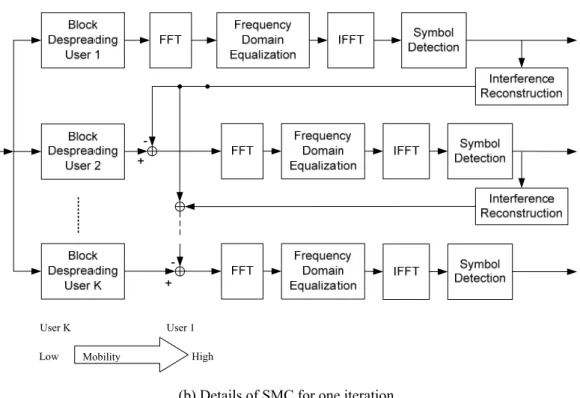
AND DISPREADING ...26 FIGURE 2-9 THE ITERATIVE SMC METHOD FOR THE BS-IFDMA
SCHEME WITH U=K ...37 FIGURE 2-10 THE MULTISTAGE SMC METHOD FOR THE BS-IFDMA
SCHEME WITH U=K (THREE GROUPS) ...37 FIGURE 2-11 EXAMPLE OF CHANNEL RESPONSE ACROSS TIME (TWO
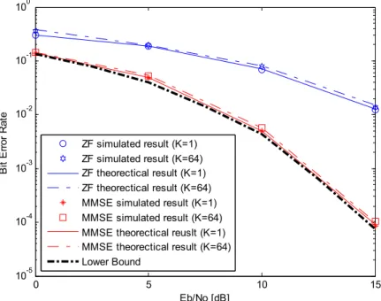
PACKET LENGTH) WITH DIFFERENT USER MOBILITY ...39 FIGURE 2-12 SIMULATED AND THEORETICAL PERFORMANCE OF THE
BS-CDMA SYSTEM ...41 FIGURE 2-13 PERFORMANCE OF THE BS-CDMA SYSTEM FOR BOTH
16 QAM AND 64 QAM ...41 FIGURE 2-14 THE EFFECT OF DOPPLER SPREAD ON THE BS-CDMA
SYSTEM ...43 FIGURE 2-15 SYNCHRONIZATION EFFECT ON THE BS-CDMA SYSTEM
(QPSK, 16QAM) ...44 FIGURE 2-16 PERFORMANCE COMPARISONS AMONG BS-CDMA,
XI CP-CDMA AND DS-CDMA SYSTEMS FOR BOTH QPSK
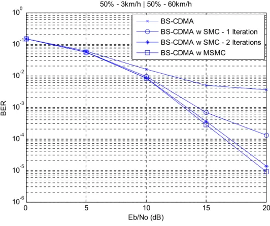
AND 16QAM IN A MULTI-CELL SYSTEM ...45 FIGURE 2-17 BER PERFORMANCE OF BS-CDMA USING SMC AND
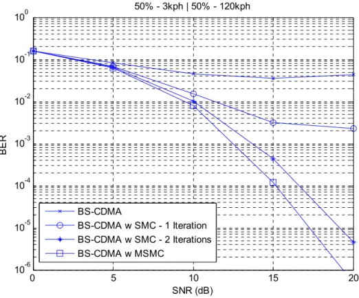
MSMC METHODS (50%-3 KM/H, 50%-60 KM/H) ...46 FIGURE 2-18 BER PERFORMANCE OF BS-CDMA USING SMC AND
MSMC METHODS (50%-3 KM/H, 50%-120 KM/H) ...47 FIGURE 3-1 TRANSCEIVER STRUCTURE OF THE TLS-CDMA SCHEME ...52 FIGURE 3-2 PACKET STRUCTURE FOR THE TWO-LAYER SPREADING
AND SCRAMBLING ...54 FIGURE 3-3 DATA STRUCTURE AFTER THE INSERTION OF CE AND
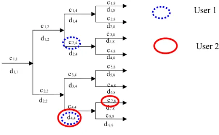
PARALLEL TO SERIAL CONVERSION ...54 FIGURE 3-4 THE PROPOSED TWO-LAYER CODE TREE STRUCTURE
CODE GENERATION FOR THE TLS-CDMA SYSTEM ...60 FIGURE 3-5 THE PROCEDURE OF DESCRAMBLING AND
DESPREADING IN TWO LAYERS ...68 FIGURE 3-6 BER PERFORMANCE OF THE TLS-CDMA SCHEME FOR A
FIXED G (QPSK) ...75 FIGURE 3-7 BER PERFORMANCE OF THE TLS-CDMA SCHEME FOR
AN ADAPTIVE G (QPSK) ...76 FIGURE 3-8 BER PERFORMANCE OF THE TLS-CDMA SCHEME (QAM) ...77 FIGURE 3-9 BER PERFORMANCE COMPARISONS AMONG THE
TLS-CDMA, CP-CDMA, MC-CDMA AND BS-CDMA
SCHEMES (V=3 KM/H) ...79 FIGURE 3-10 BER PERFORMANCE COMPARISONS AMONG
TLS-CDMA, CP-CDMA, MC-CDMA AND BS-CDMA
SCHEMES (V=60 KM/H) ...81 FIGURE 3-11 BER PERFORMANCE COMPARISONS AMONG THE
TLS-CDMA, CP-CDMA, MC-CDMA AND BS-CDMA
SCHEMES ON THE EFFECT OF DATA RATE PER USER (V=3 KM/H) ...82 FIGURE 3-12 BER PERFORMANCE COMPARISONS AMONG THE
TLS-CDMA, CP-CDMA, MC-CDMA AND BS-CDMA SCHEMES ON THE EFFECT OF DATA RATE PER USER
XII FIGURE 4-1 TRANSCEIVER STRUCTURE OF THE PROPOSED
BS-IFDMA FOR UPLINK TRANSMISSION ...87 FIGURE 4-2 BLOCK DESPREADING OF BS-IFDMA FOR NON
FREQUENCY SYNCHRONIZED CASE ...92 FIGURE 4-3 USERS SCHEDULING FOR THE BS-IFDMA SCHEME WITH
UI=4 AND UBS=2 ...98 FIGURE 4-4 SUCCESSIVE MAI CANCELLATION (SMC) FOR THE
BS-IFDMA SCHEME WITH UBS=4 ...99 FIGURE 4-5 HYBRID MAI CANCELLATION (HMC) FOR THE BS-IFDMA
SCHEME WITH UBS=8 ...101 FIGURE 4-6 THE BER PERFORMANCE OF THE BS-IFDMA SYSTEM
(V=3 KM/H) ...104 FIGURE 4-7 THE BER PERFORMANCE OF THE BS-IFDMA SYSTEM
(V=30 KM/H) ...104 FIGURE 4-8 BER PERFORMANCE FOR DIFFERENT DISTRIBUTION OF
USER MOBILITY ...106 FIGURE 4-9 PERFORMANCE COMPARISON OF INTERFERENCE
CANCELLATION METHODS ...107 FIGURE 4-10 EFFECT OF NUMBER OF ITERATIONS IN HMC METHOD ...107 FIGURE 5-1 TRANSMITTER BLOCK DIAGRAM FOR THE TCS-IFDMA
SCHEME ... 113 FIGURE 5-2 RECEIVER BLOCK DIAGRAM FOR THE TCS-IFDMA
SCHEME ... 117 FIGURE 5-3 DETAILS OF TIME DOMAIN DESPREADING PROCEDURE ... 117 FIGURE 5-4 THE BER PERFORMANCE OF THE TCS-IFDMA SCHEME
(G=2, V=3 KM/H, QPSK) ...124 FIGURE 5-5 THE BER PERFORMANCE COMPARISON AMONG
TCS-IFDMA, TLS-CDMA AND CP-CDMA (V=3 KM/H) ...125 FIGURE 5-6 THE BER PERFORMANCE COMPARISON AMONG
TCS-IFDMA, TLS-CDMA AND CP-CDMA (V=60 KM/H) ...126 FIGURE 5-7 THE BER PERFORMANCE COMPARISON AMONG
TCS-IFDMA, TLS-CDMA AND CP-CDMA (V=120 KM/H) ...127 FIGURE 6-1 UWB SPECTRAL MASK FOR US (FCC) INDOOR
XIII FIGURE 6-2 SPECTRUM OF UWB AND EXISTING NARROWBAND
SYSTEMS ...132 FIGURE 6-3 UWB SPECTRAL MASK FOR WORLDWIDE INDOOR
COMMUNICATIONS SYSTEMS ...133 FIGURE 6-4 UWB TRANSMISSION APPROACHES: SINGLE BAND AND
MULTI-BAND APPROACHES ...136 FIGURE 6-5 TRANSCEIVER STRUCTURE OF MULTI-BAND UWB
SYSTEM, WITH THE DETAILED STRUCTURE OF THE PROPOSED OVER-SAMPLING MULTI-CHANNEL
EQUALIZER ...141 FIGURE 6-6 TRANSMISSION MODES A, B AND C ...142 FIGURE 6-7. RAKE VS MMSE IN CM4 ...150 FIGURE 6-8 COMPARISON BETWEEN ANALYTICAL AND SIMULATED
RESULTS FOR RAKE RECEIVER IN CM4 ...150 FIGURE 6-9 COMPARISON BETWEEN ANALYTICAL AND SIMULATED
RESULTS FOR MMSE RECEIVER IN CM4 ...151 FIGURE 7-1 RELATIONSHIP AMONG THE PROPOSED SCHEMES ...157
XIV
LIST OF TABLES
TABLE 2-1 SIMULATION PARAMETERS FOR THE BS-CDMA SYSTEM ...38
TABLE 2-2 RELATION AMONG USER MOBILITY, DOPPLER SPREAD AND COHERENT TIME (FC =5GHZ) ...39
TABLE 3-1 SIMULATION PARAMETER FOR TLS-CDMA ...74
TABLE 4-1 SIMULATION PARAMETERS FOR BS-IFDMA ...102
TABLE 5-1 SIMULATION PARAMETERS FOR TCS-IFDMA ...123
TABLE 6-1 SALIENT PARAMETERS OF THE PROPOSED TRANSMISSION MODES ...162
1
1
INTRODUCTION
1.1
Overview of Air Interface for Broadband Wireless
Packet Access
Broadband wireless packet access should deliver much higher data transmission rates and provide more diverse services than current 2-3G systems. All-IP wireless architecture has emerged as the most preferred platform for broadband wireless packet access. Therefore, the design of a new air interface for broadband wireless packet access has to take into account the fact that the dominant load in the wireless channels will be high-speed and bursty in nature. The necessity to support such high-capacity bursty traffic in extremely unpredictable wireless channels has already posed great challenges to all existing air interface technologies.
Many research initiatives have been underway to investigate the multiple access technologies that could be most suitable for next generation wireless applications. Some suggested that current code-division multiple access (CDMA) technologies, all based on direct-sequence (DS) CDMA, are suited only for slow-speed continuous transmission applications such as voice services, but may not be a good choice for next generation high-speed burst-type broadband wireless packet access.
Therefore, a new wave of worldwide research is on the way for next-generation multiple access technologies, which should effectively address all the constraints and problems existing in current technologies, such as poor bandwidth efficiency, strictly interference-limited capacity and complexity in implementing fast adaptive equalizers.
2 The study of next-generation multiple access technologies involves many cutting edge research topics, such as broadband CDMA design, time-frequency adaptive equalization, interference-free CDMA architecture [1][2], orthogonal frequency-division multiplexing (OFDM) techniques and multiple-input multiple-output (MIMO) algorithms [3][4][5]. These will serve as a stimulus to accelerate technological evolution of multiple access technologies for next generation wireless applications.
Since the focus of this thesis is air interface suited for next generation broadband wireless packet access, a brief historical review of its worldwide development is given in the following.
First Generation Wireless Systems: Advanced Mobile Phone System (AMPS) and Total Access Communication System (TACS) were introduced in the USA and the UK respectively [6]. All these systems were based on analog technology and were often dubbed as the first generation (1G) cellular system. They used two separate frequency bands for duplexing of downlink (from base to mobile station) uplink (from mobile to base station) communications to carry only voice transmission. These two bands were separated by a “guard band” for the isolation between the downlink and uplink signals. Multiple-access is enabled by assigning different users with separate frequencies, and this is known as frequency-division multiple access (FDMA). As 1G system did not envision worldwide deployment, different 1G systems employed different frequency bands, and hence not interoperable.
Second Generation Wireless Systems: The Global System for Mobile
3 generation (2G) of cellular systems which were based on digital technology. There are three other major 2G standards: the North American Interim Standard 54 (IS-54) that later on improved into IS-136, the Japanese Pacific Digital Cellular (PDC) standard, and IS-95 in North America and South Korea [7]. GSM, IS-54/IS-136, and PDC used time-division multiple-access (TDMA) while IS-95 used code-division multiple-access (CDMA). The principle of TDMA is to separate the signals of different users by different time slots, i.e., multiplexing is done in the time domain. With CDMA the signals of different users are separated by different codes, whereas a common frequency band is shared by all users all the time. With 2G systems the transition from analog to digital was largely completed.
2.5G was an extension to the 2G systems, adding features such as packet-based services instead of circuit-switched services and enhanced data rates [8]. Generalized Packet Radio Service (GPRS) was a 2.5G system, which was an upgrade of GSM and IS-136. GPRS offered a maximum data rate of 115 Kbps. Another proposed 2.5G standard was Enhanced Data rates for GSM Evolution (EDGE) which was able to boost the theoretical data rate to 384 Kbps. EDGE could be even used as a pseudo-3G network as it offered significantly higher data rates with the same 2G spectrum without incurring exuberant 3G spectrum licensing costs for operators. The 2.5G upgrade of IS-95 was IS-95b which had added packed switched capabilities and offered data rates up to 115 Kbps.
Third Generation Wireless Systems: International Mobile Telecommunications-2000 (IMT-2000) was the global standard for 3G wireless communications, defined by a set of interdependent recommendations of the International Telecommunication Union
4 (ITU) [9]. 3G standards have been developed specifically to support high-speed data services (from 144 Kbps to 2 Mbps), including multimedia services such as high-speed internet, video and high quality image transmission. There were three different 3G standards in IMT-2000, namely the European and Japanese Wideband-CDMA (W-CDMA) [10], the American CDMA 2000 [11] and the Chinese Time-Division Synchronous CDMA (TD-SCDMA) [12]. All these standards were based on CDMA and operated around 2GHz. W-CDMA and CDMA2000 were frequency-division duplex (FDD) systems, while TD-SCDMA was a time-division duplex (TDD) system. In contrast with FDD, in which a pair of frequency bands is used for downlink and uplink separately, TDD uses a single frequency band for both downlink and uplink in different time slots. TDD requires a guard time instead of a guard band between downlink and uplink streams. TDD was chosen as duplexing scheme as it offered several advantages over FDD:
Firstly, with TDD a flexible and dynamic asymmetric downlink and uplink transmission can be easily achieved by simply assigning unequal numbers of slots or different lengths of slots to down- and uplink;
Secondly, TDD requires only one frequency band while FDD requires two. This makes TDD especially attractive as frequency spectrum is a scarce resource nowadays and as in some situations it is not possible to provide a guard band of sufficient size which is required for FDD;
Thirdly, in TDD, the channel reciprocity between downlink and uplink can be exploited to obtain approximate channel knowledge at the transmitter. This knowledge can be used to adapt the transmission signal prior to transmission;
5 However, TDD also exhibits some disadvantages compared to FDD,
The cell size cannot be large;
Cannot support users with very high mobility;
The world’s first 3G services based on W-CDMA technology was Freedom of Mobile multi-media Access (FOMA), launched in October 2001 in Japan. Also, in many other countries 3G systems have recently been launched or are planned to be launched in the near future.
Meanwhile, the enhanced version of 3G system, called high speed downlink packet access (HSDPA) and high speed uplink packet access (HSUPA) have been defined and deployed to increase the data rate up to 30 Mbps [13][14]. Moreover, the evolution roadmap for all these three standards has been considered respectively to further improve the system capacity [15] [16] [17].
Fourth Generation (or called Beyond 3G (B3G)) Wireless Systems
4G is defined in many different ways. However, most of the definitions are equally true. Several 4G definitions are given as follows [18]:
4G is the next generation of wireless networks that will replace 3G networks in the future;
4G is a mobile communications system that can provide a data rate of at least 100 Mbps between any two points in the world. In addition, between two points at short range, 1 Gbps will be possible;
6 multi-carrier modulation;
4G is a conceptual framework whose objective is to satisfy future requirements for universal wireless network that will provide high data rates and a seamless interface with a wireline backbone network;
In June 2003, ITU approved the Recommendation ITU-R M.164 “Framework and overall objectives of the future development of IMT-2000 and system beyond IMT-2000” [18]. This document defines ITU-R’s vision for 4G/B3G system and a basis of future ITU-R’s activities. Figure 1-1 shows ITU-R vision for 4G/B3G system. A new radio interface to support new services and applications is defined. There is a strong correlation between the ITU vision and the above listed 4G definitions. Figure 1-2 further zoom into the roadmap of 4G/B3G system according to mobility vs. peak data rate that has been shown as a small icon in Figure 1-1. It shows that 4G can support much higher data rate with higher mobility as described in 4G definition, thus creating many promising applications, such as IPTV.
7 As recognized in [18], the ITU vision for 4G/B3G systems comprises two major paths:
Integration and internetworking of existing and evolving access systems in the sense “optimally connected anywhere, anytime” on a packet based core network; Development of new wireless access systems for the terrestrial component as a complement to the enhanced IMT-2000 and other radio systems. It is envisioned that a new radio interface of future mobile and wireless communications systems will support data rates of up to approximately 100 Mbps for high mobility such as mobile access and up to approximately 1 Gbps for low mobility such as nomadic/local area wireless access;
Figure 1-2 Roadmap of 4G system
At the moment, there are many research initiatives for various technologies suitable for 4G air interface, which often include multi-carrier (MC) techniques such as OFDM and
Peak Useful Data Rate (Mb/s)
IMT-2000
Mobility
Low High
1 10 100 1000
New
Mobile
Acces
New Nomadic / Local Area Wireless Access
Enhance IMT-2000 Enhancement
.
100Mbps
4G/B3G
8 related schemes like orthogonal frequency-division multiple-access (OFDMA) and combinations of OFDM with CDMA, e.g., multi-carrier code-division multiple-access (MC-CDMA), multi-carrier direct-sequence code-division multiple-access (MC-DS-CDMA), and spread-spectrum multi-carrier multiple-access (SS-MC-CDMA) [20]-[23]. In the following several 4G initiatives are summarized.
WWRF Initiative: In early 2001 a consortium of partners led by Alcatel, Ericsson, Motorola, Nokia and Siemens founded the World Wireless Research Forum (WWRF) [24] [25]. This forum was focused on:
Formulation of a consistent vision of future wireless communications;
Generation, identification, and promotion of research areas and technical trends for mobile and wireless technologies;
Contribution to the definition of research programs;
Facilitation of future 4G standardization by harmonizing different views;
NTT DoCoMo Initiative: In Japan, NTT DoCoMo has been conducting 4G research since 1998. NTT DoCoMo carried out some of the first 4G field tests in the world in October 2002. Data rates of 100 Mbps in downlink and 20 Mbps in uplink were achieved. In more recent field tests conducted in 2004 a maximum downstream data rate of even 1Gbps with 100MHz bandwidth in the downlink was demonstrated. A forecast of NTT DoCoMo is that the data rates offered by 4G systems will be 100 times higher than that of 3G systems.
The air-interface proposal of NTT DoCoMo is a FDD system based on a flexible realization of MC-CDMA in the downlink, termed variable spreading factor orthogonal
9 frequency-and code division multiplexing (VSF-OFCDM), and on VSCRF-CDMA in the uplink [26] [27].
4MORE Project: In Europe, within the Information Society Technologies (IST) programme, the MC-CDMA Transmission Techniques for Integrated Broadband Cellular System (MA-TRICE) project dealt with the definition and validation of access and transmission concepts based on MC-CDMA technology for the air interface component of 4G systems. The MA-TRICE project was followed by a 4G MC-CDMA Multiple Antenna System on Chip for Radio Enhancements (4MORE) project which was another IST project conducted by almost the same consortium of partners. The objective of this project was to use the experiences of MA-TRICE and other relevant project, e.g., the NTT DoCoMo initiative, and to advance one step further towards implementation by designing a system on chip for a 4G terminal [28]. The 4MORE air interface was based on MC-CDMA in downlink and SS-MC-MA in uplink [29]. In contrast to the NTT DoCoMo initiative, a TDD system was considered. QPSK, 8-PSK, 16-QAM, or 64-QAM was used for symbol mapping while the maximum data rate in both downlink and uplink is around 100 Mbps.
WINNER project: The key objective of the Wireless World Initiative New Radio (WINNER) project, which was also an IST project, was to develop a new concept in radio access [30]. A starting premise was that the further development of non-compatible wireless systems for different purposes is not an appropriate solution for future wireless communications. Like in many other areas more global solutions and a much larger degree of convergence are expected in the future. Thus, the system realized within the WINNER project will be a ubiquitous radio concept.
10 As many individual components of the radio interfaces, such as multiple antenna techniques, multiple-access, coding, or automatic repeat request are nowadays mostly well-understood, in WINNER, a special emphasis was put on their interaction and successful combination. Several key technologies like transmission scheme, duplex scheme, adaptive transmission, multi antenna concepts, and enhanced radio protocols, as well as several scenarios like wide area, hot spot, and short range were defined. One of the main goals of WINNER was to find out which combination of key technologies is suitable for each of the scenarios.
Besides exploring technologies for the conventional band-limited system, recently many efforts have been investigated to evaluate schemes for ultra-wide spectrum. Ultra-wideband (UWB) is an emerging technology that offers great promise to satisfy the growing demand for low cost and high-speed digital wireless home networks [31]. The enormous bandwidth available, the potential for high data rates up to Gbps, as well as the potential for small size and low processing power along with low implementation cost, all present a unique opportunity for UWB to become a widely adopted radio solution for future wireless access technology [32]. Nevertheless, in order for UWB devices to coexist with other existing wireless technology, the transmitted power level of UWB is strictly limited by the Federal Communication Commission (FCC) spectral mask. Such limitation poses significant design challenges to any UWB system.
1.2
Organization of Thesis and Contributions
11 potential candidates for 4G downlink air interface. We started our research works on the enhancements of such multi-carrier scheme including a chip level interleaving (CLI) scheme [33]-[36]. Motivated by the CLI scheme for MC-CDMA, a new concept of using block spread (BS) to deal with multi-user interference for high speed transmission has been proposed. This achieves near single user performance without using MUD techniques because the code orthogonality of BS is easily maintained when the channel variation across the consecutive blocks is negligible. Subsequently, we propose a few new air interfaces for future broadband wireless packet access. The rest of the thesis is organized as follows: Chapter 2 proposes a block spread CDMA (BS-CDMA) scheme to combat MAI, giving rise to a significantly improved multi-user performance over the conventional DS-CDMA scheme in a broadband wireless channel. Chapter 3 extends the concept to a two-layer spreading CDMA (TLS-CDMA) scheme to tackle other cell interference (OCI) and achieve a lower data rate for higher-quality transmission in a multi-cell system. In addition, the BS concept proposed can be viewed as providing an additional domain for multi-user allocation. In Chapter 4, a block spread interleaved frequency division multiple access (BS-IFDMA) scheme has been formulated to use this additional domain to allocate users on top of the IFDMA domain. Furthermore, Chapter 5 proposes a two-dimensional code spreading interleaved frequency division multiple access (TCS-IFDMA) scheme to combat MAI and OCI more efficiently, enhancing DoCoMo’s variable spreading and chip repetition factor CDMA (VSCRF-CDMA) scheme. In Chapter 6, our research work has also been extended to the investigation of new air interface over ultra-wideband (>500 MHz). A multi-band UWB system
12 with over-sampling multi-channel equalization has been proposed to explore the unique property of ultra-wide spectrum to achieve ultra-high data rate like Gbps within short distance (<10 m) at low complexity and power consumption. Finally, Chapter 7 concludes the thesis and highlights the future research works.
The main contribution of this thesis is that a new concept of using BS is proposed to deal with multi-user interference for high speed transmission. This opens up an area for investigation of new air interface for future broadband wireless packet access. A few new schemes, such as BS-CDMA, TLS-CDMA, BS-IFDMA and TCS-IFDMA have been proposed and their superior performance have been shown over the existing DS-CDMA, CP-CDMA, IFDMA and VSCRF-CDMA schemes through analytical and simulation results. As such, they can be considered as promising candidates for future broadband wireless packet access in different environments. Furthermore, a new air interface over ultra-wideband spectrum has also been investigated to deliver ultra-high data rate within short range for future integration with broadband wireless packet access.
With the framework conducted in this thesis, four journal papers, ten conference papers have been published and five patents have been filed. In addition, two journal papers have been submitted for 1st revision and another two journal papers are under preparation including one journal paper for the joint work with DoCoMo. Future research topics listed in Chapter 7 will be continuously worked out.
13
2
BLOCK SPREAD CDMA
2.1
Introduction
DS-CDMA, is one of the effective wireless access technologies for supporting variable and high data rate transmission, thus it has been adopted in the 3rd generation wireless communications systems [1] [2]. However, the conventional DS-CDMA systems are affected by multipath interference (MPI) and multiple access interference (MAI), which limit the system capacity and the maximum data rate that can be supported for available bandwidth. There are two kinds of receivers for a DS-CDMA system: RAKE receiver and time-domain equalization (TDE) receiver. The performance of the receivers depends on the property of the wireless channel, as well as the traffic load. Specifically, a RAKE receiver is effective in suppressing both MPI and MAI when the spreading factor is large enough; however, this interference suppression capability will decrease with the increase of the traffic load. A TDE receiver is in theory capable of suppressing both MPI and MAI, thus restoring the orthogonality of the codes [37]. However, considering the complexity constraint and slow convergence of any practical adaptive equalization algorithms, the achievable performance usually is far below the theoretically predicted one.
Single carrier cyclic prefix assisted CDMA (CP-CDMA), an advanced version of DS-CDMA, has been proposed for broadband cellular system [38] [39]. As a block-by-block transmission scheme, CP-CDMA inserts a CP portion prior to the transmission of each data block. Though the insertion of CP slightly degrades the spectrum efficiency, it alleviates inter-block interference if the CP length is larger than
14 the channel length. More significantly, it transforms the linear convolution into circular convolution, so that FFT-based linear equalizers can be designed to recover the transmitted symbols for each user. However, it still suffers from MAI, especially when all users are asynchronous in an uplink transmission. A serial type of multistage interference cancellation in frequency domain to cancel MAI has been investigated for CP-CDMA with considerable computational complexity [40].
An alternative to CP-CDMA is multi-carrier CDMA (MC-CDMA), which combines DS-CDMA with OFDM. Different from a single carrier CP-CDMA system, that transmits the data block directly, a MC-CDMA system transmits the IFFT version of the data block. Due to the addition of CP, FFT-based low-complexity linear receivers can also be applied for MC-CDMA systems. Furthermore, through transmitting the chips signals belonging to the same symbol via multiple possibly disjointed subcarriers, MC-CDMA achieves the frequency diversity inherent with broadband wireless channels [21]. Orthogonal frequency division multiple access (OFDMA), also referred to as multiuser-OFDM, is an alternate scheme to provide user orthogonality in frequency domain [20] [41]. This is different from MC-CDMA where the user orthogonality is achieved in code domain. However, all multi-carrier schemes suffer from high peak-to-average power ratio (PAPR) and high sensitivity to frequency offset and RF phase noise. These two issues limit the applicability of multi-carrier schemes in an uplink transmission.
For frequency selective channels, CP-CDMA suffers from both MAI and MPI, and MC-CDMA systems suffer from MAI, and the interferences become very strong when the traffic is heavy. In order to combat MAI effectively over a frequency selective
15 fading channel, several methods have been proposed to improve DS-CDMA. Chip interleaving for DS-CDMA system is one of the examples where spreading and interleaving are combined for joint estimation of propagation channel gains associated with multiple users [42] [43]. Recently, Zhou et al. [44] [45] further elaborated this concept and discovered that chip interleaving is capable of combating MAI over the frequency selective fading channel for a downlink transmission.
2.2
Block Spread
Motivated by the CLI scheme as described in [33], a new concept of using block spread (BS) is proposed in this chapter to deal with multi-user interference for high speed transmission. BS is a form of spreading, in which G chips are placed over the consecutive blocks. The code orthogonality of BS is easily maintained due to the negligible channel variations across the consecutive blocks. This is because the consecutive block duration within a packet for high speed transmission is smaller than the coherence time of the wireless channel.
Figure 2-1 shows the packet structure for high speed system, where the optimum packet length is around 0.5 ms according to the analysis of NTT DoCoMo in [27] [46] because it is mainly determined by the two main factors. From the viewpoint of realizing short round trip delay (RTD) in hybrid Automatic Repeat reQuest (ARQ), which are supposed to be used to achieve high-quality packet transmission, it is desirable to design a shorter packet length.
16
CP s11 … s1M ..… CP sN1 … sNM
Figure 2-1 Packet structure for high speed system
Meanwhile, in order to derive effectually coding gain, e.g. turbo coding gain, it is reported that more than 1000 bits are needed due to the turbo interleaver size. Thus, a short packet length such as 0.5 ms is near optimum. As such, the data block duration for high speed transmission is typically a few microseconds (µs).
Figure 2-2 shows the transfer function of a broadband wireless channel in the frequency and time domains. The coherence time of a typical mobile fading channel with Doppler spread of 200 Hz is around 0.9 ms (coherence time=9 (16πfd), where
d
f is the Doppler spread) [47]. As such, the code orthogonality of BS across the consecutive blocks is easily maintained because the coherence time is much larger than the data block duration (typically a few microseconds) for high speed transmission. Comparatively, it is different from the concept of the spreading in the conventional DS-CDMA system where G chips are placed in adjacent chips. The multipath fading channel easily destroys the code orthogonality.
Furthermore, it is also different from the concept of the frequency domain spreading in the conventional MC-CDMA system where G chips of the same symbol are placed in adjacent subcarriers. The varying channel responses among subcarriers due to the frequency selective fading channel destroy the code orthogonality of the frequency domain spreading across the adjacent subcarriers. This analysis concludes the
Frame (0.5ms)
17 superiority of the BS over the spreading in the conventional DS-CDMA system and the frequency domain spreading in the conventional MC-CDMA system to in MAI removal.
Figure 2-2 Transfer function of broadband wireless channel
2.3
Block Spread CDMA (BS-CDMA)
In an uplink transmission, since the signals from different users go through different propagation channels, the performance degrades significantly due to the strong MAI in DS-CDMA, CP-CDMA and MC-CDMA. Multi-user detection (MUD) has to be used to suppress MAI and thereby improve the uplink performance. In this chapter, by using the concept of BS, a block-spreading CDMA (BS-CDMA) scheme is proposed to improve uplink performance over broadband wireless channel. Instead of introducing a chip interleaving for DS-CDMA as described in [42]-[45], we propose a block-by block transmission using BS for CDMA system to combat MAI effectively over a time invariant channel. In addition, we propose a symbol-wise frequency domain process with despreading before equalization, saving power significantly. We
18 also propose a cell-specific scrambling code to suppress other-cell interference (OCI) effectively for uplink transmission in a multi-cell system. By adding cyclic extension (CE) instead of CP, it is capable of handling multi-user asynchronous uplink transmission.
2.3.1
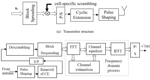
The Transmitter Structure
We show the transmitter structure and receiver structure of block diagram of the proposed BS-CDMA system in Figure 2-3 (a) and (b) respectively. The block spreading and cell-specific scrambling blocks are the new blocks which are different from the conventional DS-CDMA at transmitter. In addition, the symbol-wise frequency domain process with despreading before equalization is also different from the conventional DS-CDMA at receiver, leading to power saving. Figure 2-4 shows the input and output data structure of block spreading and scrambling module. Let the column vector
T M i i i
i =[s,1,s,2,...,s, ]
s denote a block of M modulated data symbols for user i, where U
i≤
≤
1 . The block spreading is performed by repeating the data block for user 1 by G times, with each block denoted by s1[b], where 1≤b≤G. Let the column vector
T G i i i
i =[c,1,c,2,...,c, ]
c denote the spreading code vector for user i, where 1≤i≤Uand G is the spreading factor. The cross-correlation of the spreading code among different users is T j =0
ic
c for i≠ j; Let the column vector L=[L1,L2,...,LG]Tdenote the cell-specific scrambling code in an uplink transmission, with the same period of G as the spreading code. Figure 2-5 shows the data structure after parallel-to-serial (P/S) conversion. Subsequently Figure 2-6 shows the data structure after insertion of CE, with a fixed number of tail chips are prefixed to the beginning of the block (cyclic
19 prefix, referred to as CE1a) and a fixed number of header chips are appended at the end of each block (cyclic postfix, referred to as CE1b). By adding CE instead of CP, the scheme is capable of achieving multi-user asynchronous uplink transmission. Figure 2-7 shows the illustration of CE handling multi-user asynchronous uplink transmission (three users), keeping a perfect orthogonality among received signals irrespective of the late / early arrival of the received signal among different users [48]. After block spreading and scrambling, the mth data symbol of the bth block for the uth user can be described as:
b b u m u m
u b s c L
d , [ ]= , ⋅ , ⋅ (2.1)
where su,m is the mth symbol of the block for the uth user and 1≤m≤M , cu,b is the block spreading code of the bth block for the uth user, where 1≤b≤G and Lb is the
(a) Transmitter structure
(b) Receiver structure
Figure 2-3 Block diagram of the proposed BS-CDMA system
(a)
Cyclic Extension
Pulse Shaping
Block
Spreading P/S
cell-specific scrambling
20
s11 s12 … s1M s11 s11c11L1 s11c12L2 … s11c1GLG s12 s12c11L1 s12c12L2 … s12c1GLG
… … … … …
s1M s1Mc11L1 s1Mc12L2 … s1Mc1GLG
Figure 2-4 Input and output data structure of block spreading and scrambling module
s11c11L1 … s1Mc11L1 ..… s11c1GLG … s1Mc1GLG Figure 2-5 The data structure after parallel-to-serial conversion
CE1a s11c11L1 … s1Mc11L1 CE1b ..… CEGaS12c1GLG … s1Mc1GLG CEGb
Figure 2-6 The data structure after insertion of CE (CE1a is cyclic prefix and CE1b is cyclic
postfix of block 1)
Figure 2-7 The illustration of CE handling multi-user asynchronous uplink transmission (three users)
Block of data
Combined signal at the receiver
user1
user 2 (late arrival)
(early arrival)
Block 1 Block G
Modulated data After S/P After block spreading and scrambling
Block 1 Block G
Block 1 Block G
Copy Cyclic Prefix
Cyclic Postfix Copy
21 cell-specific scrambling code of the bth block.The proposed BS-CDMA system adds a cyclic prefix of Q1chips at the beginning and a cyclic postfix of Q2chips at the tail for each block. The resulting expression for the transmitted waveform is as follows:
) )) 1 ( ) ( ) 1 (( ( ] [ )
( 1 2
1 , 2 1 c b Q Q M m m u
u t x b t b M Q Q m T
x =
∑
∑
⋅Ω − − ⋅ + + + − ⋅∞ −∞ = + + = (2.2)
where Tc is the chip spacing and
⎪ ⎩ ⎪ ⎨ ⎧ + + ≤ ≤ + + + ≤ ≤ + ≤ ≤ = − − − − + 2 1 1 , 1 1 ) ( , 1 ) ( , , 1 ] [ 1 ] [ 1 ] [ ] [ 1 1 1 Q Q M m Q M b d Q M m Q b d Q m b d b x Q M m u Q m u Q M m u m u
where Ω
( )
t is the rectangular function. If Q1 and Q2 are set to be 0, xu,m[b] is equal to du,m[b] for 1≤m≤M and 1≤b≤G.In an uplink transmission, the signal from each user passes through a different multipath channel which is characterized as follows:
∑
= − = P p p u uu t p t
h 1 , ) ( ) ( )
( α δ τ
(
(2.3)
where P is the number of paths, αu(p) is the instantaneous complex path gain of the
pth-path for the uth user, τu,p is the time delay of the pth-path for the uth user and δ(t)is the Dirac delta function.
2.3.2
The Receiver Structure
For an uplink, the base station receives the data streams from all users asynchronously, having undergone different propagation conditions. The received data passes through
22 the matched filter, the removal of CE, the block descrambling and despreading block before transforming into the frequency domain through the FFT block. The FFT and FDE are all in symbol-wise operation after block despreading, which leads to a simpler receiver structure than the chip-wise operation of CP-CDMA system as described in [38], with considerable power saving.
Assuming that there are U active users, the received signal r(t)at the base station can be expressed as:
) ( ) ( ) ( )
(
1
t n t h t x t
r
U
u
u
u ∗ +
=
∑
=
(2.4)
where n(t) denotes Additive White Gaussian Noise (AWGN) and ∗ denotes convolution operation, hu(t) is the combined impulse response of the transmit chip pulse shaping filter pt(t) (assumed to be square-root raised cosine) and the frequency selective fading channel response h(u(t) and the receive match filter pr(t):
) ( ) ( ) ( )
(t p t h t p t
hu = t ∗(u ∗ r (2.5)
The BS-CDMA receiver performs chip-rate sampling after the matched filtering. The respective cyclic prefix of Q1 chips and the postfix of Q2 chips are discarded in each block. Let rm[b] denote the remaining M chip samples corresponding to the mth symbol of the bth block:
[ ]
b s c L h[ ]
b[ ]
br m
U u
p u b P
p
b u p m u
m =
∑ ∑
⋅ ⋅ ⋅ +η= =1 1 ,( − ) , ,
(2.6)
23
[ ]
bm
η represents the AWGN component at sample m of the bth received block and ]
[
, b
hu p denotes the pth path of the channel of the uth user for the bth received block. For our derivation, perfect synchronization among users has been assumed. However, in the illustration in the next section, we have considered both chip-synchronized and non chip-synchronized cases for the proposed BS-CDMA.
2.3.3
The Block Descrambling and Despreading
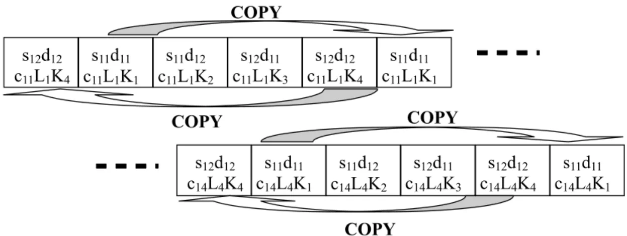
Figure 2-8 illustrates the detailed procedure of block descrambling and despreading, assuming the presence of a desired User 1 (U1) and an interfering User 2 (U2). Assume that user 1 has two multipaths denoted in the figure as U1P1, U1P2 with respective channel responses h11, h12. User 2 has only one multipath (U2P1) with channel response h21. The block length M and the spreading factor G are all set to be 4 for simple illustration. Figure 2-8 (a) shows a chip-synchronized case where the arrival time difference among users is less than the length of the cyclic prefix and cyclic postfix. User 1 and user 2 arrive at base station at a different time of multiple chips and they are synchronized in chip level. In the illustrated example, one chip difference is assumed. By using the CE, we cover the early / late signal arrival among multiple users without introducing any inter-block interference within an individual block windowing. The descrambling and despreading are implemented block by block by multiplying the product of the respective spreading code and cell-specific scrambling code in each block windowing. Chip sequences are then re-ordered in such a way that the different chips of the same symbol are grouped together for the descrambling and despreading. For instance, the four chips of Sym #1 for the first multipath of user 1 (U1P1) is grouped
24 into s12c11L1, s12c12L2, s12c13L3, s12c14L4. We note that Sym #1 may not be the first symbol of each user, such as s11 or s21 because of multipaths. In this example, Sym #1 for the first multipath of user 1 (U1P1) is the second symbol s12 and Sym #1 for the first multipath of user 2 (U2P1) is the first symbol s21. Similarly, Sym #1 for the second multipath of user1 (U1P2) is the first symbol s11. It is observed that the arrival time difference among users does not destroy the code orthogonality of the block spreading because the symbol, e.g. s21, is a common part for the MAI from users during the despreading. Hence, the MAI term from user 2 is completely removed when L2b is a constant. However, it is noted that the MPI term due to the multipath is still remained. That is to say the proposed BS-CDMA system is only robust against MAI, but requires an equalizer, e.g. frequency domain equalizer, to equalize the MPI effect. Similar to Figure 2-8 (a), it is shown in Figure 2-8 (b) that the arrival time difference is the same as the length of the cyclic prefix and cyclic postfix for a chip-synchronized case. It is seen from the black box of block 1 windowing that the MAI from user 2 can also be completely removed. However, it is shown in Figure 2-8 (c) that the MAI from user 2 cannot be completely removed due to the inter-chip interference when the arrival time difference is beyond the length of cyclic prefix and cyclic postfix for a chip-synchronized case. In such a case, an adaptive transmission timing control using reservation packet is able to ensure the arrival timing difference is within the cyclic prefix and cyclic postfix [52]. In summary, for a chip-synchronized case, as long as the arriving time difference is within the length of the cyclic prefix and cyclic postfix, the code orthogonality of the block spreading for CDMA is maintained.
25 arriving time difference is within the length of the cyclic prefix and cyclic postfix. User 1 and user 2 arrive at basestation at a different time which is not an integer number of chips. Specifically, the chip sequences from user 2 are not synchronized with the chip sequences from user 1 in chip level. After the re-ordering of chip sequences in such a way that the different chips of the same symbol are grouped, it is seen that the chips from two partial symbols from user 2 are in the same chip duration as one symbol from user 1. For example, in the first chip duration of Sym #1, due to the non chip-synchronization, the chip s11c11L1 (first multipath) from user 1 is added together with a mixed chip (s24c21L1 and s21c21L1) consisting of two partial symbols s24 and s21 from user 2. After the descrambling and despreading, the MAI from user 2 is completely removed because there is a common part of the two partial symbols s24 and s21 for the MAI term from user 2 during the despreading. That is to say the arrival time difference among users which is not chip-synchronized does not destroy the code orthgonality of the block spreading as well.
26 (a) Chip-synchronized case (the arrival time difference is less than the length of cyclic prefix and
cyclic postfix)
(b) Chip-synchronized case (the arrival time difference is same as the length of cyclic prefix and cyclic postfix)
(c) Chip-synchronized case (the arrival time difference is beyond the length of cyclic prefix and cyclic postfix)
(d) Non chip-synchronized case (the arrival time difference is within the length of cyclic prefix and cyclic postfix)
27 Specifically, after the block descrambling and despreading, the mth data symbol sˆi,m for the ith user can be described as follows:
[ ]
∑
= ⋅ ⋅ = G b b b i m mi r b c L
s 1 , , ˆ
[ ]
∑
∑ ∑ ∑
= = = = − ⋅ ⋅ + ⋅ ⋅ ⋅ ⋅ ⋅ = G b b b i m b b i G b U u p u P p b b u p mu c L h b c L b c L
s
1 ,
,
1 1 1 ,( ) , ,
] [
η (2.7)
Assuming that the channel variation across the consecutive blocks is negligible, we can replace hu,p
[ ]
b with hu,p. Therefore, (2.7) can be rewritten as follows:m b P p U i u u G b b i b u p u p m u P p b G b p i p m i m
i s h c L s h c c L
s b i η ′ + ⋅ ⋅ ⋅ + ⋅ ⋅ ⋅ =
∑
∑
∑ ∑
∑
= ≠ = − = = − = 2 1 1 ,( ) , 1 , , 1 2 1 2 , ) ( , , , ˆ (2.8)where
∑
= ⋅ ⋅ = ′ G b b b i m
m b c L
1 ,
] [
η
η represents the AWGN component which has the
same variance of σn2 as ηm in (2.6).
If L2b is a constant, (2.8) can be further simplified into:
m P p p i p m i m
i s h
s =
∑
⋅ +η′=1 ,( − ) , ,
ˆ (2.9)
It is seen from (2.9) that MAI is completely removed over an time invariant channel without any complex multi-user detection technique.
After the block descrambling and despreading, it is noted that the proposed BS-CDMA system has become a conventional single carrier system with CP. A one tap equalizer
28 can be used to equalize the mulitpath effects with low complexity [49] [50]. Due to the despreading before equalization, frequency domain process becomes symbol-wise operations. This is different from CP-CDMA and MC-CDMA. As a result, the power consumption of the frequency domain process can be reduced by a factor of G.
The weight W1 of a single tap equalizer is estimated with the help of the pilot symbols.
Both Zero Forcing (ZF) and Minimum Mean Squared Error (MMSE) are considered. In the frequency domain, (2.9) can be rewritten as follows:
] [ ] [ ] [ ] [
ˆ k H k S k N k
Si = i ⋅ i + (2.10)
where Sˆi[k], Si[k], Hi[k]and N[k] are the corresponding frequency domain functions of the respective sˆi,m , si,m , hi and η'm as defined in (2.9), e.g.
∑
= − − − ⋅ = M m M m k j m ii k s e
S 1 / ) 1 )( 1 ( 2 , ]
[ π and
∑
= − − − ⋅ = P p P p k j p i
i k h e
H 1 / ) 1 )( 1 ( 2 , ]
[ π .
The linear frequency domain equalization can be employed on each frequency bin as follows: ] [ ˆ ] [ ]
[k W k S k
Zi = i ⋅ i (2.11)
where the set of weights {Wi[k];k =1,2,LM}for the ith user can be chosen based on ZF and MMSE [51][52].
Under the ZF criterion, the weight Wi[k]is given:
] [ ˆ ] [ ˆ ] [ ˆ ] [ * * k H k H k H k W i i i i ⋅
29 which leads to an inter-symbol interference (ISI) free situation at the equalizer output if
] [ ] [
ˆ k H k Hi = i .
Under the MMSE criterion, the weight Wi[k] gives better compromise between ISI
and Gaussian noise:
2 2 * * / ] [ ˆ ] [ ˆ ] [ ˆ ] [ s n i i i i k H k H k H k W σ σ + ⋅
= (2.13)
where σn2 is the variance of η'm and 2
s
σ is the variance of si,m.
After the equalization, the data {Zi[k];k =1,2,...,N} is transformed into time domain signal }{zi[n];n=1,2,...,N as follows:
∑
= − − ⋅ = M k M n k j i Mi n Z k e
z 1 / ) 1 )( 1 ( 2
1 [ ]
]
[ π (2.14)
Substitution of (2.10) and (2.11) into (2.14), zi[n] can be rewritten as:
∑
∑
∑
≠ = − − = = ⋅ ⋅ ⋅ + ⋅ ⋅ = M n m m M m n k j m i M k i i M n i M k i i Mi n W k H k s W k H k s e
z 1 / ) )( 1 ( 2 , 1 1 , 1
1 [ ] [ ] [ ] [ ]
] [ π M n k j M k i
M W k N k e
/ ) 1 )( 1 ( 2 1
1 [ ] [ ] − −
=
⋅ ⋅
+
∑
π (2.15)In (2.15), the first term represents the desired signal component, the second term is ISI owing to MPI (μISI) and the third term is the noise component (μnoise). The time domain signal can be detected using standard methods. The pilot symbols are periodically inserted within each block spreading module for channel estimation. The
30 required frequency of the pilot symbol insertion depends on the velocity of temporal variation of the channel. Any common channel estimation method can be applied for the proposed BS-CDMA system. Perfect synchronization is assumed at the receiver.
2.3.4
Performance Analysis
In this section, we shall derive the average bit error rate (BER) based on Gaussian approximation of ISI and the analytical BER lower bound and then, BER performance is numerically evaluated.
Theoretical Average BER
From (2.15), it is known that the ISI can be approximated as a zero-mean complex-valued Gaussian noise. The sum of the second and third terms of (2.15) can be treated as a new zero-mean complex-valued Gaussian noise. The variance of each term is as follows:
⎥ ⎥ ⎦ ⎤ ⎢ ⎢ ⎣ ⎡ ⋅ − ⋅ = =
∑
∑
= = 2 1 i 1 2 1 i 1 2 2 2 12 [| | ] 2 W[ ] [ ] M W[ ] [ ]
k i M M k i M ISI
ISI E k H k k H k
s
σ
μ
σ (2.16)
2 1 i 1 2 2 2 1
2 [| | ] 2
∑
W[ ]= = = M k M noise
noise E k
n
σ
μ
σ (2.17)
We assume quaternary phase shift keying (QPSK) modulation. The conditional BER for the given set of {Hi[k]and }Wi[k];k =1,2,...,N can be expressed as [47] [54]:
(
)
⎥⎦⎤ ⎢⎣ ⎡ = , [ ] ]) [ ,(SNR H k 12erfc 14 SNR H k
31
where =
∫
∞ −x t dt
x
erfc[ ] (2/ π) exp( 2) is the complementary error function and
(
SNR,Hi[k])
γ is the conditional signal to interference and noise ratio (SINR) defined as:
(
)
(
2 2)
2
1 i 1
2 W[ ] [ ]
] [
, M ISI noise
k
i M
s
i k k H k
H
SNR σ σ σ
γ = ⋅
∑
⋅ += ⎥ ⎥ ⎦ ⎤ ⎢ ⎢ ⎣ ⎡ ∑ + ∑ ⋅ − ∑ ⋅ ⋅ ∑ ⋅ ⋅ = = = = = 2 1 i 1 2 1 i 1 2 1 i 1 2 1 i 1 ] [ W ] [ ] [ W ] [ ] [ W ] [ ] [ W 2 M k M M k i M M k i M M k i M k k H k k H k SNR k H k SNR (2.19)
where SNR=σs2/σn2. The theoretical average BER Pb(SNR) can be numerically evaluated by averaging (2.19) over {Hi[k];k =1,2,...,N}
(
) (
)
∏
∫ ∫
⎢⎣⎡ ⎥⎦⎤ = k i i ib SNR erfc SNR H k p H k dH k
P ( ) , [ ] { [ ] [ ]
4 1 2
1 γ
L (2.20)
where p
(
{Hi[k])
is the joint probability density function (PDF) of {Hi[k];k =1,2,...,N}.BER Lower Bound
It can be observed from (2.16) (2.17) and (2.19) that γ
(
SNR,{
Hi[k]}
)
achieves a maximum value as the effect of ICI is cancelled. Thus,{
}
(
)
∑
∑
= = = M k i M M k i i M i k W k H k W SNR k H SNR 1 2 1 2 1 1 max ] [ ] [ ] [ 2 ] [ ,32
When ][ ] *[
k H k
Wi = i or with maximum ratio combining (MRC) equalization, (2.21) can be further simplified to become
{
}
(
)
∑
= = M k i Mi k SNR H k
H SNR
1
2 1
max , [ ] 2 [ ]
γ (2.22)
An equivalent expression can be obtained:
{
}
(
)
∑
= = P p p i Mi k SNR h
H SNR 1 2 , 1
max , [ ] 2
γ (2.23)
Denoting the pdf of
∑
= = P p p i h 1 2 ,β by p(β), the average BER is lower bounded by
(
)
βσσ( )
β βd p erfc SNR P n s N lower b ⎥⎦ ⎤ ⎢⎣ ⎡
=
∫
∞ 22 21 0 2
1
, (2.24)
Consider a frequency selective Rayleigh fading channel with uniform power delay profile. Then,
{ }
hi,p are zero-mean and i.i.d. complex-valued Gaussian variables with variance 1/P. The pdf of γ is therefore( )
(
P)
P P p P P β β
β = exp −
! (2.25)
Thus, the lower bounded average BER is given by
(
)
⎪⎭ ⎪ ⎬ ⎫ ⎪⎩ ⎪ ⎨ ⎧ ⎥⎦ ⎤ ⎢⎣ ⎡ ⎟ ⎠ ⎞ ⎜ ⎝ ⎛ + ⎟⎟ ⎠ ⎞ ⎜⎜ ⎝ ⎛ − + ⋅ ⎥⎦ ⎤ ⎢⎣ ⎡ ⎟ ⎠ ⎞ ⎜ ⎝ ⎛ − =∑
− = + + p Pp SNR P
SNR P P SNR SNR lower b p p P SNR P 1
0 2 2
1 2 2 1 , 1 1 1 (2.26)
where ⎟⎟
⎠ ⎞ ⎜⎜ ⎝ ⎛ y x