© Shiraz University
Finite Element Simulation of Two-Point Incremental Forming of Free-Form Parts
M. Esmailian
*and K. Khalili
Department of Mechanical Engineering, University of Birjand,P.O.B. 9717431396, Iran.
Abstract: Two-point incremental forming method is considered a modern technique for manufacturing shell parts. The presence of bottom punch during the process makes this technique far more complex than its conventional counterpart i.e. single-point incremental forming method. Thus, the numerical simulation of this method is an essential task, which leads to the reduction of trial/error costs, predicts the tearing of sheet and investigates various aspects of this complex method. Most of the previous works regarding numerical simulation of incremental forming method have concentrated on the single-point type of this technique. Moreover, all of these simulations have considered simple geometries like truncated cone, truncated hemisphere and truncated regular pyramid, which are based on well-known mathematical functions. In this study, a novel simplified procedure is presented for the finite element simulation of two-point incremental forming of free-form parts. The procedure is based on the extraction of tool-path points by using CAM software and the finite element model. In the current study, it will be shown how simulated results can be applicable for gaining useful information about the tearing of deforming sheets, selecting suitable numerical machines for practical forming processes and the deformation quality of sheets.
Keywords: Two-point incremental forming, finite element method, numerical simulation, free-form.
1. Introduction
The incremental forming process is a technique in which the sheet is formed by a spherical-head tool under a series of small incremental deformations. Studies have shown that in addition to the metal sheets, this process is applicable for the polymeric and composite sheets [1, 2]. The spherical-head tool required for this process is connected to a CNC machine or a robot arm, and has the head diameter of 5 to 20 mm. Based on the connecting points between the tools, sheet and punch, this technique is divided into SPIF (Single-Point Incremental Forming) and TPIF (Two-Point Incremental Forming). Trzepiecinski et al. [3] studied the characteristics of incremental forming of the sheet using the following two methods: Single-Point Incremental Forming and Two-Single-Point Incremental forming. Parande et al. [4] have reviewed the use of incremental sheet metal forming in order to reduce the cost of Rapid Prototyping and increase in forming limit curve against other conventional forming methods.
There are several researches about the behaviour of sheet during incremental forming process. The methods used in these studies can be generally categorized into the analysis and simulation. In analytical approach, the use of fundamental rules in deforming metals, the formability of metal sheets and the induced stresses in this process are analyzed. In 2008, by using “Membrane Analysis”, Martins et.al [3] presented a comprehensive analysis about the formability of sheet in SPIF process. In 2009, Jackson et al. [4] presented the sheet deformation mechanism in the incremental forming process. Interestingly, all of the analytical approaches have investigated the SPIF process. However, the numerical simulations have focused on the analysis of incremental forming. Mainly, the numerical method used in these analyses is FEM (Finite Element Method). The first step towards the numerical simulation of this process was taken
by Iseki et.al [5] in 1993. By analyzing the two-dimensional simplified model by using FEM, he investigated this process. The research carried out in 2009 by Silva et al. [6] can be considered the most recent one studying this field. In his investigation, the three-dimensional simulation by LS-Dyna software gives a comprehensive analysis of this process, and the shell elements are used for simulating the metal sheet deformation. Zahedi et al. [7] analyzed the forming of two-layer sheet metals in SPIF process by simulating a cone with a variable angle in ABAQUS finite element software. Jackson et al. studied an artificial neural network (ANN) based on a prediction model developed to evaluate average surface roughness (Ra) and maximum forming angle (Ømax) during SPIF forming of AA5052-H32 material.
Considering previous researches about TPIF, two points should be highlighted. First, most of the simulation-based analyses have been performed for SPIF process, and the reason is the simplicity of implementation and simulation of SPIF compared to TPIF. Among few articles using numerical simulation of TPIF, references [8, 9] can be mentioned. Second, in all presented articles, numerical simulations have been done for the definite-form and regular (symmetric) parts like the truncated cone, truncated hemisphere and truncated regular pyramid, and there is not a numerical simulation about the incremental forming of free-form parts. The main reason behind this issue is the difficulties associated with the implementation of tool-path in the simulation of free-form parts. For definite-form and regular parts, as those mentioned above, the tool-path has been easily defined and implemented in simulation by simple mathematical functions.
In this study, a facilitating workflow is presented for the simulation of TPIF on free-form parts. The simulation of this process is absolutely crucial in analysing the formability of sheet in TPIF tool forces as well as reviewing the effects of different parameters including tool radius, sheet thickness, tool step-down, optimized tool-path, etc. Since the simulation of this process requires much attention to details, a detailed workflow of finite element model of this process is presented. This workflow helps the reduction of modelling errors; and the path for future researches about analysing different parameters of TPIF is paved.
2. Two-Point Incremental Forming of FE (Finite Element) Modeling
In this section, the detailed workflow of FE modelling in TPIF has been illustrated. It should be noted that this workflow is applicable in every free-form part.
2.1. Introducing the example problem
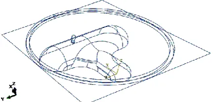
The geometry of example free-form part, regarding the FE modelling procedure, is shown in Fig. 1. The studied sheet is Aluminum 2024 in 400 × 400 mm square shape with the thickness of 1mm before the heat treatment. Except for the movement along depth direction, all freedom degrees on four sides of square sheet are considered to be zero. The movement along depth direction is controlled by a holding ring, which has only one freedom degree along depth. The radius of spherical-head tool for forming process is 10 mm. The friction coefficient between tool and sheet is assumed to be 0.1 and the tool has angular velocity of 30Rad/s along its axis [13].
2.2. General workflow of FE modeling
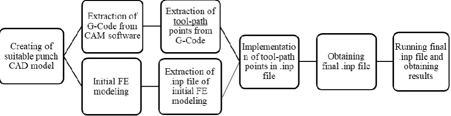
The workflow diagram and software used in FE modeling are shown in Fig. 2. Generally, the workflow of simulation can be categorized in 3 steps: 1. the extraction of tool-path points; 2. the performance of initial FE modeling without considering tool path; 3. the implementation of tool-path points in the initial FE Model. In the first step, the tool-path points need to be extracted, and for this reason, CAM software can be used. Once the G-code is extracted from the CAM software, by using a customized Excel file, the final points of tool-path can be obtained. In the second step, the initial FE modeling of TPIF should be carried out. In this study, ABAQUS finite element software is chosen for this task. In this step, FE modeling is carried out without considering tool movement during analysis. After the initial modeling is carried out, the ABAQUS ‘inp’ file of finite element model is extracted from software. Obviously, this initial ‘inp’ file lacks tool-path definition. In the third step, in order to implement the tool-path, a special MATLAB script is employed. This script reads the tool-path points from Excel file and modifies the initial ‘inp’ file, finally adding the definition of tool-path to the FE model. Hence, this script gives a final ‘inp’ file as an output that contains tool-path definition. Moreover, in this script, some parameters including mass-scaling coefficient, tool-path points distance tolerance, etc. are variable, and the user can change them if needed.
2.3. Extraction of tool-path points
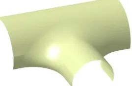
In order to extract the tool-path points, at first some modifications must be done on CAD model of the part in order to create an appropriate model. In TPIF process, sheet is gradually placed on the punch and gets its form. Therefore, the punch should have no sharp edges; otherwise, during simulation and even practical process, tearing of sheet will be inevitable. Therefore, by stretching the sharp edges, an appropriate punch CAD model for TPIF process is created. The appropriate punch CAD model of the free-form part presented in Fig. 1 is depicted in Fig. 3. Note that while the sheet formed by this punch will differ from the main piece, by cutting the additional fractions, the desirable part will be achieved. In the next step, the tool-path on punch is extracted by CAM software in which, by setting the machine type on “Mill” and the path type on “Surface finish/contour”, the tool-path on punch is obtained, as presented in Fig. 3. In the extraction of tool-path, the maximum step-down of tool is set on 1 mm. The selection of this value depends on the desirable surface quality of final product and sheet formability.
2.4. Initial FE modelling
In this stage, the initial FE modelling of TPIF process by using ABAQUS software is presented. The reason for calling this modelling as ‘initial’ is the lack of defined tool-path in this modelling. As mentioned earlier, after this initial modelling, the tool-path is added to ‘inp’ file of initial modelling by a MATLAB script.
Fig. 3. Tool-path obtained from CAM software on punch designed for part.
2.4.1. Creating parts
First, all necessary parts involved in this simulation are created. Due to their less deformation than sheet, tool, punch and holding ring, are modelled as the rigid bodies.
2.4.2. Definition and specification of material properties
Since tool, punch and holding ring are modelled as rigid bodies, there is a need to define materials for them, and only creating a reference point for determining their boundary conditions will suffice. The sheet metal used is made of Aluminum 2024. Density of this material is 2700 Kg/m3. In order to define linear elastic properties, elastic modulus and Poisson’s ratio of this material are taken to be 7000 MPa and 0.33, respectively. The diagram for changes in plastic strain against True stress for aluminium 2024 has been shown in the Fig. 4.
Fig. 4. Diagram changes plastic strain against True stress for aluminium 2024 [14].
2.4.3. Assembly of parts
The assembly of involved parts relative to each other is one of the most important steps in initial FE modelling, which should be done very carefully to prevent untimely tearing of sheet during simulation and divergence of numerical scheme. For the punch of saddle-like part, the accurate relative position is shown in Fig. 5.
2.4.4. Definition of analysis step, boundary conditions, contact and necessary sets
recognizable by MATLAB script, the name of the step must be given as “Step-1”. In addition, in MATLAB script, the boundary conditions of parts, including tool movement, are applied by using previously defined sets. Therefore, in initial FE modelling, it is necessary to define sets on reference points of tool, punch, holding ring, four edges of sheet and whole sheet and to define the name of these sets like the input parameters at the beginning of MATLAB script. The general contact algorithm is used for the contact between parts and the friction coefficient is also considered 0.1.
Fig. 5. Accurate assembly of involving parts in numerical simulation.
2.4.5. Meshing
In the next step of FE modelling, by considering the required accuracy and capabilities of processor (CPU), the meshing is carried out. Two points are important in this stage. First, the mesh size of sheet cannot be large enough to cause the stretching and excessive distortion of sheet elements. Second, in contact formulation, due to the deformability, sheet plays the role of slave, while the rigid punch plays the role of master. In contact formulation in ABASQUS, there is a possibility for passing master surface nodes through the space between slave surface nodes. To reduce this non-physical possibility, the meshing size of slave surface should be smaller than the master surface. In the current problem, regarding the mentioned points, the appropriate meshing on sheet and punch is created. For sheet, the 4-node reduced integration shell element (S4R) is used.
2.4.6. Extracting ‘inp’ file of initial FE modelling
Finally, ‘inp’ file of initial FE modelling, which lacks tool-path, is obtained from ABAQUS.
2.5. Implementation of tool-path in FE model
In order to apply the tool-path in FE model, it is necessary to appropriately implement the extracted points in Excel file into ‘inp’ file of initial FE modelling. To do so, a script is written in MATLAB language.
The general workflow used in this script is described herein. First, the extracted points in Excel file are read by MATLAB workspace. Then, if the distance between two consecutive points is more than the user-defined tolerance, one or more points should be inserted between these points so that the distance between any two consecutive points becomes less than the specified tolerance. The reason is that during the creation of points in G-code, if CAM software recognizes the path as a straight line, only the beginning and end points of that line should be printed in G-code. Hence, if the mentioned provisions are not assumed, during the simulation process, sheet will tear untimely.
In Table 1, a summarized report of significant parameters is used for FE analyses, and experiments tests are provided.
Table. 1. Significant parameters used for FE analyses and experiments test
Sheet Dimensions
Sheet Thickness
Sheet Material Tool Diameter Friction coefficient between tool and sheet
Tool Rotation Speed
Step Down
400 × 400 mm 1mm Aluminium 2024 10 mm 0.1 30Rad/s 1mm
3. Results and Discussion
In order to ensure the reliability of simulation results, they are compared with the data obtained from the experiment. The actual sample of punch created for a saddle-like part and configuration of experiment for TPIF practical process are shown in Fig. 4 and Fig. 6, respectively.
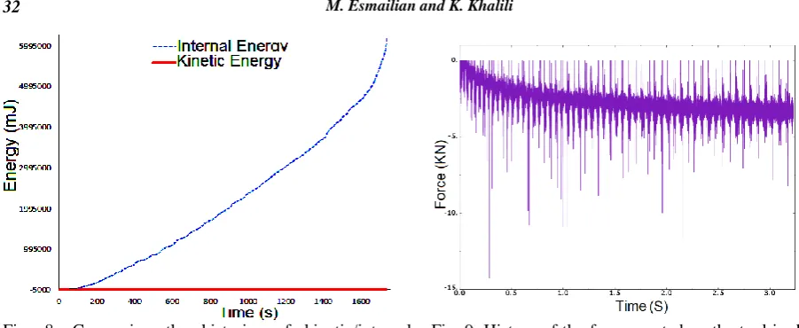
Additionally, to investigate the quasi-static nature of simulation process, the changes of kinetic/internal energies of structure are compared in the course of analysis as shown in Fig. 7. As it can be seen from the figure, in comparison to the internal energy, the kinetic energy of the model is dispensable and the simulation has a quasi-static nature.
Fig. 6. Actual punch created for saddle-like part. Fig. 7. Configuration of experiment of TPIF for saddle-like part.
One of the results obtained from simulation which can help the practical process is the calculated value of the force exerted on the tool. The understanding from the force exerted on the tool provides the user with a good criterion for choosing the appropriate CNC machine to carry out the practical incremental forming process. The force exerted on the tool on depth direction during the simulation is depicted in Fig. 8. If the sudden changes in the diagram are overlooked, the maximum value of the force exerted on the tool during the forming process equals 3KN.
The equivalent plastic strain contours of deformed sheet, when the tool is passing down to 10, 20, 30, 40mm, are demonstrated in Fig. 9. In fact, in points where the plastic strain is higher, the sheet tearing becomes more possible. In order to determine the possibility of sheet tearing, one should compare the main strains in each point with the forming limit diagram FLD (Forming Limit Diagram) of sheet.
Fig. 8. Comparing the histories of kinetic/internal energies during the course of TPIF simulation.
Fig. 9. History of the force exerted on the tool in depth direction obtained from simulation.
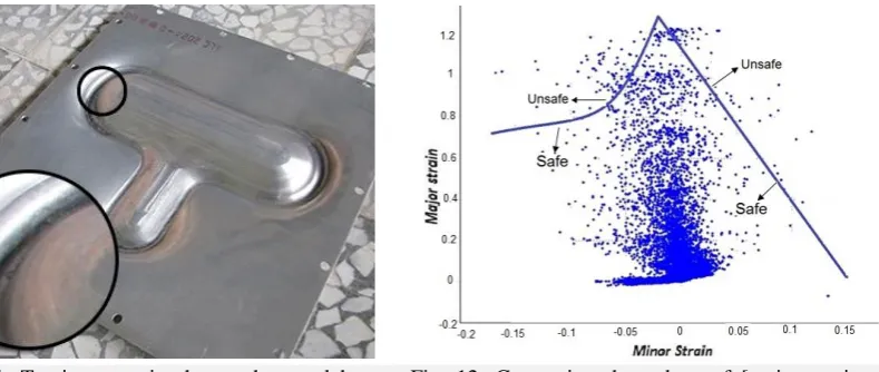
In practical process, the formed sheet, when the tool comes down by 34 mm from the initial location, is shown in Fig. 10. As shown in this figure, the sheet tearing is observed for the first time at this location of the tool. However, this issue is predictable with the help of simulation. To analyze this phenomenon, the forming limit diagram and the major and minor strains obtained from the results of simulation are compared. This comparison is related to the time when the tool passes the height of 34mm in vertical direction shown in Fig. 11. As it can be observed, in some points, the position of [major strain, minor strain] is higher than the forming limit diagram indicating a higher possibility of sheet tearing in these points, and this issue is in agreement with the results of the experiment.
(a) The depth passed by tool: 10mm (b) The depth passed by tool: 20mm
Fig. 11. Tearing seen in sheet, when tool has come down by 34mm.
Fig. 12. Comparing the values of [major strain, minor strain] in deformed sheet with forming limit diagram when tool has reached the depth of 34 mm.
In a more precise study at a depth of 32mm, the first amounts of major strain and minor strain obtained from simulation are higher than the diagram for the plate forming limit, and in comparison to a depth of 34mm, where the first tearing of the plate occurs in experimental tests, it illustrates 5.8% error.
4. Concluding Remarks and Future Directions
The purpose of the current study is presenting a facilitating workflow for the simulation of TPIF of free-form parts. The recommended workflow of TPIF FE modeling has been carried out with the minimum amount of error and ambiguity. It is notable that all of the mentioned directions can be implemented and analyzed by the workflow presented in this study. In the end, it has been confirmed that the simulation of TPIF for free-form parts seems critical for decreasing the costs of trial/error in practical processes, predicting the possibility of sheet tearing and choosing the appropriate numerical-controlled machine for this process. The simulation results and experimental tests were compared and about 5.8% error between the simulation study and experiments was observed
Some of the future directions that can be followed are:
Analyzing the effect of sheet thickness on tearing and required force for TPIF process
Using 3D continuum elements instead of shell elements and analyzing their effects on the results of simulation
Modeling sheet tearing during the simulation by defining the damage properties of sheet metal Analyzing the merits and demerits of STIF (without underneath punch) as an alternative cheaper
in TPIF for free-form parts in a way that the cost of underneath punch in STIF becomes eliminated
Investigating and optimizing different tool-paths for decreasing the possibility of sheet tearing in TPIF
5. References
1. I. Bagudanch, L.M. Lozano-Sánchez, L. Puigpinós, M. Sabater, L.E. Elizalde, A. Elías-Zúñiga, Manufacturing
of polymeric biocompatible cranial geometry by single point incremental forming, Paper presented at the
Procedia Engineering (2015) 267-273.
2. M. Tera, O. Bologa, R.E. Breaz, S.G. Racz, Theoretical and experimental researches regarding multilayer
materials used for incremental forming, Applied Mechanics and Materials 555 (2014) 413-418.
3. T. Trzepiecinski, B. Krasowski, A. Kubit, D. Wydrzynski, Possibilities of application of incremental sheet -
forming technique in aircraft industry, Scientific Letters of Rzeszow University of Technology - Mechanics 1
4. A.G. Parande, V.G. Bhalke, D.N. Kanke, R.M. Gaikwad, P.K. Bhoyar, Innovative single point incremental
forming, VJER-Vishwakarma Journal of Engineering Research 3 (2017) 212-216.
5. P. Martins, N. Bay, M. Skjødt, M. Silva, Theory of single point incremental forming, CIRP
Annals-Manufacturing Technology 57 (2008) 247-252.
6. K. Jackson, J. Allwood, The mechanics of incremental sheet forming, Journal of materials processing
technology 209 (2009) 1158-1174.
7. H. Iseki, K. Kazunori, S. Sakamoto, Forming limit of flexible and incremental sheet metal bulging with a
spherical roller, Advanced Technology of Plasticity 3 (1993) 1635-1640.
8. M. Silva, M. Skjødt, N. Bay, P. Martins, Revisiting single-point incremental forming and formability/failure
diagrams by means of finite elements and experimentation, The Journal of Strain Analysis for Engineering
Design 44 (2009) 221-234.
9. A. Zahedi, B. Mollaei-Dariani, M.R. Morovvati, Numerical and experimental investigation of single point
incremental forming of two layer sheet metals, Modares Mechanical Engineering 14 (2014) 1-8.
10. A. Mulay, S. Ben, I. Syed, A. Ben, Artificial neural network modeling of quality prediction of a single point
incremental sheet forming process, Advanced Science and Technology Letters 147 (2017) 224-250.
11. R. Perez-Santiago, A. Fiorentino, R. Marzi, C.A. Rodriguez, Advances in simulation of two point incremental
forming, AIP Conference Proceedings (2011) 183-188.
12. Q.C. Wang, H.H. Hu, J.H. Wu, J. Cao, Research on Forming Accuracy of Two Point Incremental Forming for
Aluminium 1060, Advanced Materials Research (2014) 1725-1729.
13.N. Devarajan, G. Sivaswamy, R. Bhattacharya, D. P. Heck, M. A. Siddiq, Complex incremental sheet forming using back die support on aluminium 2024, 5083 and 7075 alloys, 11th International Conference on Technology
of Plasticity Procedia Engineering 81 ( 2014 ) 2298 – 2304.
14.S. H. Haight, An anisoropic and asymmetric material model for simulation of metals under dynamic loading,
![Fig. 4. Diagram changes plastic strain against True stress for aluminium 2024 [14].](https://thumb-us.123doks.com/thumbv2/123dok_us/8955981.1865349/4.595.195.384.78.184/fig-diagram-changes-plastic-strain-true-stress-aluminium.webp)