Copyright © 2014 CTTS.IN, All right reserved
Available Transfer Capability Calculation Using ACPTDF &
DCPTDF on IEEE-24 bus System Under Deregulated
Environment
Satish
M.Tech. Student, DCRUST, Murthal, Haryana, India, [email protected]
Ravi
Assistant Professor, DCRUST, Murthal, Haryana, India, [email protected]
Abstract - After the Deregulation of the Electric utility, the competition among different Generation & Distribution companies is growing day by day. Due to this competition, the transmission lines are more influenced with the transactions between sellers & buyers. This is the main reason for congestion in transmission lines. So, to manage the congestion in transmission lines, the ISO needs the value of Available Transfer Capability for each and every transmission line. So, the value of ATC is of at most priority before any transaction to be feasible. In this paper the ATC is found by AC power flow & DC power flow methods. The results are obtained on IEEE 24-bus system & compare these results with sample calculations.
Keywords – Available Transfer Capability (ATC), AC Power Transfer Distribution Factors (ACPTDFs), DC Power Flow, DC Power Transfer Distribution Factors (DCPTDFs).
1.
I
NTRODUCTIONDue to the Deregulation of electric utility the chances of congestion in transmission lines is more pronounced. Due to this the value of Available Transfer Capability is very should be made available on a publically accessible Open Access Same-time Information System (OASIS) [1] &[2].According to NERC definitions, ATC is defined as the transfer capability remaining in the physical transmission network for further commercial activity over and above committed uses [3]. It canalsobe given by Total Transfer Capability(TTC)less the existing transmission commitments (ETC) [4]. Important for ISO to avoid congestion. FERC admits that the Available Transfer Capability (ATC) information.
The value of ATC determination mainly depends on the value of maximum power that can be flow in a transmission line. It is simply the thermal rating of the transmission line beyond which the transmission line could break. The value of ATC is not fixed, because the conditions in a power system are not fixed. The value of ATC could be change due to transmission line breakage, shut down of a generator unit etc. so, the value of ATC needs to be calculated again & again. Due to line and generator outages the value of ATC varies continuously
and this varied value should be provided online to each & everyone. There are various methods available for ATC determination. These methods are: Continuation Power Flow (CPF) [6], Optimal Power Flow (OPF) [7], DC Power Flow [8], and AC Power Flow [9].Continuation Power Flow method is very accurate method of ATC determination. By this method, the singularity of jacobian matrix is avoided. The predictor & corrector scheme is used in this method. The main disadvantage of the CPF method is that it take more iterations to solve a particular problem, hence it is very time consuming. Optimal Power Flow method uses the linear & non linear equations to optimize the problem. The whole problem is subjected to some constrains depending upon the objective function. This is very accurate method of ATC determination. DC Power Flow method is an approximate solution of ATC calculation. In this method, the system is assumed to be loss less & there is no reactive power flowing through the transmission lines. This method uses very less space & less time to solve a problem. The values obtained by this method are not much accurate but simply an indication about the values of ATC to the seller or buyer[10]. AC Power Flow method is very accurate method of ATC calculation. This method provide much accurate results which are very close to the real time system[11].
In this paper PTDF based scheme is used using the AC & DC Power Flow methods. In DC Power Flow model only the line reactance is used and a flat voltage start is assumed. The main objective of this is to calculate bus angles, so that the real power flows in each line can be calculated. ATC is calculated by using the AC & DC power flow methods and their results are compared. The results are obtained on IEEE 24- bus system.
2. DC P
OWERF
LOWIn DC Power Flow model the line resistance is assumed to be zero, because the r << x, and voltage of each bus is 1 p.u. By considering all these assumptions the NR load flow equations becomes simple and are called DC power flow equations. DC power flow equations show the relationship between bus angle vector and power injection vector for an n-bus system. It is given by:
Where is the n x n susceptance matrix, whose elements are given by:
= i ≠ j
= i = 1, 2,…, n (2)
By selecting any bus to be the reference bus from the n– buses, the row and column corresponding to the reference bus can be eliminated from matrix.
The canbe obtained by simply taking the inverse of matrix.
3. ATC D
ETERMINATION FORI
NTACTS
YSTEMThe injected power is simply given by the generated power less the load at that bus. The element corresponding to the slack bus is taken equals to zero.
[ = (3)
Where [ is a matrix which shows change in voltage angle at any bus i.
By using this we can find change in voltage angle of any of the lines, connected by two buses.
The real power flows in a line connected between bus i and j using DC power flow is given by[12]:
= [ (4)
Where & are the phase angles of bus i & j respectively& is the line reactance.
DCPTDFs are defined as the coefficient of the linear relationship between the amount of a transaction and the flow on a line. As it relates the amount of one change i.e. transaction amount to another change i.e. the lone flow. PTDF is the fraction of amount of a transaction from one zone to another over a specified transmission line. They express how the power flow in transmission lines changes in response to the transaction between a particular seller and buyer bus. The DCPTDFs for a line between buses i and j and a transaction between a seller bus m and buyer bus n can be given by:
= (5)
Where isthe reactance of the line between bus i and j & is the element of reactance matrix.
A. ATC determination
Whenever a transaction occurs between two buses, the real power flows of the lines changes. This is due to the change in angle. This change in line flows is given by:
= * (6)
Now the total line flows will be the sum of base case real power flow and the change in line flows. Mathematically it can be written as:
+ (7)
is a column matrix which indicates the amount of power transferred between seller bus and buyer bus. The seller bus acts the source and the buyer bus acts as the sink for the power or the positive injection and negative injection, respectively. The entries in this matrix is +1 for seller bus and -1 for the buyer bus, all other elements will
The maximum allowable capability of the transaction using DCPTDF is given by:
= (8)
Where, is the maximum transfer limit of the line between bus i and j.
Now the ATC can be expressed mathematically as[13]:
= min { } (9)
Where, is the total number of lines in the system.
4. AC P
OWERF
LOWThe AC power flow method of ATC calculation is an iterative method. We first calculate the jacobian matrix for the line flow calculations by using the Ybus matrix. After calculating the jacobian matrix, the ACPTDF are calculated. AC power transfer distribution factors are described as linear sensitivities calculated at initial operating point and can be derived from Jacobin matrix of an operating point load flow. The ACPTDF are given by the formula:
= (10)
For PTDF calculation using AC load approach, the power flow sensitivity and Jacobian of power injection equations is required. The Jacobian can be calculated using N-R load flow based approach. The power flow equations in polar form can be represented as[14]:
(11) (12)
Where are the voltages of sending end & receiving end buses. & are the bus angles.
Using taylor series expansion, the change in power flow at any bus I can be formulated in jacobian as:
= (13)
Where,
= ; = ; = ; =
(14)
Change in angle and voltage can be determined as:
= (15)
Consider that the base case load flow result at the operating point is available; hence the Jacobin matrix can be written as It is simply the Newton-Raphson method of line flow calculation.
5. T
ESTR
ESULTSThe results of this technique have been obtained for IEEE 24- bus system. The results include the value of DCPTDF& ACPTDF for different transactions. ATC is calculated for different transactions using both AC power flow & DC power flow. ATC is calculated for all the transmission lines in the IEEE 24- bus system.
Copyright © 2014 CTTS.IN, All right reserved Fig. 4 shows the value of ACPTDFs for all the
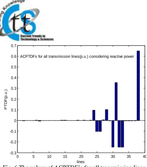
transmission lines for linear ATC in graphical form. Fig. 5 shows the values of ATC for all transmission lines using AC Power Flow. Fig. 6 the values of ACPTDF’s for all transmission lines considering. reactive power. Fig. 7 the values of ATC for all transactions using AC Power Flow for reactive power. Table 1 shows the comparison of ATC values calculated using AC & DC power flow methods with sample calculations.
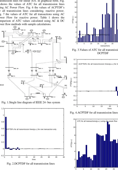
Fig. 1.Single line diagram of IEEE 24- bus system
Fig. 2.DCPTDF for all transmission lines
Fig. 3.Values of ATC for all transmission lines using DCPTDF
Fig. 4.ACPTDF for all transmission lines for linear ATC
Fig. 5.The values of ATC for all transmission lines using AC Power Flow
0 5 10 15 20 25 30 35 40
-0.2 0 0.2 0.4 0.6 0.8 1 1.2
lines
P
T
D
F
(p
.u
.) DCPTDFs for all transmission lines(p.u.) for one transaction only
0 5 10 15 20 25 30 35 40
0 2 4 6 8 10 12 14 16 18
transactions
A
T
C
(p
.u
.)
ATC for all three single transactions(p.u.)
0 5 10 15 20 25 30 35 40
-0.3 -0.2 -0.1 0 0.1 0.2 0.3 0.4 0.5 0.6 0.7
lines
P
T
D
F
(p
.u
.)
ACPTDFs for all transmission lines(p.u.) for linear ATC
0 5 10 15 20 25 30 35 40
0 2 4 6 8 10 12
transactions
A
T
C
(p
.u
.)
Fig. 6.The values of ACPTDF’s for all transmission lines considering. Reactive Power
Fig. 7.The values of ATC for all transactions using AC Power Flow for reactive power
Table(1)comparison of ATC values using AC & DC Power Flow methods with sample calculations
Sample Calculation
MATLAB Software Calculation
Method used ATC for
Transmission line (1- 2)
ATC for Transmission line
(1- 2) DC power
flow
1.85 1.75
AC power flow
1.85 1.85
6. C
ONCLUSIONATC is calculated using AC & DC power flow methods. The system is assumed to be intact. ATC calculation using DC power flow method is very fast because of no iterations. Most of the time this method is usedto find the ATC, before any transaction. By this method operators can easily choose the maximum ATC value transaction, to maximize their profit. This method gives the approximate values of ATC, by which we can get a rough idea of ATC values without using much time. This simply gives an idea about the best transaction based on the value of ATC. But the AC power flow method is very accurate method of ATC calculation. The reactive power is also considered in this method. It is seen from the results that the ATC found by AC power flow method is less than the ATC found by DC power flow method.
R
EFERENCES[1] Federal Energy Regulatory Commission (FERC),
“Regional Transmission Organizations”,
Washington, DC, Docket RM99-2-000, order 2000, Dec. 20, 1999.
[2] http://www.oasis.oati.com/wasn/index.html.
[3] North American Electric Reliability Council
(NERC), “Available Transfer Capability
Definitions and Determination”, NERC Report, June 1996.
[4] M. Armando Leite da Silva, Joao Guilherme de Carvalho Costa, Luiz Antonio da Fonseca Manso and J. George Anders, “Transmission Capacity: Availability, Maximum Transfer and Reliability”, IEEE Transactions on Power Systems, Vol. 17, No. 3, pp. 843-849, 2002.
[5] Gravener, M., Nwankpa, H. C., & Yeoh, T., “ATC Computational Issues”, InternationalConference on Power System, Hawaii, pp. 1-6, 1999.
[6] V. Ajjarappu and C. Christy, “The Continuation Power Flow: A Tool for Steady State Voltage Stability Analysis”, IEEE Trans. on Power Systems, vol. 7, no. 1, pp. 416-423, Feb. 1992. [7] O.Alsac and B. Stott, "Optimal Load Flow with
Steady State Security", IEEE Transactions on Power Apparatus and Systems, Vol. PAS-93, No. 3, pp. 745-751, 1974.
[8] Jitendra Kumar and Ashwani Kumar, “Multi-Transaction ATC Determination using PTDF Based Approach in Deregulated Markets”, Annual IEEE India Conference - INDICON, pp. 1-6, 2011.
[9] Jitendra Kumar and Ashwani Kumar, “ACPTDF for Multi-Transaction ATC Determination in Deregulated Market”, International journal of Electrical & computer engineering, vol. 1, no. 1, pp. 71-84, 2011.
[10] B.V.Manikandan, S. Charles Raja, P.Venkatesh
0 5 10 15 20 25 30 35 40
-0.3 -0.2 -0.1 0 0.1 0.2 0.3 0.4 0.5 0.6 0.7
lines
P
T
D
F
(p
.u
.)
ACPTDFs for all transmission lines(p.u.) considering reactive power
0 5 10 15 20 25 30 35 40
0 2 4 6 8 10 12
transactions
A
T
C
(p
.u
.)
Copyright © 2014 CTTS.IN, All right reserved Determination in the Restructured Electricity
Market", Electric Power Component and Systems, Taylor and Francis, 2008.
[11] Santiago Grijalva, Peter W. Sauer, “Reactive power considerations in ATC computation”, Decision Support Systems 30_2001.327–340.
[12] Konrad Purchala, Student Member, IEEE,
Leonardo Meeus, Daniel Van Dommelen, Senior
Member,” Usefulness of DC Power Flow for
Active Power Flow Analysis”.
[13] S.Nagalakshmi, S.Kalyani, V.Alamelu Shobana, R.Naga Ranjeni and P.Deepamangai,” Estimation of Available Transfer Capability under normal and contingency conditions in Deregulated Electricity Market”, IEEE-International Conference On
Advances In Engineering, Science And
Management (ICAESM-2012) March 30, 31, 2012.
[14] Chong Suk Song*, Chang Hyun Park**, Minhan Yoon * and Gilsoo Jang,” Implementation of PTDFs and LODFs for Power System Security”, Journal of International Council on Electrical Engineering Vol. 1, No. 1, pp. 49~53, 2011.
A
UTHORSP
ROFILESatish completed his master’s degree in Power System (EE) from Deen Bandhu Chotu Ram University of
Science and Technology, Murthal (Sonipat) –
HARYANA, INDIA.