DISCOVERY OF COMPLEX MODEL IMPLEMENTATION PATTERNS
IN SOURCE CODE
Linas Ablonskis, Lina Nemuraitė
Kaunas University of Technology, Department of Information Systems Studentų St. 50, LT−51368 Kaunas, Lithuania
e-mail: [email protected], [email protected]
Abstract. We present a method for discovering complex model implementation patterns in a hand written program code. A model implementation pattern is understood as a repeatedly used humanly meaningful transformation from a set of model elements to a piece of corresponding program code. Complex model implementation patterns are compo-sed from atomic model implementation patterns treated as black boxes. We use the same definition of model imple-mentation pattern for recognizing impleimple-mentation patterns and generating program code. The method is applied for automated configuring a program code generator.
Keywords: complex implementation pattern, atomic implementation pattern, implementation pattern recognition, model to code transformation, program code generator configuration, MDA.
1. Introduction
In Model Driven Architecture (MDA) [1] related software development, program code generators are used to automatically produce program code from program models. In order to work, program code generators must be provided with program code templates and template application rules. Currently all these configuration data must be written by hand, which is a labor intensive process [2] requiring a lot of expertise to execute correctly [3]. We have proposed a program code generator that can configure itself auto-matically by recognizing the patterns that human has used to write a partial program code and exploit those patterns to generate program code for yet unimple-mented model elements [4]. In our previous work we have created an algorithm that allows recognition of simple, atomic model implementation patterns [5]. In this work we describe a method that allows defining and recognizing complex model implementation pat-terns composed from atomic model implementation patterns described earlier [5].
The remainder of this paper is structured as fol-lows: in Section 2 we present related works; in Sec-tion 3 we present models used to express program mo-del and code together with atomic and complex momo-del implementation patterns, called atomic and complex transformations; in Section 4 we present an algorithm for detecting complex transformations in a program code; Section 5 is devoted for method testing; and fi-nally in Section 6 we provide conclusions and outline the future work.
2. Related works
Model driven development has become the com-mon practice of creating software related artifacts. The main principles of model driven development are se-paration of concerns and raising level of abstraction. A program code generator is the definitive component of model driven development chain. The program code generation is strictly separated from other levels of MDA and can be performed from such artifacts as ontologies, business process models, business rules, domain models, or design models [6–10]. When rela-ted techniques are applied to produce one kind of mo-dels from other kind of momo-dels, the process is known as transformation [11]. Program code generation intrinsically depends on technology and domain changes; therefore, it is not efficient in quickly chang-ing world. Currently, researchers are lookchang-ing for more efficient ways of creating program code generators e.g. using meta-programming [12] or domain specific languages [13]. Our idea for improving program code generation is to separate transformations that are used to generate program code from the actual program-ming language that the generated program code must be expressed in. Also, the manner of program model traversal used for generating program code in our me-thod differs from conventional approaches because we use formal concept analysis to select the sets of model elements that can be implemented by an application of a specific pattern.
the area of design pattern recovery. Design patterns [14] are reusable solutions to common software en-gineering problems modeled by a certain composition of software artifacts. Design pattern recovery methods find instances of design patterns in a program code and are primarily used to assist program comprehen-sion.
Some design pattern recovery methods use static analysis of program code to extract available elements and their relationships and dynamic analysis to extract execution traces and call graphs. The data received from static analysis are enriched with data received from dynamic analysis and analyzed by a set of prede-fined algorithms made to detect a single design pattern [15, 16]. Alternatively, only data from static analysis can be used [17].
A variation [18] is to use graphs for describing de-sign pattern templates and an algorithm that evaluates edge similarity of two graphs [19] for finding corres-pondences between design pattern templates and a source code element tree. While not published as a de-sign pattern recovery method, a similar approach [20] uses attributed flow graphs to describe both design patterns and program code. The flow graph based de-scriptions of design patterns are treated as graph gram-mars and a special algorithm [21] is used to find the places in a program code flow graph that match the flow grammar expressions of design patterns. Design pattern detection can also be considered to be a const-raint satisfaction problem where each design pattern provides a constraint on a set of elements and relations that compose it [17]. There are suggestions [22, 23] to use XML based language for describing design pat-terns and then applying the same principle to detect them.
Since design pattern detection algorithms can be computationally expensive, there is a work that finger-prints design patterns through a set of code metrics (size, filiations, cohesion and coupling) and then uses these fingerprints to quickly reject invalid candidates before employing standard design pattern recovery techniques [24]. This requires a rule engine and an initial source code base for teaching that rule engine. There is also a method that uses decision trees and neural networks for recognizing design patterns through code metrics [25]. The neural networks must be trained by supplying manually evaluated design pattern candidates extracted from sample source code.
Another approach is to describe design patterns with logical formulas that operate on a set of predica-tes extracted from source code [26]. These predicapredica-tes describe the existence of various types of elements and relationships in a parsed program code. The predicates extracted from the source code and logical formulas describing design patterns are fed to a logic engine. The advantage of this method is its ability to find non-standard variants of design patterns, as long as they can be logically reduced to a standard form. There is a paper [27] that suggests standardization of logic predicates used for program code analysis as this
would allow making a tool working with a wide variety of programming languages as long as there are suitable extractors for those languages.
Finally, there is a design pattern recovery method that uses formal concept analysis [28] to analyze a set of predicates extracted from program code when de-tecting design patterns [29]. Predicates describe exis-tence of entities and their relationships. Application of formal concept analysis enables detection of ad-hock design patterns and does not require design pattern definitions. However, results must be manually inter-preted by a human.
The direct application of design pattern recovery methods proved to be unsuitable for our needs. Predi-cates-with-logical-formulas, one-algorithm-per-pattern and graph-subgraph-matching methods require a lot of work for building predicate sets, logical formulas, algorithms or graphs that correspond to artifacts being detected. Code metrics and Artificial Intelligence (AI) based methods are either approximate, or they only use code metrics and AI techniques to quickly reject candidates. Ad-hoc design pattern detection method [29] is unsuitable for our needs as it will detect some-thing that can be viewed as design patterns, but it will always need a human to comprehend the meaning of those design patterns. Also, we wanted to use the same definition of a program model implementation pattern both for pattern recognition in a program code and program code generation, which is not possible with design pattern models used in existing methods for recovery of design patterns. To satisfy our needs, we have created algorithms for model implementation pattern definition and model implementation pattern recognition while taking the inspiration from the graph-subgraph matching based design pattern reco-very methods [17, 19].
From the perspective of program code generation, a model implementation pattern, as it is understood in our work, is conceptually equal to the program code template together with template application rules [11]. While the usual way to define program code templates is in a textual form, we define model implementations patterns as transformations from an abstract represen-tation of a program model to an abstract represenrepresen-tation of a program code in an effort to make our method a modeling and programming language agnostic. The meta-model of complex model implementation pat-terns used in our work allows expression of simple blocks, iterators and conditional evaluation matching only the basic expression capabilities of other temp-late languages commonly used for program code gene-ration, such as Velocity [30], XSLT [31], Xpand [32], JET [33], etc. Relatively weak expression capabilities of complex model implementation patterns are par-tially compensated by the fact that they are built from atomic model implementation patterns, which are defined as black box functions, allowing any comp-lexity inside.
analyzing generated source code and recognizing templates that were used to generate it, by using the same definition of a program code template for both tasks [34]. The method is independent from source code language; however, it cannot recognize reordered program code and cannot reverse engineer program code directly into the same level of abstraction that it was generated from. Thus it is unsuitable to analyze hand written program code and does not fit our needs.
3. Specifying model implementation patterns
A model implementation pattern describes how a piece of a program model can be expressed in a piece of program code. Thus a model implementation pat-tern is a transformation from a piece of program mo-del to a piece of program code. From now on we will call complex model implementation patterns as comp-lex transformations and simple, atomic model imple-mentation patterns as atomic transformations.
The method for definition and recognition of complex transformations presented in this paper is based on our previous work dedicated to definition and recognition of atomic transformations, called basic transformations in the previous paper [5]. Since then we have devised a slightly improved model for definition of atomic transformations and a slightly im-proved algorithm for detecting instances of atomic transformations in a program code that we will briefly present here.
We represent elements of a program model through instances of model concepts and elements of a program code through instances of code concepts. Both types of concepts can be joined in respective concept graphs. A concept is an instance of a concept template. Each unique concept template corresponds to some unique concept in a modeling or program-ming language. An example of modeling language concepts can be taken from Unified Modeling Lan-guage (UML) [35]: class, interface, method, etc. An example of programming language concepts can be taken from Java language: package, class, method, loop, conditional branch, etc.
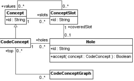
A concept has a set of slots and a set of attributes. Slots are used for building concept graphs and contain references to other concepts in a graph. Attributes are used to store literal values that describe a literal property of the concept. In our previous work we had to split base hierarchies of model concepts into concept, concept-with-name and concept-with-value branches to express name and value attributes. Current model of attributes allows defining the same things and more while retaining single base types of model and code concepts. The new concept meta-model is shown in Figure 1.
Model concept graphs are used to represent models and code concept graphs are used to represent program code. Model concepts and model concept graphs follow the meta-model shown in Figure 2.
Figure 1. A common part of model and code concept meta-models
Figure 2. Meta-model of model concepts and model of model concept graphs
A model concept graph is represented by a container that allows accessing top model concepts. Top model concepts are considered to be those that represent top containers in a program model.
Code concepts and code concept graphs follow the meta-model shown in Figure 3.
Figure 3. Meta-model of code concepts and model of code concept graphs
Holes are used to specify possible connection points to other code concept graphs. A hole has a unique identifier id and a function accept that returns if given code concept can be placed into a hole. A code concept graph is represented by a container that allows accessing top code concepts. Top code cepts are considered to be those that represent top con-tainers in a program code.
elements into program code elements as black box functions and are discussed in our previous paper under the name of basic transformations [5]. Complex transformations, the subject of this paper, are made by composing atomic transformations and are designed to describe complex humanly meaningful mappings of program model elements into program code elements. The requirement for transformations to be humanly meaningful has a twofold purpose. First, it limits the number of possible transformation functions. Second, it allows credible application of transformations for analysis of a hand written program code, because hand written program model implementation in a program code is a result of a humanly meaningful transfor-mation from a program model to a program code.
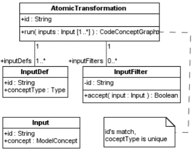
The meta-model of atomic transformations is shown in Figure 4.
Figure 4. Meta-model of atomic transformations
An atomic transformation function run takes a list of inputs and produces a code concept graph with holes. Holes mark points where other code concept graphs may be attached when joining the outputs of several atomic transformations. A list of input defi-nitions inputDef tells what number and kind of inputs are accepted by an atomic transformation. A list of in-put filters inputFilters defines additional conditions for valid inputs of an atomic transformation. The ato-mic transformation function run accepts a list of in-puts that must follow the list of input definitions and distinguishes individual inputs by the corresponding id field. A valid input definition list must have no input definitions with matching conceptType; this condition is necessary for correct operation of the algorithm that detects instances of atomic transformations in a prog-ram code.
The meta-model of complex transformations is shown in Figures 5–8.
A complex transformation has a list of input definitions inputDefs specifying the number and type of model concepts that the transformation accepts. When complex transformation is executed, it is sup-plied with a list of inputs that match the input defini-tions. Complex transformation has a list of input fil-ters inputFilters that can be used to impose additional
restrictions on valid inputs. Input filters are based on white box condition expressions. Complex transfor-mation also has a body that is a tree of atomic trans-formation wrappers and control nodes as shown in Figure 6.
Figure 5. Meta-model of a complex transformation
Figure 6. Model of a complex transformation body
An atomic transformation wrapper node BnAtf re-ferences a single atomic transformation and specifies how to provide the inputs of that atomic transforma-tion from the inputs of host complex transformatransforma-tion. Atomic transformation inputs are provided through a list of input paths, described further in the text. Ato-mic transformation wrapper also contains a list of joints that place other body nodes of complex trans-formation into holes of code concept graphs produced by atomic transformation functions.
A loop node BnLoop takes a list of model concepts provided by a given input path and evaluates its body for each of those concepts. Input paths within loop body can read the value of loop iterator. Strict loops are supposed to iterate at least once, non strict loops can iterate zero times.
A conditional evaluation node BnIf has a list of branches that contain conditions. The first branch whose condition is satisfied has its body evaluated. Strict conditional nodes are supposed to evaluate a bo-dy of one branch; non strict conditional nodes are allo-wed to evaluate zero branches.
IpnInput node reads from a given input of a complex transformation and can be followed by IpnSlot, IpnOne and IpnFilter. IpnSlot node reads from the gi-ven concept slot and can be followed by IpnSlot, IpnOne and IpnFilter. IpnOne node selects one con-cept from the list and can be followed by IpnSlot. IpnFilter node rejects concepts from a list and can be followed by IpnOne. IpnLoop selects the current ite-rator value of a given loop and can be followed by IpnSlot. IpnLoop must be used only inside the body of the loop it extracts from.
Figure 7. Model of input paths
Figure 8. Model of white box conditions
Finally, white box condition expressions (Figure 8) are used for filtering the inputs of complex transfor-mation and branches of conditional evaluation nodes. Leaf nodes of the expression are CnInputPath nodes that specify an input path and a condition function on its result. CnAnd node corresponds to logical conjunc-tion of its operands, CnOr node to logical disjunction and CnNot to negation.
4. Detecting complex model implementation patterns
The method for detecting the presence of atomic transformation instances in a program code is descri-bed in our previous paper [5]. The algorithm works with code concept trees, but can be trivially improved to operate on code concept graphs by adding the sup-port for graph cycle avoidance with a simple trace of nodes being visited. In our current work, we use the improved version. Detections of atomic transforma-tion instances correspond to the model shown in Fi-gure 9. Fields of an atomic transformation instance detection have the following meaning: atf – an atomic transformation, inputs – inputs to atomic transforma-tion, output – output of atomic transformation and matches – a list of code concepts from the given code concept graph that matched top code concepts of an atomic transformation output.
Figure 9. Model of an atomic transformation instance detection
This way, instances of AtfDetection specify the atomic transformation instance detected and the start-ing position of a detection in a given code concept graph.
By exploiting the ability to detect instances of ato-mic transformations in a program code, we can also detect instances of complex transformations. For this, we take complex transformations one by one and de-tect how they relate parts of given program model with parts of given program code. The outline of the algorithm for detecting complex transformation ins-tance is shown in Figure 10.
Given a model concept graph, we compose a list of all model concepts present and create an input space for a given complex transformation by composing lists of model concepts that satisfy input definitions and pass input filters (Figure 10, action 1). Then we prune the input space by removing inputs for which we can prove that using those inputs will result in a failure of complex transformation evaluation in every possible scenario (Figure 10, action 2). To prune the input space, a complex transformation is roughly emulated and all members of a given input space are verified against input paths found in complex transformation body. If some member of an input space fails an input path at every possible execution scenario of a complex transformation, it is thrown out.
Once the input space is pruned, we start making permutations of inputs (Figure 10, action 3) and for each permutation we evaluate a complex transforma-tion (Figure 10, actransforma-tion 4). Evaluatransforma-tion of a complex transformation can fail. Failure can happen if at some point of complex transformation evaluation it is found that some input path cannot be evaluated due to in-compatible model structure or if some input path, when evaluated, produces model concept that is not accepted by a filter of atomic transformation used in some body node. If evaluation of a complex trans-formation fails against some permutation of inputs, we skip that permutation and move on to the next one.
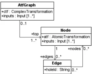
If evaluation of a complex transformation suc-ceeds, the result is a graph of nested atomic transfor-mation instances that corresponds to a model shown in Figure 11.
Figure 11. Model of atomic transformation instance graphs
AtfGraph represents an instance of an atomic transformation instance graph where field ctf points to a complex transformation whose instance is de-scribed by a graph and field inputs stores inputs of that complex transformation instance. A graph has a set of nodes represented by a class Node. Each node points to an atomic transformation through field atf and field
inputs stores inputs of that atomic transformation. Each node has a list of edges represented by a class Edge. Each edge corresponds to a hole in an atomic transformation represented by a source node. The id of that hole is stored in a field holeId. Each edge points to a list of destination nodes.
An atomic transformation instance graph repre-sents a partially evaluated complex transformation with loops unrolled, conditional branches selected and input paths evaluated. Since we can detect instances of atomic transformations in code concept graphs, any code concept graph together with a set of atomic transformation instances detected in that graph can be used to detect complex transformation instances repre-sented by atomic transformation instance graphs.
Once an evaluation of a given complex transfor-mation produces an atomic transfortransfor-mation instance graph G, the complex transformation instance detec-tion process starts traversing the code concept graph, that represents a given program code (Figure 10, ac-tion 5). Each step of traversal produces a set of sibling code conceptsS. For eachS, a set Bof atomic trans-formation instance detections is composed, where each atomic transformation instance detection b∈B starts with code concepts from S. Then a list M of atomic transformation instance detections from B with related coverage values is composed for every top node ofG.
Let us defineA as a set of all nodes inG. To com-pute the coverage of some a∈A over someb∈B,
a is overlaid on top of b and the best possible match of the atomic transformation instance graphs that start with a and b is found. Once the match is found, the graph that starts with a is taken and the coverage is computed by dividing the number of matched nodes by the number of nodes in the graph. This yields the coverage value in range [0; 1], where 0 means that there is no match between the graphs spanned by a and b and 1 means that there is a total match. The algorithm for that is shown in Figure 12.
def checkMatch(node : Node, atfd : AtfDetection) : Match = { val theMatch = new Match(node = node, atfd = atfd);
if( node.atf.id != atfd.atf.id) return theMatch;
val inputsMatch = check if items from node.inputs matches items in atfd.inputs; if( !inputsMatch ) return theMatch;
theMatch.coverage.raw = 1; for( edge <- node.edges ) {
val hole = the hole in atfd.output having the same id as edge.holeId;
val holeConcepts = concepts in a given code concept graph that fall into the hole; val holeAtfds = atomic transformation instance detections that start with holeConcepts, except those that rely on concepts consumed by the atfd;
var matchLists = List[List[Match]](); for( dstNode <- edge.nodes ) {
var matchList = List[Match](); for( holeAtfd <- holeAtfds ) {
val holeAtfdMatch = check(dstNode, holeAtfd); if( holeAtfdMatch.coverage.raw > 0 )
matchList = matchList :+ holeAtfdMatch; }
if( matchList.size > 0 ) matchLists = matchLists :+ matchList; }
bestMatchPerm = make permutations from the items in match lists; each permutation does not contain two matching atomic transformation instance detections; find permutation with the best unit coverage;
theMatch.matches = theMatch.mathes ++ bestMatchPerm; }
calculate the total raw and unit coverage of the match by using coverage information from the sub matches and total size of the sub graph that starts with the node;
return theMatch; }
Figure 12. The algorithm for computing the match between a node of an atomic transformation instance graph and atomic transformation instance detection
val atfds : List[AtfDetection]() = …; val graph : AtfGraph = …;
var matchLists = List[List[Match](); for( node <- graph.top ) {
var matchList = List[Match](); for( atfd <- atfds ) {
val theMatch = checkMatch(node, atfd); if( theMatch.coverage.raw > 0 )
matchList = matchList :+ theMatch; }
if( matchList.size > 0 ) matchLists = matchLists :+ matchList; }
val perms = a list of permutations from the items of matchLists where in each permutation there are no items with matching atomic transformation instance detections;
for( matchPermutation <- perms )
register a detection from a matchPermuation
Figure 13. The algorithm for recognizing the complex transformation instance graph in a given code concept graph with atomic transformation instance detections
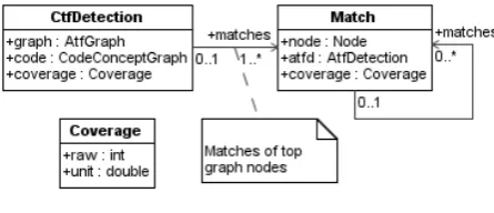
A model of complex transformation instance de-tection is shown in Figure 14.
Figure 14. Model of complex transformation instance detections
Complex transformation instance detection stores an atomic transformation graph that was detected, a code where detection took place, a coverage
measurement, and a list of matches for top nodes of the graph. Each match stores a node of an atomic transformation instance graph and a corresponding atomic transformation instance detection atfd together with coverage measurement stored as coverage and a list of submatches matches. Each coverage measure-ment is represented by two fields. The field raw describes how many nodes (and sub nodes) have been detected to match. The field unit stores a normalized coverage value in range [0; 1] computed as raw/total-Nodes where totalNodes is a total number of nodes in an atomic transformation instance graph, or in a case of a single match, a total number of nodes in a sub-graph that starts with the head node of the match.
algorithm described in the complex transformation and the measure of that relation can be normalized into an interval [0; 1] where 0 means that complex transformation instance was not detected at given point at all, and 1 means that complex transformation instance fully matches program code at a given point. Since a complex transformation represents a complex program model implementation pattern, detection of some complex transformation instances are recogni-tions of related model implementation patterns in a program source code.
5. Method testing
We have used the method for definition and recog-nition of complex transformations, described in this paper, to implement an automatically configured prog-ram code generator that can detect progprog-ram model im-plementation patterns in a partial handwritten source code provided by a human and automatically use those patterns to generate program code for yet unimple-mented model elements. The in-depth description of an automatically configured program code generator includes the method for detecting implementation si-milarity of program model elements and is beyond the scope of this paper.
We have performed the experiment to validate and test the prototype of an automatically configured prog-ram code generator. Inherently, the method of complex transformation instance detection got tested as well. The experiment was supplied with the sample sets of atomic transformations (15 items), complex transfor-mations (8 items) and a sample set of model and code concepts, together with transformations from UML models to model concept graphs and bidirectional transformations between Java code and code concept graphs.
The model concept set allowed expression of packages, classes, interfaces, class and interface deri-vations, class and interface properties, stereotypes and stereotype applications, class and interface operation definitions, primitive and non primitive types and va-rious associations. The code concept set allowed ex-pression of array related definitions and operations; the concept of value assignment; various control flow related concepts; concepts for the definition of prog-ram artifacts, such as classes, interfaces, methods, va-riables, etc; concepts for object oriented programming such as type cast and instance creation; literal value definitions and a type reference concept.
Complex transformations provided several types of mappings from model classes and interfaces to code classes and interfaces with varying levels of infor-mation transfer. Atomic transforinfor-mations provided the primitive mappings between individual types of model elements and related code concept graphs that were necessary to express the complex transformations.
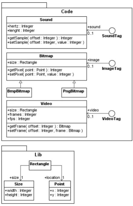
The experiment was supplied with the input model shown in Figure 15.
Figure 15. An input model used for experiment
The sample implementation of classes Sound, Point and interface SoundTag were used to drive the configuration of a program code generator and thus were the ones were the recognition of complex trans-formation instances took place. The implementations of other classes and interfaces were generated by ap-plying the complex transformation whose instance was detected in a related sample implementation of Sound, Point or SoundTag.
The experiment was performed in seven steps. The first step has provided simple POJO (Plain Old Java Object) implementations of the classes Sound, Point and interface SoundTag. The second step added pro-perty accessor methods to implementation of Sound. The third step added property accessor methods to implementation of Point. The fourth step has provided implementation of Sound through class and interface pair. The fifth step has provided the implementation of SoundTag as interface and interface adapter pair. The sixth step has once again added property accessor methods to previous implementation of Sound. And the seventh step has added property accessor methods to the previous implementation of SoundTag.
7 steps with 3 sample implementations per step a total of 21 sample pieces of code were examined in respect to a total of 8 complex transformations and the pre-sence of complex transformation instances and the de-gree of complex transformation instance coverage were correctly detected each time.
6. Conclusions and future work
We have created a method that allows detecting complex program model implementation patterns in a handwritten program code. The method was used in an automatically configured program code generator that can detect program model implementation patterns in a partial handwritten program code and use those implementation patterns to generate program code for yet unimplemented model elements. We have defined program model implementation patterns as humanly meaningful transformations from pieces of program model to pieces of program code and have graded them into atomic and complex where atomic model implementation patterns are black box model-to-code transformation functions and complex model imple-mentation patterns are composed from atomic ones. Our method allows using the same definition of an implementation pattern both for recognitions and program code generation purposes.
While the usual way to define program code gene-rator templates uses a textual form, we define model implementation patterns as transformations from an abstract representation of a program model to an ab-stract representation of a program code in an effort to make our method of implementation pattern recogni-tion a modeling and programming language agnostic. The meta-model of complex model implementation patterns used in our work allows expression of simple blocks, iterators and conditional evaluations.
In certain cases it may be desirable to use the abbreviated version of a complex transformation for implementation pattern detection and the longer ver-sion for program code generation. Addition of such feature would require appending the complex trans-formation meta-model with artifacts for differentiating between the parts used for complex transformation detection and the parts used for program code genera-tion. On that score, the essence of complex transfor-mation detection algorithm would not change.
Current model of complex transformations cannot express the difference between complex transforma-tion parts where ordering of sibling elements matters and those parts where it does not, thus either one or another must be assumed for the whole complex trans-formation. Current complex transformation instance detection algorithm assumes that ordering of sibling elements does not matter. Removing this weakness re-quires adding scope constructs into complex transfor-mation model and supporting those constructs in a complex transformation instance detection algorithm.
References
[1] J. Bézivin. On the unification power of models. Soft-ware and Systems Modeling, 4(2), 2005, 171–188.
[2] R.L. Glass. Some Thoughts on Automatic Code Ge-neration. ACM SIGMIS Database, 27(2), 1996, 16-18.
[3] J. Herrington. Code generation in action. Manning Publications Co, 2003.
[4] L. Ablonskis. An approach to generating program code in quickly evolving environments. In G. A. Papa-dopoulos, G.. Wojtkowski, W. W. Wojtkowski, S. Wry-cza, J. Zupancic (Eds.): Information Systems Develop-ment: Towards a Service Provision Society, Springer-Verlag: New York, 2009, 259–267.
[5] L. Ablonskis, L. Nemuraitė. Discovery of model im-plementation patterns in source code. Information Technology and Control, 39(1), 2010, 68–76.
[6] A. Čaplinskas, A. Lupeikienė, O. Vasilecas. Shared Conceptualization of Business Systems, Information Systems and Supporting Software. In Haav, H.-M.; Kalja, A. (Eds.): Databases and Information Systems II. Fifth International Baltic Conference "Baltic-DB&IS'2002", June 3-6, 2002, Tallinn, Estonia. Dord-recht / Boston / London: Kluwer Academic Publishers, 2002, 109–120.
[7] O. Vasilecas, D. Kalibatienė, G. Guizzardi. Towards a Formal Method for the Transformation of Ontology Axioms to Application Domain Rules. Information Technology and Control, 2009, 38(4), 271–282.
[8] O. Vasilecas, S. Sosunovas. Practical Application of BRTL Approach for Financial Reporting Domain. In-formation Technology and Control, 2008, 37(2), 106– 113.
[9] T. Skersys. Business Knowledge-Based Generation of the System Class Model. Information Technology and Control, 2008, 37(2), 145–153.
[10] A. Armonas, L. Nemuraitė. Using Attributes and Merging Algorithms for Transforming OCL Expres-sions to Code. Information Technology and Control, 2009, 38(4), 283–293.
[11] K. Czarnecki, S. Helsen. Classification of model transformation approaches. OOPSLA2003, Workshop on Generative Techniques in the Context of MDA, 2003 Anaheim, CA, USA.
[12] R. Damaševičius, V. Štuikys. Taxonomy of the Fun-damental Concepts of Metaprogramming. Information Technology and Control, 2008, 37(2), 124–132.
[13] J.R. Cordy. Eating our own dog food: DSLs for gene-rative and transformational engineering. In GPCE '09: Proceedings of the eighth international conference on Generative programming and component engineering, October 2009, ACM, 3–4.
[14] E. Gamma, R. Helm, R. Johnson, J. Vlissides. De-sign Patterns – Elements of Reusable Object-Oriented Software. Addison-Wesley Publishing Co., 1995.
[15] D. Heuzeroth, T. Holl, G. Högström, W. Löwe.
Automatic design pattern detection. In proceedings of the 11th IEEE International Workshop on Program Comprehension, 2003, 94–103.
[17] H. Albin-Amiot, P. Cointe, Y.G. Guéhéneuc, N. Jussien. Instantiating and detecting design patterns: putting bits and pieces together. In proceedings of the 16th Annual International Conference on Automated Software Engineering, 2001, 166–173.
[18] N. Tsantalis, A. Chatzigeorgiou, G. Stephanides, S.T. Halkidis. Design pattern detection using simila-rity scoring. IEEE Transactions on Software Enginee-ring, 32(11), 2006, 896–909.
[19] V.D. Blondel, A. Gajardo, M. Heymans, P. Senel-lart, P.Van Dooren. A measure of similarity between graph vertices: applications to synonym extraction and web searching. SIAM Review, 46(4), 2004, 647–666.
[20] C. Rich, L.M. Wills. Recognizing a program's design: a graph-parsing approach. IEEE Software, 7(1), 1990, 82–89.
[21] D.C. Brotsky. An Algorithm for Parsing Flow Graphs. Technical report TR-704, MIT Artificial In-telligence Laboratory, 1984.
[22] Z. Balanyi, R. Ferenc. Mining design patterns from C++ source code. In proceedings of the International Conference on Software Maintenance, 2003, 305–314.
[23] J.M. Smith, D. Stotts. SPQR: Flexible automated de-sign pattern extraction from source code. In procee-dings of the 18th IEEE International Conference on Automated Software Engineering, 2003, 215–224.
[24] Y-G. Gueheneuc, H. Sahraoui, F. Zaidi. Fingerprin-ting design patterns. In proceedings of the 11th Working Conference on Reverse Engineering, 2004, 172–181.
[25] R. Ferenc, A. Beszedes, L. Fulop, J. Lele. Design pattern mining enhanced by machine learning. In proceedings of the 21st IEEE International Confe-rence on Software Maintenance, 2005, 295–304.
[26] J. McC. Smith, D. Stotts. Elemental design patterns: A logical inference system and theorem prover support for flexible discovery of design patterns. Technical Report TR02-038, Department of Computer Science, University of North Carolina, 2002.
[27] J. Fabry, T. Mens. Language independent detection of object-oriented design patterns. Computer Lan-guages, Systems & Structures, 30(1-2), 2004, 21–33.
[28] R. Wille. Formal Concept Analysis as Mathematical Theory of Concepts and Concept Hierarchies. Formal Concept Analysis, Springer, 2005, 1-33.
[29] P. Tonella, G. Antoniol. Object Oriented Design Pat-tern Inference. In proceedings of the 5th Symposium on Software Development Environments, 1999, 230– 238.
[30] Apache Velocity. [interactive][accessed 2010-09-20]. http://velocity.apache.org/.
[31] W3C consortium. XSLT specification. [interactive] [accessed 2010-09-20]. http://www.w3.org/TR/xslt.
[32] Eclipse Modeling, Model to Text, Xpand. [interactive] [accessed 2010-09-20].
http://www.eclipse.org/modeling/m2t/?project=xpand.
[33] Eclipse Modeling, Model to Text, JET. [interactive] [accessed 2010-09-20].
http://www.eclipse.org/modeling/m2t/?project=jet.
[34] M. Bork, L. Geiger, C. Schneider, A. Zündorf. To-wards Roundtrip Engineering – a Template-Based Re-verse Engineering Approach. In proceedings of the 4th European conference on Model Driven Architecture: Foundations and Applications, LNCS, 5095, 2008, 33– 47.
[35] OMG group. Unified modeling language: superstruc-ture. [interactive][accessed 2010-09-20].
http://www.omg.org/cgi-bin/doc?formal/07-02-03.