Integrated ring resonator system analysis to Optimize
the soliton transmission
I.S. Amiri1*, H Ahmad2, MZ Zulkifli3
1*,2,3
Photonics Research Centre, University of Malaya, Malaysia
*Corresponding author: Dr. IS Amiri, Photonics Research Centre, University of Malaya,50603 Kuala Lumpur, Malaysia. E-mail: [email protected], [email protected]. Tel.:+60127420567
The chaotic signals can be generated within the microring resonator (MRR) system when the Gaussian pulse with input power of 120 mW is inserted into the system. Generation of chaotic signals respect to the ring's radius has been studied. The coupling coefficient affects the output power significantly, thus in order to generate signals with higher output power, the smaller coupling coefficient can be used. Here the output power of the system is characterized with respect to the different coupling coefficients of the system.A series of MRRs connected to an add/drop filter system in order to anaylize the soliton signals. The nonlinear refractive index of the MRR is n2=2.2 x 10
-17
m2/W. The capacity of the output signals can be increased through generation of peaks with smaller full width at half maximum (FWHM). Here, we generate and characterize the ultra-short optical soliton pulses respect to the ring's radius and coupling coefficients variation of the system. As result, soliton pulses with FWHM and free spectral range (FSR) of 50 pm and 1440 pm are generated.
Keywords: Chaotic signals, microring resonator (MRR), ultra-short solitons, finesse, soliton transmission
INTRODUCTION:
To generate a spectrum of light over a broad range, an optical Gaussian pulse is recommended as a powerful laser pulse that can be used to generate chaotic signal when propagate within nonlinear MRRs. In optical communication, Gaussian controls within a semiconductor add/drop filter have numerous applications.MRRs are employed to generate signals used for optical communication applications, where they can be integrated into a single system.
Optical MRRs recently are interesting subject in the area of integrated optics because of their unique aspects such as compactness, low cost, tunability and easy integration on a chip with other photonic devices, having a variety of applications such as optical filter, optical switch, optical modulator, optical delay line, dispersion compensator, optical sensor and etc(Nawrocka et al., 2006; Xu et al., 2006; De Vos et al., 2007; Guarino et al., 2007). They are the types of Fabry-Pérot resonators, which can be readily integrated in array geometries for useful functions in areas such as optical communication(Rabus & Hamacher, 2001), signal processing in the nanoscale regime(Melloni & Martinelli, 2002; Dorfmüller et al., 2009). Its nonlinear phase response can also be readily incorporated into an interferometer system to produce a specific intensity output function.
Add/drop filter system which create or filter narrowband wavelength signals from wider optical spectrum and connected to the bus waveguide are generally basic foundations of building blocks in addition to optical communication devices(Sridhar, 1998; Yupapin & Suwancharoen, 2007). One interesting result emerges through the use of an add/drop system, which is a good candidate for nanoscale interferometer applications.Add/drop filters employing MRRs have established with regard to practical applications therefore optical resonator devices experience good quality factors. One new feature of this specific type of ring resonator, which introduces a system of
nanoscale-sensing transducers based on the add/drop ring resonator was presented by Amiri et al(I. S. Amiri et al., 2014).
They have shown that the multi-soliton can be generated and controlled within a modified add/drop ring resonator.Optical solitons are localized as electromagnetic waves that propagate in nonlinear media resulting from a balance between nonlinearity and linear broadening due to dispersion and/or diffraction. There are five types of nonlinear media which such as Kerr law, power law, parabolic law, dual-power law and the log law. In the presence of dispersive perturbation terms, the phenomena of optical soliton cooling are also observed. Initially soliton refer to the particle-like nature of solitary waves that remain intact even after common collisions.
The MRR performance can be described by several parameters namely free spectral range (FSR), full width half maximum (FWHM) and the finesse (FSR/FWHM). The high performance, low loss, high speed, low cost and simplicity both in fabrication and setup are needed in communication systems. Optical channel filters with low insertion loss, wide FSR (high selectivity) and high stop band rejection are required in such a system like dense wavelength multiplexing (DWDM).Many theoretical and experimental designs have been proposed to optimize the filter response and other properties using various coupling coefficients and radii.
THEORY OF THE RESEARCH
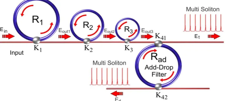
The system of the MRRs is shown in Figure 1.
Figure 1. A schematic of the proposed MRR's system, where Rs: ring radii,κs: coupling coefficients, Rd: an
add/drop ring radius, Aeffs: effective areas
The input optical fields
(
E
in)
in the form of Gaussian beam can be expressed by
i
t
L
z
E
t
z
E
D
in 0 0
2
exp
)
,
(
(1)Here
E
0and z are the optical field amplitude and propagation distance, respectively. The dispersion length ofthe soliton pulse can be defined as 2 2
0
T
LD , where
T
0 is the propagation time, the frequency carrier of the soliton is
0
2 are the coefficients of the second order terms of the Taylor expansion of the propagation constant(S. E. Alavi et al., 2014). The intensity of soliton peak is
| / 2|
0
2 T
, whereT
o is representing the initial soliton pulse propagation time. A balance should be achieved between the dispersion length (LD)and the nonlinear length)
/
1
(
L
NL
NL , where
n
2
k
0, is the length scale over which disperse or nonlinear effects causes the beambecomes wider or narrower.Here,LD LNL. The total index (n) of the system is given by(I. S. Amiri et al., 2013).
,
)
(
2 02
0
P
A
n
n
I
n
n
n
eff
Where
n
0 andn
2 are the linear and nonlinear refractive indices respectively.IandP
are the optical intensity and optical power, respectively.A
eff represents the effective mode core area of the device, where in the case of MRRs,the effective mode core areas range from 0.50 to 0.1 m2. The normalized output of the light field is defined as.
)
2
(
sin
1
1
4
)
1
1
1
(
)
)
1
(
1
(
1
)
1
(
|
)
(
)
(
|
2 2 2 2
x
x
x
t
E
t
E
in out (3)Here,
is the coupling coefficient,xexp
L/2
represents a round-trip loss coefficient,
0
NL,
0
kLn
0 and
NLkLn2Ein 2 are the linear and nonlinear phase shifts andk
2
/
is the wave propagation number and
is the fractional coupler intensity loss. HereL
and
are the waveguide length and linear absorption coefficient, respectively. The input power insert into the input port of the add/drop filter system.E
thandE
droprepresent the opticalelectric fields of the through and drop ports, respectively expressed by equations (4) and (5),
n d
L L L d n L out t
L
k
e
e
e
L
k
e
E
E
d d d dcos
1
1
2
1
1
1
1
cos
1
1
2
1
/
2 42 41 42 41 42 2 42 41 41 2 3 2
(4)
n d
L L L out d
L
k
e
e
e
E
E
d d dcos
1
1
2
1
1
1
/
2 42 41 42 41 2 42 41 2 3 2
(5)WhereEt 2 and Ed 2are the output intensities of the through and drop ports respectively..
RESULTS AND DISCUSSION:
For the first single ring resonator, the parameters were fixed to λ0=1.55 μm, n0=3.34, Aeff=30 μm 2
, α=0.01 dB mm−1, and γ=0.1. The length of the ring has been selected to L=60 μm, where the coupling coefficient is fixed to 0.0225 and the linear phase shift has been kept to zero. The total round-trip of the input pulse inside the ring system was 20,000. The ring resonator is considered as a passive filter system which can be used to generate signals in the form of chaos, applied in optical communication with regards to suitable parameter of the system. Figure 2 shows that bifurcation and chaotic behavior of the single ring resonator system, where the Gaussian beam with input power of 120 mW is used.
Figure 2. Bifurcation and chaos in single ring resonator with L=60 μm, where (a): Output intensity (mW/μm2) versus round-trip, (b): Output intensity (mW/μm2
Beside the ring resonator' radius parameter, the coupling coefficient of the single ring resonator also is considered to be an effective parameter to determine the output intensity power of the system. In order to characterize the ring resonator system based on the coupling coefficient, the circumference of the ring has been selected to L=40 μm to avoid the chaotic signals. Therefore, chaotic signals are neglected. Figure 3 shows the dependence of the output power of the ring resonator system on the coupling coefficient.
Figure 3. The output power of the ring resonator versus round-trip respect to different coupling coefficients used
Therefore, output power of the system decreases with increase the coupling coefficient as shown in Figure 3. In order to optimize the system, the smaller coupling coefficient is recommended.
In Figure 4(a), the input Gaussian beam has 50 ns pulse width and peak power of 2W. The ring radii are R1=15μm,
R2=9μm, R3=7μm, Rd=80μm and 10.96,
2 0.94,
3
0
.
92
,
4
50.1.The fixed parameters are selected to0=1.55m, n0=3.34 (InGaAsP/InP), Aeff=0.50, 0.25 and 0.10m
2
, =0.5dBmm-1, =0.1. The nonlinear refractive index is n2=2.2 x 10
-17
m2/W. Optical signals are sliced into smaller signals broadening over the band as shown in Figures 4(b-d). Therefore, large bandwidth signal is formed within the first ring device, where compress bandwidth with smaller group velocity is attained inside the ring R2 andR3, such as filtering signals. Localized soliton pulses are
formed within the add/drop filter system, where resonant condition is performed, given in Figures 4(e-h). However, there are two types of dark and bright soliton pulses. Here the multi brightsoliton pulses with FSR and FHWM of 1440 pm, and 50 pm are simulated.
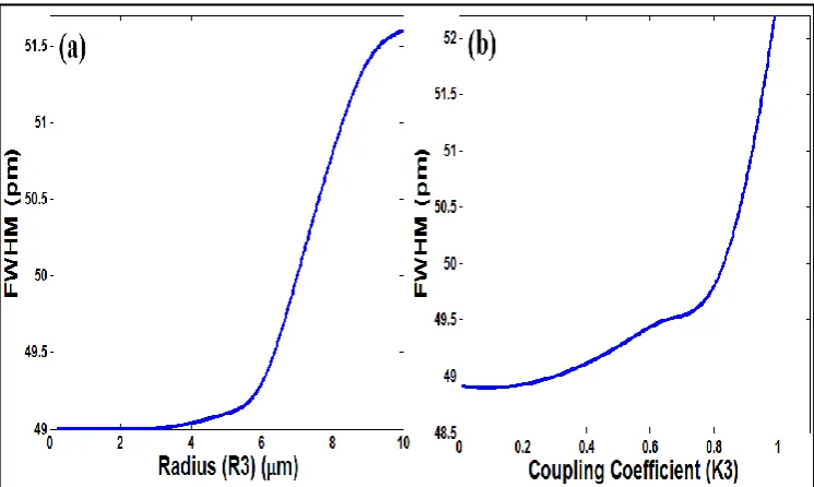
The variation of the FWHM versus the coupling coefficients (κ1) and (κ2) is shown in Figure 5. Thus increasing the
coupling coefficients leads to increase the FWHM. The variation of the FWHM versus the coupling coefficients (κ3)
and radius of the third ring resonator is shown in Figure 6. Here, the same concept is valid, thus increasing the variable parameters such as the ring radius and coupling coefficient of the three rings connected to the add/drop filter system causes the FWHM increased.To maximize the efficiency of the MRRs, the resonator bandwidth should be selected properly. This still allows for selection between a small, high-finesse resonator or a larger and proportionally lower-finesse resonator.
Figure 5. Simulation of FWHM, where (a): coupling coefficient (κ1) of the first ring varies, (b): coupling
coefficient (κ2) of the second ring varies.
Figure 6. Simulation of FWHM, where (a): radius of the third ring varies, (b): coupling coefficient of the third ring varies
Figure 7. FWHM and FSR, where (a): Add/Drop's radius (R) versus FWHM, (b): Add/Drop's radius (R) versus FSR
Using this method, the output power of the system can be simulated successfully. This system act as a passive filter system which can be used to split the input power and generate chaotic signals using suitable parameters of the system. Therefore input power of Gaussian beam can be sliced to smaller peaks as chaotic signals. The chaotic signals have many applications in optical communications.
CONCLUSION
The dependence of the chaotic signals on the radius of the ring resonator has been investigated. The output power of the system depends on the coupling coefficient, where higher coupling coefficient leads to generate pulses with lower output power, thus the system can be improved using smaller coupling coefficient. The series of MRRs are connected to an add/drop filter system to generate ultra-short soliton pulses. The soliton pulseswere generated using the proposed system, where ultra-short soliton pulse with FWHM of 50pmare obtained and analyzedregarding the variable parameter such as the radius and coupling coefficient of the rings.Optical channel filters with wide FSR (high selectivity) are required in such a system like DWDM in optical communication, where, the low finesse is a benefit for an optical transmitter system in which the system experiences uniform transmission along the fiber optics.
ACKNOWLEDGEMENTS
I. S. Amiri would like to acknowledge the financial support from University Malaya/MOHE under grant number UM.C/625/1/HIR/MOHE/SCI/29.
REFERENCES
De Vos K, Bartolozzi I, Schacht E, Bienstman P, Baets R (2007). Silicon-on-Insulator microring resonator for sensitive and label-free biosensing. Optics express 15(12): 7610-7615.
Dorfmüller J, Vogelgesang R, Weitz RT, Rockstuhl C, Etrich C, Pertsch T, Lederer F, Kern K (2009). Fabry-Pérot resonances in one-dimensional plasmonic nanostructures. Nano letters 9(6): 2372-2377.
Guarino A, Poberaj G, Rezzonico D, Degl'Innocenti D, Günter P (2007). Electro–optically tunable microring resonators in lithium niobate. Nature Photonics 1(7): 407-410.
Amiri IS, Alavi SE, Idrus SM, Supa'at ASM, Ali J, Yupapin PP (2014). W-Band OFDM Transmission for Radio-over-Fiber link Using Solitonic Millimeter Wave Generated by MRR. IEEE Journal of Quantum Electronics 50(8): 622 - 628.
Amiri IS, Alavi SE, SM Idrus, Nikoukar A, Ali J (2013). IEEE 802.15.3c WPAN Standard Using Millimeter Optical Soliton Pulse Generated By a Panda Ring Resonator. IEEE Photonics Journal 5(5): 7901912.
Nawrocka MS, Liu T, Wang X, Panepucci RR (2006). Tunable silicon microring resonator with wide free spectral range. Applied physics letters 89(7): 071110.
Rabus D, Hamacher GM (2001). MMI-coupled ring resonators in GaInAsP-InP. Photonics Technology Letters, IEEE 13(8): 812-814.
Alavi SE, Amiri IS, Idrus SM, Supa’at ASM, Ali J, Yupapin PP (2014). All Optical OFDM Generation for IEEE802.11a Based on Soliton Carriers Using MicroRing Resonators IEEE Photonics Journal 6(1).
Sridhar B (1998). Optical add-drop multiplexers for WDM optical communication systems, Google Patents.
Xu Q, Sandhu S, Povinelli ML, Shakya J, Fan S, Lipson M (2006). Experimental realization of an on-chip all-optical analogue to electromagnetically induced transparency. Physical review letters 96(12): 123901.
Yupapin P, Suwancharoen W (2007). Chaotic signal generation and cancellation using a micro ring resonator incorporating an optical add/drop multiplexer. Optics Communications 280(2): 343-350.
Accepted 19 September, 2014.
Citation: Amiri IS, Ahmad H, Zulkifli MZ (2014). Integrated ring resonator system analysis to Optimize the soliton transmission. International Research Journal of Nanoscience and Nanotechnology, 1(1): 002-007.
Copyright: © 2014 Amiri et al. This is an open-access article distributed under the terms of the Creative Commons Attribution License, which permits unrestricted use, distribution, and reproduction in any medium, provided the original author and source are cited.