Vol.8 (2018) No. 4
ISSN: 2088-5334
Experimental Study of Solar Module & Maximum Power Point
Tracking System under Controlled Temperature Conditions
Parvathy Rajendran
*, Howard Smith
# *School of Aerospace Engineering, Universiti Sains Malaysia, 14300 Nibong Tebal, Pulau Pinang, Malaysia E-mail: [email protected]
#
Aircraft Design Group, School of Engineering, Cranfield University, MK43 0AL Cranfield, England E-mail: [email protected]
Abstract— An experimental work has been designed to evaluate the performance of solar module thoroughly. This is crucial to
develop a solar module and maximum power point tracker (MPPT) system design for optimal operation of solar-powered unmanned aerial vehicle (UAV). The impact of temperature and solar irradiance intensity at various solar module angle investigated to study the effect of solar module power output of a moving UAV. Moreover, the effect of lamination on solar module and the benefit of MPPT for application of small solar-powered UAV are scrutinized. The results show that the optimum operating temperature for this solar module is approximately 45°C and solar power rises almost linearly along the solar module tilt angle. The laminated solar module has consistently loss 10% power compared to the non-laminated solar module. Besides, an additional 24% power can be obtained with the use of MPPT for small solar-powered UAV developed by Aircraft Design Group, Cranfield University.
Keywords— solar module; MPPT; solar-powered UAV; tilt angle; laminated solar; solar intensity
I. INTRODUCTION
Recently, there are lots of solar-powered UAV developed to accomplish the unlimited flight duration without refueling and polluting environment [1]-[8]. Moreover, the expanding number of ‘commercial of the shelf’ technologies including lightweight batteries, solar cells, and efficient electric motors indicate that electric or solar-augmented electric UAVs may offer potential. Furthermore, the availability of miniaturized sensors and other avionic components is starting to open up the possibility of designing useful air platforms that can be small and yet still perform a useful function.
The commercially available photovoltaic module technology, relevant for designing UAVs can be categorized as wafer-based silicon and thin film photovoltaic. Among these photovoltaic modules, the wafer-based silicon device dominates most of the market. This is mainly due to the better efficiency of wafer devices. However, there are many advantages to using thin-film modules, especially for a UAV.
However, current the solar cell performance itself is insufficient to achieve this target [9]-[13]. Although the manufacturer has defined the optimal operating temperature for solar cells, the performance of solar-powered UAVs in real flight defers due to changes in temperature and solar modules angles [12], [14], [15]. Moreover, the performance of mass-produced flexible solar cells may be inconsistent.
Besides, aircraft systems capabilities are pre-defined by their manufacturers, mass-produced parts, in general, have lower performances than a prototype/ laboratory tested parts. Therefore, it is crucial to determine these commercially available off the shelf products’ actual characteristic. This process helps to define the impact level of these parts performances to the final aircraft performances.
In order to evaluate the performance of solar module and MPPT thoroughly, an alternative low cost alternative experimental method has been designed. The 12 V solar modules tested in this experimental work were part of the solar module developed for small solar-powered UAV by Aircraft Design Group, Cranfield University, United Kingdom [16].
II. MATERIAL AND METHOD
The primary parameter that is evaluated in this experimental work is the power output from the solar module at various tilt angles and temperatures. Thus, identifying the optimum operating temperature and its corresponding tilt angle on the module performance for the UAV are essential to maximize its mission capabilities. In the following section, the details on the solar module and the experimental set-up did are elucidated.
A. Solar Module
The solar module used for this work is fabricated using 4 MP3-37 solar cell (Fig. 1) connected in series where each operates at 3.0 V and delivers 0.050 A current. Detail solar cell description is given in Table 1.
Fig. 1 The fabricated 12 V solar module
TABLEI
DETAIL SOLAR CELL SPECIFICATION
PowerFilm MP3-37 Power (W) 0.15 Voltage (V) 3 Capacity (Ahr) 0.05 Weight (g) 1.2 Length (mm) 37 Width (mm) 1.2 Thickness (mm) 0.2
This 12 V solar module is one of the 47 that have been packed in parallel to deliver a maximum current of 2.35 A to charge the custom-built LiPo battery pack in the solar-powered UAV (Fig. 2) developed by the Aircraft Design Group, Cranfield University, United Kingdom [16]. In total, when all 47 solar modules are connected in parallel, it will be able to supply at a maximum power of 28.2 W.
Fig. 2 Solar-powered UAV developed Aircraft Design Group, Cranfield University
B. MPPT
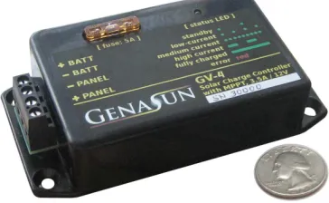
There are many MPPT available in the market ever since the global approach for greener renewable energy. While MPPTs market demand is not for mobile systems, only limited MPPT units, which are compact and lightweight, are available. The chosen MPPT for this case study is the Genasun GV-4 Li MPPT unit as shown in Fig. 3. This unit weighs 80 g.
Fig. 3 Genasun GV-4 Li MPPT
After all parts size and layout arrangement are estimated for the solar UAV, limited space was available. Therefore, the casing cover of this MPPT has been removed and repacked using the heat-shrink tube to prevent static charges damaging the internal circuit board. This has reduced the MPPT weight by 50% and up to a third of its size. The repacked MPPT right is given in Fig. 4.
A Schotty diode and a mini blade fuse have been installed in the between the batteries and solar modules. The chosen diode, 1N5820TSC prevents the solar modules drawing current up to 3A from the battery in the event of low or no solar power. Since the complete solar modules may only operate at a maximum current of 2.82A, this diode protects unwanted battery power usage well above the solar module capacity. Further on GV-4 Li MPPT specification is given in Table 2 below.
TABLEII DETAIL MPPTSPECIFICATIONS
Specifications For 3-cell Li-Poly Maximum Panel Power 45W
Maximum Current Limit 4A GV-4-Li-12.5v Float
Voltage 12.5V Battery System Voltage 8-18V Panel Voltage (Voc) 0-27V Self-Consumption (low
light) 0.125 mA (125 uA) Night Consumption 0.090 mA (90 uA) Efficiency 94% - 98% typical Tracking Efficiency 99% typical Operational
Temperatures -40 - 85 deg Celsius Size 4.3x2.2x0.9", 11x5.6x2.5cm Weight 2.8oz., 80g
Mounting Surface-Mountable Box with Mounting Flange
Connection 4-position plated brass screw-clamp terminal block for 12-24AWG wire
Features
Electronic Reverse Battery Protection Over-Temp. Protected w/ Current-Fold back
Automatic Recovery from Fault Conditions
LED Status and Charge Current Indicator
Reverse Protection of Solar Panel Input
Warranty Limited Lifetime
C. Experimental Setup
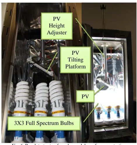
An experimental set up was designed to evaluate the performance of solar module at various tilt angles and controlled temperature environment. Thus, all experimental work was done using an environmental chamber as shown in Fig. 5 that requires liquid nitrogen. The liquid nitrogen has helped to maintain a constant temperature throughout the testing period. Fig. 6 illustrates the setup done for solar module performance simulation respectively.
In order to simulate consistent amount solar irradiance intensity, 32 W full spectrum bulbs are used. These bulbs are the capability of imitating 95% of the natural sunlight eliminating the cloud cover effect or expensive solar irradiance-simulating chamber. The solar module’s position from these bulbs can be adjusted (as shown in Fig. 4) in the
testing chamber to vary the amount of solar irradiance intensity by moving the module closer or further from these bulbs.
However, due to space constraint in the environmental chamber, only 9 bulbs were installed. As a result, the range of solar irradiance obtained from this setup is between 100W/m2 and 350W/m2. Therefore, in this experimental work, the solar irradiance intensity was simulated at an incremental of 50W/m2. A solar meter was used to measure the solar irradiance produced by the bulbs precisely. In addition, a high reflective foil has been used to increase the concentration of the emitted solar irradiance level from these bulbs.
Fig. 5 Environmental testing chamber with a liquid nitrogen tank
Fig. 6 Bench test setup for solar module performance testing
D. Solar Module Experimental Technique
The solar module is tested on temperatures ranging from -20°C to 60°C since this is the operating temperature range
PV
3X3 Full Spectrum Bulbs PV Tilting Platform PV
set by the manufacturer. In these tests, five surrounding temperatures six different solar irradiance levels and 7 solar irradiance angles were the conditions taken into consideration.
The adjustable feature of solar cells helps to vary the amount of irradiance on the top of the solar cell’s surface. In addition, a high reflective foil has been used to concentrate the solar irradiance of these bulbs. This helps to minimize the loss of irradiance and also reduces the number of bulbs required. In this occasion, the tilt angle is defined as the angle between the solar module plane and simulated solar irradiance.
Apart from these conditions, the chosen solar cells are tested 1) as it is, and 2) with solar film lamination. Thus, 420 combination tests were done to assess the solar cell. In addition, each of these tests will be repeated three times to ensure data precision.
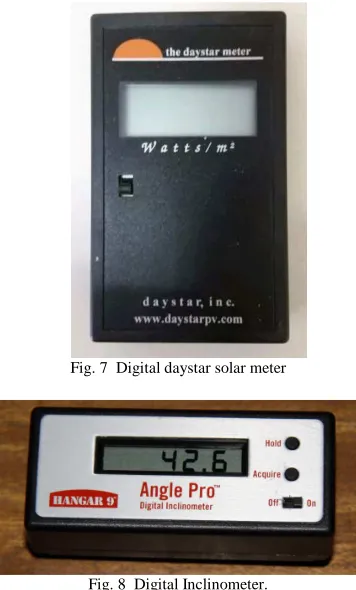
Here, a Digital Daystar solar meter shown in Fig. 7 has been used to measure the solar irradiance produced by these bulbs. Besides, a digital inclinometer as shown in Fig. 8 which is used to measure the solar module inclination angle in degree with an accuracy of one decimal point.
Fig. 7 Digital daystar solar meter
Fig. 8 Digital Inclinometer.
Also, the eagle tree system (ETS) has also been installed to measure other estimated parameters. The parameters recorded during these tests are the solar cell’s voltage, current, temperature and incidence angle, and the solar irradiance from the full spectrum bulbs installed in the testing chamber.
E. MPPT Experimental Technique
As for MMPT testing, the surrounding temperature and battery charging capacity are the two test conditions that have been set to determine its characteristics. However, there is a slight difference in the charging capacities range. Since
the solar module installed on the case study UAV only delivers a maximum of 3 amps, the charging capacity range has been limited to a maximum of 1.50C. Thus, 30 test combinations obtained, where five temperatures, 6 different charging capacities have been done.
A similar setup shown in Fig. 6 was done to evaluate the Genasun GV-4 Li MPPT’s performances. In these test, the liquid nitrogen-testing chamber, ETS, and a power supply are the only testing equipment used. The power supply replaces the solar module position to supply a constant current output through MPPT, which will then charge the battery packs. The logged data includes the MPPT’s output voltage, current and temperature, and power supply’s output voltage.
III.RESULTS AND DISCUSSION
A. Solar Module Testing
Power trend versus temperatures at various solar irradiances and solar module tilt angle of 90° for the non-laminated solar module and the non-laminated solar module is illustrated in Fig. 9 and 10 respectively. In general, the amount of power obtained from a non-laminated solar module is more than the laminated solar module.
Fig. 9 Power versus temperature at various solar irradiances at 90° solar angle of the non-laminated solar module
The power obtained by the non-laminated solar module with a solar irradiance of 350W/m2 at 25°C is 2.83mW while laminated solar module can only obtain 2.54mW for the same condition. The power loss by the laminated solar module is due to the reflective nature and transparent sheet place to cover the solar for weather protection.
Both types of solar module cannot function well when the temperature is below 0°C. The power gained is less than 1mW for both at this condition. The situation remains the same even when the solar irradiance increases. This is mainly because the electrons movement is affected by the surrounding temperature. As temperature increases, the power obtained will be higher until optimum temperature is reached.
The optimum temperature for both non-laminated and laminated solar module is roughly 45°C. The performance of the solar modules declines when the temperature is beyond the optimum point. The high internal resistance of the solar module when the temperature is high is the primary cause of the decrement of power output. Moreover, the increment of solar irradiance will only increase the power obtained by the solar modules regardless is non-laminated or laminated.
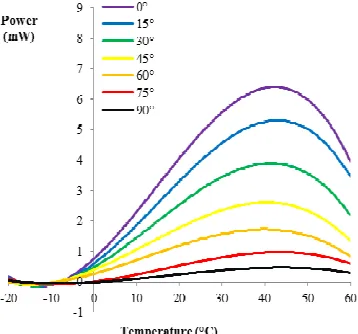
Fig. 11 Power versus temperature at a various solar angle at 350W/m2 of
the non-laminated solar module
Fig. 12 Power versus temperature at a various solar angle at 350W/m2 of
the non-laminated solar module
The actual solar module tilt angle for the UAV varies during flight. Thus, it is crucial to investigate the power gained at various tilt angles. Hence, the powers of
non-laminated and non-laminated solar modules at 350W/m2 of solar irradiance over temperatures at different tilt angles are shown in Fig. 11 and 12 respectively. The results show that the optimum temperature is still within 40°C to 45°C when the solar angle is varied.
The non-laminated and laminated solar modules are further compared with each other by plotting a graph on power versus solar irradiance at 25°C with 90° of solar angle as shown in Fig. 13. Since experimental setup could only achieve up to 350W/m2 of solar irradiance intensity, these results were extrapolated to 1350 W/m2 of solar irradiance intensity to forecast the maximum power obtainable at outer atmosphere.
The non-laminated solar module can deliver 0.925W of power with a solar irradiance of 1350W/m2 at 25°C. However, the amount of power is still less than the manufacturer’s data by 6% whereby the actual power is supposed to be 0.984W for the same condition. Furthermore, the power loss of 10% between laminated and non-laminated solar module is consistent throughout the tested results and in the forecasted data.
Fig. 13 Power versus solar irradiances at 90° solar angle at 25°C
Besides, the increment in tilt angle contributes to the increase in power obtained significantly for both non-laminated and non-laminated solar modules. At 25°C and 350W/m2 of solar irradiance, the trend for power versus solar module tilt angle plotted for both non-laminated and laminated solar modules as shown in Fig. 14. These data are essential to developing an energy-optimized path for solar-powered UAV.
Fig. 14 Power trend versus temperature at 350W/m2 solar irradiance at
25°C
B. MPPT Testing
Another part of the investigation done was on MPPT to evaluate the effectiveness of maximum power tracking capabilities for small solar-powered UAV. Since the amount of solar module’s nominal voltage and maximum current flow is 12 V and 2.82 A correspondingly, power supply was used to imitate the solar module power. The maximum current limit of the chosen MPPT is 4 A. Thus the test is conducted up to the 1.5 C charging rate which is equivalent to 3.9 A. This amount of current is within the limit of MPPT but is more than the maximum achievable current output from the solar module.
Fig. 15 illustrates the impact of power versus temperature while charging an 11.1 V and 2.6 Ah LiPo battery at different charging rate when MPPT is attached. The results clearly show that temperature has minimal effect on the MPPT’s performance and the power gained is almost constant over the temperature range. Hence, the effect of MPPT’s power consumption to the overall performance can be ignored when compared with non-MPPT system.
Fig. 15 MPPT incorporated solar module system; power trend versus temperature at a various charging rate
Fig. 16 illustrates the power delivered when charging this LiPo battery-overcharging rate at various temperatures with and without MPPT. The black dashed line in this figure shows the power obtained from a solar module without the use of MPPT. It is obvious that the power obtained is higher when an MPPT system is used together with the solar module. At 0.65 C charging rate, the power gained with the use of MPPT is 18.87 W instead of 15.21 W without MPPT.
Fig. 16 MPPT incorporated solar module system; power trend versus charging rate at various temperatures
The MPPT has self–consumption of around 1.5mW, but this value has a negligible effect on power obtained unless the charging rate is less than 0.0007 C. Moreover, this charging rate is only possible when the solar module delivers current at about 0.28mA. However, the efficiency of MPPT is reduced when the charging rate is beyond 1.45 C. This is due to the current flow rate is almost close to the MPPT’s maximum current limit. Therefore, the internal resistance of MPPT is increased drastically which lessens the MPPT’s efficiency.
Fortunately, the maximum achievable charging rate from a solar module is only 1.08 C approximately whereby 1.45 C charging rate is irrelevant to the developed solar-powered UAV. The solar UAV will obtain roughly 24% extra power with the use of MPPT when the solar module operates at 0.567 C nominal charging rate. An MPPT is proposed to maximize the solar output power used to charge battery packs for small solar-powered UAV.
IV.CONCLUSIONS
On the other hand, MPPT has minimal performance effect concerning temperature. Furthermore, the power consumption of MPPT has a negligible impact on the overall performance compared to non-MPPT system. In addition, an extra 24% power at peak can be obtained with the use of MPPT.
ACKNOWLEDGMENT
Universiti Sains Malaysia’s Short Term Grant No. 304/PAERO/60315002 supported this publication.
REFERENCES
[1] Jashnani S, Nada T, Ishfaq M, Khamker A, Shaholia P. Sizing and preliminary hardware testing of solar-powered UAV. The Egyptian Journal of Remote Sensing and Space Science. 2013;16(2):189-98. [2] Smith H, Rajendran P. Review of the elementary aspect of small
solar-powered electric unmanned aerial vehicles. Australian Journal of Basic and Applied Sciences. 2014;8(15):252-9.
[3] Gao X-Z, Hou Z-X, Guo Z, Fan R-F, Chen X-Q. The equivalence of gravitational potential and rechargeable battery for high-altitude long-endurance solar-powered aircraft on energy storage. Energy conversion and management. 2013;76:986-95.
[4] Gao X-Z, Hou Z-X, Guo Z, Liu J-X, Chen X-Q. Energy management strategy for solar-powered high-altitude long-endurance aircraft. Energy conversion and management. 2013;70:20-30.
[5] Rajendran P, Smith H, editors. Future trend analysis on the design and performance of solar-powered electric unmanned aerial vehicles. Advanced Materials Research; 2015: Trans Tech Publ.
[6] Kontogiannis SG, Ekaterinaris JA. Design, performance evaluation and optimization of a UAV. Aerospace science and technology. 2013;29(1):339-50.
[7] Zhu X, Guo Z, Hou Z. Solar-powered airplanes: A historical perspective and future challenges. Progress in Aerospace Sciences. 2014;71:36-53.
[8] Rajendran P, Smith H. Implications of longitude and latitude on the size of solar-powered UAV. Energy conversion and management. 2015;98:107-14.
[9] Devabhaktuni V, Alam M, Depuru SSSR, Green RC, Nims D, Near C. Solar energy: Trends and enabling technologies. Renewable and Sustainable Energy Reviews. 2013;19:555-64.
[10] Rajendran P, Smith H, bin Masral MH. Modeling and simulation of solar irradiance and daylight duration for a high-power-output solar module system. Applied Mechanics and Materials. 2014;629:475. [11] Salih SM, Salih FF, Hasan ML, Bedaiawi MY. Performance
evaluation of photovoltaic models based on a solar model tester. International Journal of Information Technology and Computer Science (IJITCS). 2012;4(7):1.
[12] Rajendran P, Masral MH, Kutty HA. Perpetual Solar-Powered Flight across Regions around the World for a Year-Long Operation. Aerospace. 2017;4(2):20.
[13] Rajendran P, Smith H. Modelling of solar irradiance and daylight duration for solar-powered UAV sizing. Energ Explor Exploit. 2016;34(2):235-43.
[14] Rajendran P, Smith H. Review of Solar and Battery Power System Development for Solar-Powered Electric Unmanned Aerial Vehicles. Advanced Materials Research. 2015;1125.
[15] Fazelpour F, Vafaeipour M, Rahbari O, Shirmohammadi R. Considerable parameters of using PV cells for solar-powered aircrafts. Renewable and Sustainable Energy Reviews. 2013;22:81-91. [16] Rajendran P, Smith H, editors. The development of a small solar