Influence of the Milling Strategy on the Durability of Forging
Tools
Pahole, I. ‒ Studenčnik, D. ‒ Gotlih, K. ‒ Ficko, M. ‒ Balič, J. Ivo Pahole1* ‒ Dejan Studenčnik2 ‒ Karl Gotlih1 ‒ Mirko Ficko1 ‒ Jože Balič1
1Faculty of Mechanical Engineering, University of Maribor, Slovenia 2Unior Nigbo Forging Co. LTD, China
The quality of a tool’s surface has a direct influence on the number of well-produced parts. For the machining of an active tool surface, two technological processes are used: electrical discharge machining and high-speed milling. These two processes are used when machining new tools and for the repairing of used forging tools. In both cases, the material has already been thermally treated, so it has to be used for hard milling. Practical experience shows that the milling strategy has a big influence on the durability of a forging tool. This paper shows the influence of the CNC machining direction during high-speed milling on the durability of the engraving within the forging tool. In some cases the correct milling strategy can increase the durability of the forging tool by about one third.
©2011 Journal of Mechanical Engineering. All rights reserved.
Keywords: forging tools, surface quality, high speed cutting, CNC milling
0 INTRODUCTION
Hot or cold-forging using forging tools enables us to approach to the product using one or more forging-operations. The engraving within the forging-tool is approximately a negative shape of the product although it is never completely equal to the negative of the product itself. It depends on the forging technology. The forming technology is directly responsible for the durability of the forging tool when forging. It is important to manage those factors that most influence the durability of the forming-tool. When manufacturing active surfaces, one of the more important influences is the roughness of the engraving surface. The requirements for the roughnesses of surfaces when forging are N6. It has been shown, however, that – in addition to the conditionally required measured roughness – it is also necessary also to take into consideration the direction and the type of final milling regarding the engraving with CNC, respectively HSC (high-speed cutting).
This paper shows the two flow-line milling with HSC of a forging tool for forging on a pneumatic hammer. It has been shown the flow-line milling is more appropriate for the engraving in comparison to closed/open line milling, and enables a higher duration of engraving from the forging-tool. Flow-line milling also has
advantages within the smaller dynamical loads on the forging machine, which influences the smaller roughnesses of the engraving surfaces [1].
The milling strategy of the forging tool active surfaces depends on the forged product. Certain guidelines are also given, which enable the user to influence the durability of the forging tool using appropriate technological operations at production or renewal of forging tools. An increase in the durability of forging-tools is one of the main research directions within forging.
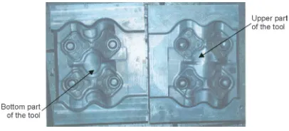
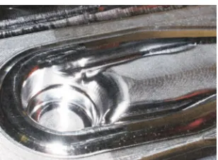
Fig. 1. Example of forging tool
1 DEPENDENCY OF MILLING STRATEGY AND TECHNOLOGICAL DEMANDS
by the term milling strategy. When working on conventional machines, this strategy did not normally take precedence because, in most cases, there were very simple possibilities for control. Nowadays, this is completely different on CNC machines because the controls enable various possibilities for tool-control within the workspace [2].
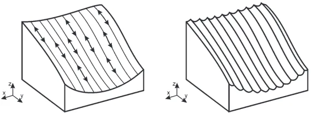
Whilst for rough-milling the success is measured by the amount of removed material within a time unit, for surface-milling the quality of the surface is the most important factor when measuring the effectiveness of the process. In rough-milling there are very few different shapes of toolpaths, because the milling strategy is determined by the cutting-parameters (velocity, feed velocity, cutting depth, step-over), which are manly dependent on the used tools, and the machine tool. During surface-milling, the toolpath is not as strongly determined regarding the capability of the machine, and the cutting tool, as it depends more on the surface quality. In addition to the quality of the surface as measured by the roughness, there are other surface properties that cannot only be described by the measurement of quality or roughness. These surface-properties are a consequence of the milling-strategy. One of these properties is the direction of the roughness, respectively the orientation of the scallop. The direction of the scallop depends on the direction of the trajectories (Fig. 2), while the height and shape of scallop depend on the shape of the milling tool, and the technological parameters.
The scallop arises, not just as a result of the moving tool, but also as a result of the feed-movement, and the low number of cutting edges [3] and [4]. The primary scallop follows
the direction of the tool, the secondary scallop is perpendicular to the direction of the tool’s movement [5]. In the case of a high-velocity of feed movement and low rotational speed the secondary scallop can exceed the height of the primary crests [3]. Special care must be taken concerning these crests, especially during HSC milling. Generally, the surface roughness during CNC milling, depends on [6]:
• The depth of cut. The depth of cut
influences surface quality in an indirect way. Increasing the depth of cut increases the cutting resistance and the amplitudes of any vibrations. The cutting temperature also rises. Therefore, it is expected that the surface quality will deteriorate.
• The feed-rate per cutter tooth. Experiments show that, as the feed-rate increases the surface roughness also increases [7]. In any case, using feed-rates under a certain limit does not yield any substantial improvement in surface quality.
• The cutting speed. An increase of cutting-speed generally improves surface quality. • Stepover of tool.
• The cutting-tool wear. The irregularities of the cutting-edge due to wear are reproduced on the machined surface. Apart from this, as tool-wear increases, other dynamic phenomena such as excessive vibrations will occur, further deteriorating the surface quality.
• The use of cutting-fluid. The cutting-fluid is generally advantageous in regard to surface roughness because it affects the cutting-process in three different ways.
Based on their experience, engineers can identify those successful strategies for individual shapes or characteristics of the surface, from the point of view of surface quality.
The more frequently used strategies for the treatment of free-surfaces are those strategies regarding surface treatment at z-levels and the strategy of parallel-passing, as in Fig. 2. The strategy of treatment at z-levels has, from the point of view of control and cutting, many advantages because it proceeds along the surface parallel to the x-y working surface. It is best suited for milling surfaces or parts of steep surfaces. The strategy of the treatment using parallel-passing is the projection of the trajectory on to the x-y surface in the shape of a parallel-passing. Although this passing is not defined by the inclination of the surface, the used toolpath lies in the direction of the surface’s inclination. The tool is moving “up and down” on the inclination. In most cases the milling goes in the downward direction of the inclination. This strategy is the best for the treatment of more gentle surfaces.
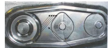
Although the more often used milling strategies are used as one for the steeper and another for gentler slopes, they can also be used for different shapes of surfaces. The two previously-mentioned strategies can also be used when it is technically and technologically better to mill the surface in different directions, as in the case of the material flowing within the forming tool, as shown in Fig. 5. In addition to these two strategies, there are many different strategies that can be used when milling for special requirements. Fig. 3 shows the use of directional material flow during a forging process for determining the direction of milling and the forming of a primary scallop.
The quality of the treated-surface, correspondingly the height of the scallop, can mostly be managed with cutting parameters, and the parameters of the strategy. The cutting parameters are set by the producers of the tools, the carbide inserts, and from experience. From a technological point of view it is best, if the CAM software supports the programming with respect to the heights of the deviations from the desired surface (the scallop height). The scallop height is defined for round milling tools and plane surfaces by:
h R= − (2R) −p ,
4 2 2
(1)
where R is the radius of the milling tool and p is the distance of passing the tool.
Generally, the surface, which is parallel to the desired surface and touches the peaks of the crests, [4], is defined by (Fig. 4):
PS,C(u,v)=P(u,v)+nh , (2)
where P(u,v) is the desired shape, n is the normal vector of the surface and h is the height of deviations (crests).
The surface treatment of a forging tool surface can be different according to the type of treatment. It is important to focus on the final treatment of the engraving. With respect to the surface milling when milling, we differentiate between:
a) line-milling, b) circular-milling, c) closed-line milling, and d) open-line milling.
often treated with line-milling, which can be open or closed [8].
Fig. 4. Description of the surface and the biggest deviations
According to the forging direction line milling can be oriented at different angles. During the process of forging, the biggest material flow is perpendicular to the forging direction. It is reasonable that the direction of the milling is oriented in the direction of the main material flow within the tool. The leftovers/scallop of the final treatment does not hinder the material-flow. Consequently, the wear is reduced. The real influence of the final direction treatment’s on the durability of the engraving can be stated:
• as the measurement of the engraving’s surface roughness, and
• as the tracking of the engraving’s durability during the forging process.
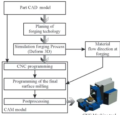
The direction of the material-flow within forging tool (Fig. 5) can be determined on the basis of the process’s technological plan for a particular product. The experiences of the tool-designers and engineers play an important role [9]. Computer programmes are a big support when designing forging tools on the basis of the finite elements method.
These are usually created computer programmes. The basic efficiencies of the software (DEFORM 3D) are:
– simulation of deformations and the heat-transfer for cold and hot forming,
– material flow analysis, filling of the engraving, – the forming-forces, stresses on the tool, shape of
the bean, diffusion process, – the hardness distribution, – analysis of the sintering,
– analysis of the cutting process (wear of tools, optimization of cutting parameters and the
shapes of the cutting tools, analysis of forces at cutting, analysis of the shapes of the cut-off ma-terial).
Fig. 5. Direction vectors of material flow in the forging tool
Fig. 6. Flow-chart of forging-tool production
2 TECHNOLOGICAL PARAMETERS OF THE FORGING PROCESS
The theoretical dependencies are quite well-known for the forging process. Therefore, it is logical to expect the same response for repeated conditions.
The coincidence of gluing the part to the tool can appear along with thickness changes and cracks appear. It can be concluded that non-influential factors are known. In spite of well-known accesses to the technology of forging, the experiences of the people who work in this field play an important role.
For forging parameters the interdependency of the parameters is important. The connections may be found within the parameters. Therefore, for any change of thickness ds on the press holds:
ds = 1 / ( k · dF) , (3) where ds is a change of the thickness, dF change of the forming force and k the stiffness of the press.
The reasons for changing the thickness and the process of changing, can be split (Fig. 7): • direct influences (technological influences of
the first order), and
• indirect influences (physical process quantities of the second and higher orders).
There are some estimations that there are at least ten process parameters that must be controlled for mastering the process.
3 RESULTS AND CONCLUSION
An experiment was prepared for the forging tool of an equal part. The surface milling of the tool surface was carried out using the following strategies:
• line-milling under an angle of 45° (example 1), Fig. 8, and
• closed-line milling (example 2), Fig. 9.
Fig. 8. The engraving is treated with line-treatment under an angle of 45˚ [1] (example 1)
Both tools were used for forging, with the same forging parameters. The results of the experiment are shown in Table 1. The results of this experiment have shown that line-milling gives better results. The change in milling strategy resulted in an approximately 30% longer duration of the forging tool.
Fig. 9. The engraving was treated with closed-line treatment [1] (example 2)
Table 1. Comparison of the experimental results
Roughness parameter
The tool was milled with
line-treatment at an angle of 45º (example 1)
The tool was milled with closed-line treatment (example 2)
Ra [mm] 0.78 0.86
Rz [mm] 4.78 6.02
Rmax [mm] 5.67 7.94
Number of produced
parts 28,784 20,148
The results of this experiment clearly show the influence of milling-strategy on its durability when applied to the active surface of a forging tool. It is favourable to use such a milling strategy that has toolpaths following the flow of the material during the forging process. Although the results are very promising, it should be noted that the research is incomplete, as yet. In the future we are planning to research the connections between various milling-parameters and milling-strategies, on forging tool durability.
4 REFERENCES
[1] Studencnik, D. (2004). Meaning and influence of different method renovation forging tools to abstinence of forging tools. Specialist thesis. Faculty of Mechanical engineering, University of Maribor.
[2] Kramar, D., Kopač, J. (2009). High pressure cooling in the machining of hard to machine materials. Strojniški vestnik – Journal of Mechanical Engineering, vol. 55, no. 11, p. 685-694.
[3] Chen, J.S., Huang, Y.K., Chen, M.S. (2005). A study of the surface scallop generating mechanism in the ball-end milling process. International Journal of Machine Tools and Manufacture, vol. 45, no 9, p. 1077-1084, DOI:10.1016/j.ijmachtools.2004.11.019. [4] Feng, H.Y., Li, H. (2002). Constant
scallop-height tool path generation for three-axis sculptured surface machining.
Computer-Aided Design, vol. 34, p. 647-654,
DOI:10.1016/S0010-4485(01)00136-1. [5] Chen, J.-S., Huang, Y.-K., Chen, M.-S.
(2005). A study of the surface scallop generating mechanism in the ball-end milling process. International Journal of Machine Tools and Manufacture, vol. 45, no. 9, p. 1077-1084, DOI:10.1016/j. ijmachtools.2004.11.019.
[6] Benardos, P.G., Vosniakos, G.C. (2002). Prediction of surface roughness in CNC face milling using neural networks and Taguchi’s design of experiments. Robotics and Computer-Integrated Manufacturing, vol. 18, no. 5-6, p. 343-354, DOI:10.1016/S0736-5845(02)00005-4.
[7] Kaczmarek, J. (1983). Principles of machining by cutting, abrasion and erosion. Peter Peregrinus, London.
[8] Klancnik, S., Senveter, J. (2010). Computer based work piece detection on cnc milling machine tools using optical camera and neural networks. Advances in Production Engineering & Management, vol. 5, no. 1, p. 59-68.
[9] Stupan, J., Potrc, I. (2000). Computer simulation forging processes. Strojniški vestnik – Journal of Mechanical Engineering, vol. 46, no. 9. p. 641-647.
[10] Kecelj, B., Kopač, J., Kampuš, Z., Kuzman, K. (2004). Speciality of HSC in manufacturing of forging dies. Journal of Materials Processing Technology, vol. 157-158, p. 536-542, DOI: 10.1016/j.jmatprotec.2004.07.112.