Loading Path Determination for Tube Hydroforming Process
of Automotive Component Using APDL
E. Masoumi Khalil Abad1, A. Ghazanfari2, R. Hashemi3
1-PhD, Mechanical Engineering Department, McGill University, Montreal, Quebec, Canada. 2-PhD student, Mechanical Engineering Department, Sharif University of Technology, Tehran, Iran.3- Assistant professor, School of Mechanical Engineering, Iran University of Science and Technology, Tehran, Iran;
Abstract
In this study, an extended stress-based forming limit diagram (FLD) for prediction of necking based on the Marciniak and Kucznski (M-K) model is represented and applied in tube hydroforming. The bulge forming of a straight tube is simulated by finite element method and verified with published experimental data. This adaptive simulation technique is based on the ability to detect the onset and growth of defects (e.g., bursting and wrinkling) and to promptly readjust the loading paths. Thus, a suitable load path is determined by applying Adaptive Simulation Method in ANSYS Parametric Design Language (APDL).
Keywords: forming; finite element simulation; bursting
1. Introduction
Hydroforming processes have become popular in recent years, due to the increasing demands for lightweight parts in various fields, such as bicycle, automotive, aircraft and aerospace industries. This technology is relatively new as compared with rolling, forging or stamping, therefore there is not much knowledge available for the product or process designers. Comparing to conventional manufacturing via stamping and welding, tube (THF) and sheet (SHF) hydroforming offers several advantages, such as decrease in work-piece cost, tool cost and product weight, improvement of structural stability and increase of the strength and stiffness of the formed parts, more uniform thickness distribution, fewer secondary operations, etc [1-2].
In the last few years, the demand for weight reduction in modern vehicle construction has led to an increase in the application of hydroforming processes for the manufacture of automotive lightweight components made from steel or aluminum. It results from improvements in stiffness and crash behavior due to the reduction of welding seams, and with reduced assembly costs. Currently, use of aluminum alloy which is light weight material is increasing. Extruded aluminum profiles have been used for automobile frame parts [3] to get higher stiffness and light weight, Figure 1. Many progresses have been made in forming of square sectioned profile by stretch bending and hydroforming [3].
The use of lightweight materials such as aluminum and magnesium can reduce the weight of passenger vehicles up to 40–75% by replacing ferrous auto body structures and body panels [3]. It was reported that a 10% weight reduction in an average auto-motive body could improve the fuel efficiency by 6–8% [3]. However, the cost for the lightweight materials is estimated to be higher than that of the mild steel structures because of the raw material price and the production costs with the existing manufacturing technologies. For aluminum alloys, the cost increases up to 30–100% are expected while it is forecast to be around 50–150% for the magnesium alloys [3]. On the other hand, since 80% of the total energy consumption throughout the life cycle of an automobile occurs during the utilization (driving) period, the use of lightweight parts is still seen as a prominent, long-term and cost effective response to the fuel efficiency and the emission reduction demands. Considerable mass savings are possible through eliminating the flanges required for welding and using thinner steel. In spite of that, stiffness is still maintained and the discontinuous spot-welded joints are eliminated [3].
Failures such as buckling and necking could occur in the tube hydroforming process. The causes of such defects are mainly incorrect loading conditions in applying the fluid pressure and axial feeding simultaneously.
556 Loading Path Determination for Tube Hydroforming ……
Fig1.Part of the sub-frame (a), photographs of forming of the extruded profile: bending (b), pressing (c), hydroforming (d) [3]
Since bursting in tube hydroforming process is a consequence of necking, prediction of necking initiation is an important issue before designing the details of the processes [4].
Strano et al. [5] proposed the adaptive simulation concept as an effective finite element method (FEM) approach to select a feasible tube hydroforming loading path with a minimum number of simulation runs or even with a single run. This technique is based on the ability to detect the onset and growth of defects (buckling, bursting and wrinkling) and to readjust the loading paths promptly. The detection and quantitative evaluation of wrinkles play a key role in implementation of the adaptive simulation. A new geometrical wrinkle indicator is introduced and evaluated with numerical and experimental evidence. The proposed wrinkle indicator is computationally inexpensive, suitable for many die shapes and sensitive to different kinds of wrinkles.
A classification of tube hydroforming processes based on sensitivity to loading parameters is suggested in [6]. Gao et al. [6] analyzed the characteristics of the classification in terms of failure mode, dominant loading parameters and their working windows. It is concluded that the so-called pressure dominant tube hydroforming process is the most difficult process for both simulation in FEA and practical operation in real manufacturing situation. Adaptive FEM simulation strategies are mostly needed to effectively determine the optimum loading path for pressure dominant tube hydroforming process.
The effect of strain path on the forming limit diagrams (FLDs) were examined by applying various bilinear strain paths (non-proportional loading histories) and it was concluded that the FLDs are strain path dependent (e.g. see [7] and [8]). Therefore,
they are not valid for formability evaluation of sheet metal forming processes undergoing non-proportional loading paths. To obtain a criterion with less strain path-dependency, a stress-based FLD or forming limit stress diagram (FLSD) was presented and implemented to detect necking [9]. In prediction of the sheet metal strain and stress limits, plane stress state is generally presumed. However, this hypothesis is only valid for processes with negligible out of plane stresses such as an open die stamping. It is reported that the sheet metal limit strains increase when the through-thickness compressive normal stress increases [10, 11].
Recently, Simha et al. [12] presented an extended stress-based FLD that could be used to predict the onset of necking in sheet metals loaded under non-proportional load paths, as well as under three-dimensional stress states. They transformed the conventional strain-based FLC into the stress-based FLD developed by Stoughton [7]. Then, they converted the obtained diagram into the extended stress-based FLD, which was characterized by the two invariants: mean stress and equivalent stress. Assuming that the stress states at the onset of necking under plane stress loading were equivalent to those under three-dimensional loading, the extended stress-based FLD was used in conjunction with finite element computations to predict the onset of necking during tubular hydroforming. Hydroforming of straight and pre-bent tubes of EN-AW 5018 aluminum alloy and DP 600 steel were considered. Experiments carried out with these geometries and alloys were described and modeled using finite element computations. These computations, in conjunction with the extended stress-based FLD, allowed quantitative predictions of necking pressures; and these predictions were found to agree to within
E. Masoumi Khalil Abad, A. Ghazanfari and R. Hashemi 557
10% of the experimentally obtained necking pressures. The computations also provided a prediction of final failure location with remarkable accuracy. In some cases, the predictions using the extended stress-based FLD showed some discrepancies when compared with the experimental results, and the paper addressed potential causes for these discrepancies.
In this work, the extended stress-based forming limit diagram is used to predict necking. The methodology for computation of the extended stress-based FLD was based on the modified M-K model. The suitable load path for bulge forming of straight tube was determined by applying adaptive simulation method in ANSYS Parametric Design Language (APDL).
2. Review of Computations
In this article, computations of tube material limit stresses are based on the modified M-K theory. In this method, it is assumed that there is a narrow groove in the sheet surface. Thus, the tube material is composed of a safe area (A) and a groove (B). This groove leads to localized necking in the tube material. Imposing of stress components at rolling and transverse directions in the safe area causes the progression of strain increments in both the safe and the groove areas (see Figure 2).
The computations in this work are based on the works of Assempour et al. [10] and Assempour et al. [11]. More explanations and detailed procedure of tube material strain and stress limits computations could be found in these references.
Yield Function and Hardening Law
(1) Based on general form of Hill’s quadratic yield criterion [13], the equivalent stress is given as
follows: where are coefficients of Hill’s 1948 yield function [13]. Assuming the existence of planar isotropy, the yield criterion can be specified as follows [13]:
(2)
For sheet metals, the r-values are usually obtained for three various directions of in-plane loading (e.g.,
to the rolling direction) and the normal
R-value is taken to be the average (e.g.
).A simplified hardening law (Power law relation) [20] is given as follows:
(3)
where denotes the effective stress, are the pre-strain and the effective strain respectively, is the strain hardening exponent, K is the strength constant, denotes the effective strain rate and m is the strain-rate sensitivity exponent.
3. Extended Stress-based FLD
As mentioned earlier, the FLDs are strain path dependent and cannot be applied to analyze tube hydroforming process under non-linear strain paths. Recently, the extended stress-based FLD was presented in [12] and it was reported that this diagram is much more strain path independent than the conventional FLD.
Fig2.Schematic diagram of the M-K model.
, ,
F G H
( ) ( ) ( )
1
2 2 2 2
2 3 3 1 1 2
3
2 [2 ]
y
r r
σ σ σ σ σ σ
σ
− + − + −
=
+
0 , 45 , 90° °
°
0 24 5 9 0
4
r r r
r= + +
Y
σ ε0,ε
n
ε&
( )2 ( )2 ( )2 1 2
_
2 3 3 1 1 2
3 2
y
F G H
F G H
σ σ σ σ σ σ
σ
− + − + −
=
+ +
(
0)
( )
m n Y K
σ = ε +ε ε&
558 Loading Path Determination for Tube Hydroforming ……
Moreover, it was assumed that the formability curve in stress space is not affected by a compressive
, where acted in the through-thickness direction. This assumption is adopted in the present work as well.
The extended stress-based FLD is constructed based on effective stresses (equivalent stresses) versus mean stresses at the onset of localized necking [12]. The equivalent stress was obtained using Hill’s yield criterion [13] (equations 1 and 2) and the mean stress is calculated as follows:
(4)
Results and Discussions
The adaptive simulation is an approach to obtain the load path with minimum defects considering the neck formations and wrinkling in tube hydroforming process [14, 15]. Applying ANSYS LS-DYNA and ANSYS Parametric Design Language (APDL), an adaptive simulation was carried out. The general algorithm of adaptive simulation method can be seen in Figure 3. A wrinkle predictor and a necking indicator are two essential aspects in any adaptive simulation design system.
An indicator is required for optimization of the
Process concerning wrinkle formation [15]. In the present article, based on the die geometry, the slope wrinkling indicator was used. Considering an axial line on the tube, once the line slope at a particular point changes its sign, there is a wrinkle creation potential at that point. More explanations could be found about this phenomenon in reference [15]. The proposed extended forming limit stress diagram approach was adopted for evaluation of forming severity and occurrence of the necking phenomenon. The extended forming limit stress diagram used in this work reduces the sensitivity of the limit diagram to the strain path in the bulging process.
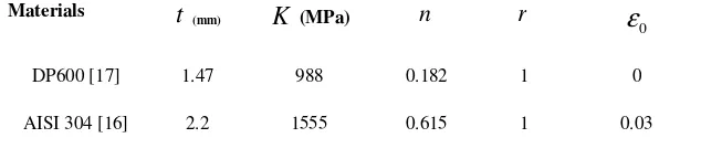
As a case study, an adaptive simulation method was implemented in APDL to determine suitable load path for tube hydroforming. Using this load path, suitable forming process without bursting and wrinkling failures was obtained. The computed extended forming limit stress diagram was utilized as a criterion for necking prediction. Tool and tube models were made in ANSYS LS-DYNA. A view of tube and die is shown in Figure 4. The tool was modeled as a rigid body. The tube material was transversely anisotropic elastic-plastic. Tables 1 and 2 demonstrate the geometrical parameters and mechanical properties used in this example. The coulomb friction coefficient of 0.05 was considered in the simulation.
Table 1: Die Geometry of Models.
Materials OD1
) (mm
2
OD ) (mm
1
L
) (mm
2
L
) (mm
3
L
) (mm
1
R
) (mm
2
R
) (mm
AISI 304 [16] 48.6 64 120 25 150 3.4 7.1
DP600 [17] 60 145 50 0 95 12.5 10
Table 2: Mechanical Properties of Tube.
(MPa)
(mm)
Materials
0 1
0.182 988
1.47 DP600 [17]
0.03 1
0.615 1555
2.2 AISI 304 [16]
3
σ σ3
1 2 3
3
hyd
σ σ σ
σ = + +
0
ε
r
n
K
t
E. Masoumi Khalil Abad, A. Ghazanfari and R. Hashemi 559
W r in k lin g in d ic a to r
B u rs tin g in d ic a to r
W rin k lin g Y e s B u rs tin g
E x it
G e o m e try a n d m e s h in g
B u rstin g
P re s = p re s + d p d is p = d is p
D is p = dis p + d d P re s = pre s
Y e s N o
s olv e
N o
P re s = p re s + d p d isp = d isp N o
In itia l loa d in g a n d s o lv in g
G e ttin g n e c es s a ry d a ta
Fig3.The general algorithm of adaptive simulation method
Fig4.The geometry of die and tube in bulge hydroforming.
The experimental load path in reference [17], shown in Figure 5, was applied to verify the current finite element model for AISI 304. The result is shown in Figure 6. As the results show, good agreement with experimental data has been achieved. Therefore, the finite element model can be used with adaptive simulation to obtain suitable load path.
Figure 7 demonstrates the load path obtained from adaptive simulation for tube material DP600
(HG:Z140) [17]. In this system, initially, the pressure and axial end feed are increased by small amounts. Then, the pressure remains constant and only the axial feed is increased. This process continues until wrinkling occurs. To prevent the wrinkling, the pressure and axial end feed are increased simultaneously in a linear path. As thinning occurs in the bulging zone, the slope of the load path is decreased and more material is fed into the bulging
560 Loading Path Determination for Tube Hydroforming ……
area. This procedure continues until reaching the necking condition. The extended stress path and extended forming limit stress diagram for material model DP600 (HG:Z140) are shown in Figure 8. Inhomogeneous factor is assumed 0.98. As can be seen in this figure, the process is stopped when the stress path crosses the extended forming limit stress diagram. The distribution of Von-Mises stress in deformed tube and thickness distribution along the
tube are shown in Figures 9 and 10. As could be seen, the minimum thickness at bulging zone is not very critical and no wrinkling occurred in the deformed tube; therefore, adaptive simulation method could provide the correct load path successfully.
Verification of the present load path by performing experiments is an issue to be considered in the future. Nevertheless, the present results show a qualitative agreement with experiments (e.g., see [14-17]).
Fig5.The load path [27] used for verification of the current FE model (for AISI 304 tube material)
Fig6.Comparison of tube wall thinning between the current simulation and experimental data [27] for AISI 304. 0
2 4 6 8 10 12 14 16 18 20
-50 50 150 250
E
n
d
F
e
e
d
(
m
m
)
Pressure (MPa)
Load path
-4 -2 0 2 4 6 8 10 12 14
0 0.1 0.2 0.3
T
u
b
e
w
a
ll
t
h
in
in
g
(
%
)
Longitudinal length (m)
FEM Experiment
0 5 10 15 20 25 30 35 40 45
-0.1 0.1 0.3 0.5
P
re
s
s
u
e
r
(M
P
a
)
Axial end feed (cm)
Load path
E. Masoumi Khalil Abad, A. Ghazanfari and R. Hashemi 561
Fig7.Load path determined by adaptive simulation method (present study), tube material DP600 (HG: Z140).
Fig8.Obtained extended stress path for bulge point in the present study, tube material DP600 (HG:Z140)
and inhomogeneous factor ( ) is assumed 0.98.
Fig9.Von-Mises Stress distribution in tube after free bulging (present work), tube material DP600 (HG:Z140).
Fig10. Thickness distribution along axial line (present work), tube material DP600 (HG: Z140).
f
0 0.0002 0.0004 0.0006 0.0008 0.001 0.0012 0.0014 0.0016
0 0.05 0.1 0.15 0.2
T
u
b
e
t
h
ic
k
n
e
s
s
(
m
)
Distance along one axial line (m) Thickness along axial line
562 Loading Path Determination for Tube Hydroforming ……
4. Conclusions
In this paper, the M-K theory was employed for prediction of the extended stress-based FLD. The extended stress-based FLD could be used to predict the onset of necking in sheet metal loaded under non-proportional load paths, as well as under three-dimensional stress states. The obtained extended stress-based FLD for tube material DP600 (HG:Z140) was applied to achieve the suitable load path in tube hydroforming process. An adaptive simulation can be used to obtain suitable load path with high formability in tube hydroforming.
References
[1]. P. Ray, B.J. Mac Donald, Experimental study and finite element analysis of simple X-shape and T-branch tube hydroforming processes, Int. J. Mechanical Sciences, 47; 1498-1518, 2005. [2]. Ch Hartl,. Research and advances in
fundamentals and industrial applications of hydroforming, J. Mater. Proc. Tech., 167 (2-3); 383–392, 2005.
[3]. A. Kocanda, H. Sadlowska, Automotive component development by means of hydroforming, Archives of Civil and Mechanical Engineering, 3; 55–72, 2008. [4]. J Kim,., Y. W. Kim, , B. S. Kang, and S. M.
Hwan, Finite element analysis for bursting failure prediction in bulge forming of a seamed tube, Finite Elements in Analysis and Design, 40; 953–966, 2004.
[5]. M. Strano, S. Jirathearanat, T.Altan, Adaptive FEM Simulation for Tube Hydroforming: a Geometry-Based Approach for Wrinkle Detection, CIRP Annals - Manufacturing Technology, Volume 50, Issue 1, 2001, Pages 185-190.
[6]. L. Gao, S. Motsch, M. Strano, Classification and analysis of tube hydroforming processes with respect to adaptive FEM simulations, Journal of Materials Processing Technology, Volume 129, Issues 1-3, 11 October 2002, Pages 261-267.
[7]. T.B. Stoughton, A general forming limit criterion for sheet metal forming, Int. J. Mech. Sci., 42 (1); 1–27, 2000.
[8]. T.B. Stoughton, X Zhu, Review of theoretical models of the strain-based FLD and their relevance to the stress based FLD, Int. J. Plast., 20 (8-9); 1463–1486, 2004.
[9]. G. Xu, K.J. Weinmann, A New Approach to Predicting Forming Limits of Steel Sheet,
Journal of Manufacturing Processes, Volume 2, Issue 3, 2000, Pages 158–166.
[10].A. Assempour, H. Khakpour, R. Hashemi, Forming limit diagrams with the existence of through-thickness normal stress. Computational Materials Science, Volume 48, Issue 3; 504-508, 2010.
[11].A. Assempour, R. Hashemi, K. Abrinia, M. Ganjiani and E. Masoumi, A methodology for prediction of forming limit stress diagrams considering the strain path effect, Comput. Mater. Sci. Volume 45, Issue 2, April 2009, Pages 195–204.
[12].C. H. M. Simha, J. Gholipour, A. Bardelcik and M. J. Worswick, Prediction of Necking in Tubular Hydroforming Using an Extended Stress-Based Forming Limit Curve, Transaction of the ASME, Journal of Engineering Materials and Technology, 2007; 129(1): 36-48.
[13].R. Hill, A theory of the yielding and plastic flow of anisotropic metals. Proc R Soc Lond A , 1948; 193:281–297.
[14].A. Aydemir, J.H.P. de Vree, W.A.M. Brekelmans, M.G.D. Geers, W.H. Sillekens, and R.J. Werkhoven, An adaptive simulation approach designed for tube hydroforming processes, J. Mater. Proc. Tech., 159 (3); 303– 310, 2005.
[15].M. Strano, S. Jirathearanat, S.Guang Shr, and T. Altan, Virtual process development in tube hydroforming, J. Mater. Proc. Tech., 146 (1); 130–136, 2004.
[16].Y. Aue-U-Lan, G. Ngaile, and T. Altan, Optimizing tube hydroforming using process simulation and experimental verification, J. Mater. Proc. Tech., 146 (1); 137-143, 2004. [17].N. Asnafi, A. Skogsga°rdh, Theoretical and
experimental analysis of stroke-controlled tube Hydroforming. Materials Science and Engineering A 2000; 279 (1-2):95–110.
E. Masoumi Khalil Abad, A. Ghazanfari and R. Hashemi 563
Appendix I: List of Symbols
Inhomogeneous factor , ,
F G H Coefficients of Hill’s 1948 yield function
Material constants Normal anisotropy factor
Ratios of transverse to through- thickness strains under uniaxial tension at 0, 45 and 90°to the rolling direction
Material thickness
Ratio of stresses along the strain path
Rate of effective plastic strain Effective plastic strain
Effective plastic strain increment Strain increment tensor
Strain increments in the material coordinates
1, 2, 3
σ σ σ Stress components in the material coordinates
Y
σ Effective stress obtained from hardening law
y
σ Effective stress obtained from yield function
hyd
σ
Mean stressf
0
, ,
K nε
r
0,45,90
r r r
t
α
ε
&
ε
ε
d
d
ε
3 2
1, ε , ε
ε d d
d