held at Saskatoon, Sask. June 18-20, p. C -6 -1-16. 1974.
MASTER COPY
AUTOMATIC CONTROLS FOR SURFACE IRRIGATION SYSTEMS!"
By
Allan S. Humpherys-I ABSTRACT
Automatic irrigation controls, such as gates, checks, valves, timers, soil moisture sensors and related devices, are described. These increase worker productivity and give better control of farm irrigation water. Most semi-automatic irrigation systems use mechanical timers to control irrigation and its duration, whereas automatic systems use sensors and programmed timers. Automatic and semi-automatic gates and checks are used in open channel systems to divert water through different kinds of openings. Low pressure valves and controls are being developed and tested for automating gated pipe systems.
INTRODUCTION
Irrigation usually requires the uniform distribution of 2.5 to 15 cm (1 to 6 in.) of water over a farm field at 3-to 20-day intervals to supply the moisture needs of a growing crop. With surface irrigation, water is applied
in large or small furrows or the soil surface is flooded within areas con-fined by low dikes. The size and shape of irrigated fields vary, depending' on the soils and field topography. Traditionally, irrigation has been an undesirable chore requiring much labor. The labor required and the water-use efficiency attainable depend, in part, on the on-farm irrigation facili-ties. The initial cost of these facilities at current prices must not exceed about $500-$1,250 per ha ($200-$500 per acre) for irrigated farms to remain competitive in producing food and fiber. In the past, extra labor and water were commonly used to minimize the investment in irrigation facilities. In recent years, because of the scarcity and high cost of labor, there has been a tendency to sacrifice good water control and substitute fertilizer for labor inputs where water and fertilizer were plentiful and inexpensive. These practices generally have resulted in relatively low irrigation
effi-ciencies.
Either additional labor or mechanization and automatic controls are needed to increase irrigation efficiency on most well-managed farms. Irrigation is one of the last farm operations considered for automation. Surface irri-gation in particular has not received the impetus of commercial development that sprinkler irrigation and other types of farm mechanization have re-ceived. Actually, because the surface irrigated acreage is larger, surface - irrigation equipment may have a greater potential market than sprinkler
equipment. Automatic irrigation controls can increase worker productivity 1I Contribution from the Western Region, Agricultural Research Service, USDA; University of Idaho College of Agriculture Research and Extension Center, Kimberly, cooperating.
2.1 Agricultural Engineer, Snake River Conservation Research Center,
-2-and may be the most feasible way to achieve better water control without in-creasing labor input. Increased demands for food and fiber may require that
irrigators use their water supply more efficiently to increase production
per unit volume of irrigation water diverted. Also, water quality control regulations will require better water control to decrease irrigation-related
pollution. Better water control facilities can decrease runoff and the
amount of sediment leaving an irrigated area.
Automatic controls for surface irrigation consist of a combination of gates,
structures, valves, timers, soil moisture sensors and other devices to auto-matically divert water to an agricultural field and distribute it
uniform-ly in the proper amount and at the proper time to replenish soil water used by a growing crop. These controls may be semi-automatic or fully automa-tic, depending on their method of operation. Some parts of a system may be semi-automatic or manual, while others are automatic. The water supply
and delivery system often determines the kind of controls needed.
Semi-automatic systems and controls normally cost less and are simpler than
automatic controls, but require some manual attention at each irrigation.
Most semi-automatic systems use mechanical timers or electric or hydraulic
devices to activate control structures at a predetermined time. The
irri-gator usually determines when to begin irrigation and its duration, and
manually resets, or returns the devices to their original positions or moves them from one location to another before the next irrigation.
Automatic controls are often more complex and do not require the operator to perform some of the manual functions required for semi-automatic con-trols. Automatic systems normally operate without attention from the opera-tor other than for periodic inspections and routine maintenance. However, the irrigator often determines when and for how long to irrigate, turns water
into the system, and/or starts programmed controllers, before the automated
portions of the system function. Fully automatic systems may have sensors, such as tensiometers or electrical resistance blocks, to indicate the need for irrigation. These activate electrical controls when soil water is de-pleted to predetermined levels. Meteorological data can also be used to predict when to irrigate, or the output from a small computer can be used to begin irrigation. Water is then diverted into the farm distribution
channels, and the irrigation is completed without operator intervention.
Irrigation duration may be controlled by programmed timers, soil moisture sensors, or surface-water sensors. Most fully automatic systems require a
water supply available on demand, such as from wells or farm reservoirs.
However, most farm systems do not have the flexibility required for complete automation.
CONTROLLERS AND SENSORS
The farmer may determine when to irrigate and the amount or duration of irrigation and set time controllers accordingly, or he may use soil water sensors. He may use computers to schedule when to irrigate and indicate how much water to apply, based on climate-crop-soil data. Devices that
irrigation can then proceed automatically from one set to another, utilizing one of the various timing methods.
Mechanical Timers
After water is diverted to the system, timers activate structures, valves, or other devices at predetermined times to either divert water on or off a field or to divert it from one portion of a farm to another. The timer, usually mounted on or near the water control structure, activates the struc-ture mechanically or electrically. Semi-automatic irrigation timers must be dependable. They should be corrosion resistant and well protected from moisture and dust. They should have a built-in trigger or trip from which a gate latch, electrical switch, or other tripping mechanism can be operated. Timers are usually set according to the required duration of a given irri-gation, rather than by the time of day. A minimum time capability of 24 hours is preferred; however, 12-hour timers are commonly used. Timers should have an escapement start-stop feature, so that they can be preset, but do not start until activated by a float. Thus, the total time that a group of
timers and their associated structures can be programmed may range from one day to several days, depending upon the number of timers used, because the timers operate in series with only one unit running at a time.
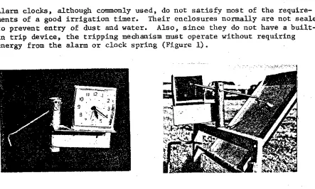
Alarm clocks, although commonly used, do not satisfy most of the require-ments of a good irrigation timer. Their enclosures normally are not sealed
to prevent entry of dust and water. Also, since they do not have a built-in trip device, the trippbuilt-ing mechanism must operate without requirbuilt-ing energy from the alarm or clock spring (Figure 1).
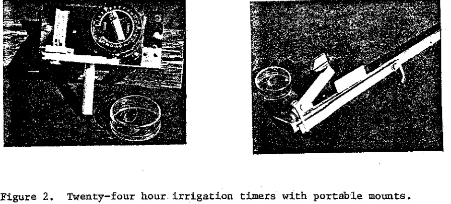
-4-A commercial, 24-hour timer- satisfying the above criteria has been used successfully (Figure 2). It has a main spring windup and direct-reading
Figure 2. Twenty-four hour. irrigation timers with portable mounts.
time indicator integral on the same shaft, and it also has a built-in latch or trip release and an optional start-stop feature.
Trip wires leading from one structure to another have sometimes been used to reduce the number of timers. The wires are rigged so that the opening or closing action of one structure will trigger a simultaneous action in
another structure (see Figure 9). This arrangement has not been satis-factory unless the structures are very close to one another. The trip wires are a nuisance and are often accidently tripped by dogs, birds,
ro-dents, cattle, farm machinery or the farm operator. Preferably, one
timer should be provided for each opening or closing operation, even though this requires twice as many timers and, in some cases, two timers on one
structure. Timers can be mounted for easy movement from one location to another (Figure 2). Then, since only enough units are needed for 1 or 2 days t irrigation sets, their total cost is not large.
Electrical Timers
High-voltage electric clocks normally are not used on individual structures or valves for safety reasons, and electrical power is seldom available in the field. However, programmable electric timer-controllers designed for sprinkler and turf irrigation are easily adapted to agricultural fields and can be used in surface systems. These are especially convenient where water is available on demand, where short, frequent irrigations are desired,
and where solid-set gated pipe systems are used.
With recent advances in technology, battery-powered electronic timers may become practical for automatic irrigation. These require little energy and
can be produced in quantity at a cost competitive with mechanical timers. They are suitable for use where a low energy output can be used to trigger some action in the system. They have no moving parts, can be sealed for protection from dust and water, and potentially have a long trouble-free service life. An electronic timer programmed for automatic flow cutback ir-rigation is being developed and tested at the Snake River Conservation Re-search Center.
4
A new electrical elapsed time meter-/ may also be used for some applications. The operation of this unit is based on a mercury microcoulombmeter in which mercury in a small glass capillary tube is transferred electrochemically
from the anode end of the tube across a gap to the cathode end at a rate proportional to the current. Timing is determined by the time required
for the mercury to transfer and can be varied by changing the current.
This unit can be obtained complete with an optical switch and a potentiometer for making time settings. Its disadvantages are its low load current capa-bility, which complicates interfacing with other components, and its
suscep-tibility to mechanical damage. Water/Soil Moisture Sensors
Irrigation may be started or stopped by instruments or sensors that activate controls electrically when soil moisture reaches predetermined levels. The two commonly used sensors are the tensiometer and soil moisture resistance block. Tensiometers are used to indicate soil moisture tension in the low
range from field capacity (approximately 200 mb) to about 700 mb. They are well suited for use with crops sensitive to soil moisture stress and in sandy soils. They can be obtained with a magnetic switch for use with auto-matic controls. Soil moisture resistance blocks are not as widely used, but
are suited for use in soils law in salts and with crops that can withstand moisture stresses beyond the tensiometer range. Moisture blocks vary and usually must be individually calibrated, or their sensing point set, and re-quire an electronic readout.
Floats or electrode-type water contact sensors and radio transmitter/ receiver units provide another means of time control. With these sensors, the duration of irrigation is determined by the time it takes water to
reach the water sensor/transmitter unit near the lower end of the field.
When water reaches this point, the transmitter is activated and sends a
coded signal to the receiver at the upper end of the field to turn off or
redirect the water. This system works well with borders where it is not
desirable or necessary for runoff to occur. The transmitter/sensor unit
used to stop water diversion into the border is placed at the point where
up-field surface water storage will complete the irrigation. With furrow irrigation, it is necessary to have some runoff for adequate irrigation of the lower end of the field. Thus, the method of operation, location, and
4/
-6--setting of the sensor/transmitter unit would be different. Figure 3 shows radio transmitter/receiver units, developed at Montana State University (2),
Figure 3. Radio transmitter/receiver units used to control irrigation valves for border irrigation.
being tested at the Snake River Research Center. These units were used to control the discharge from low pressure pipeline valves for border irriga-tion. Recent advances in electronic technology, should make radio
trans-mitter/receiver systems more feasible. They may also be used to monitor runoff from the lower end of an irrigated field to reduce runoff and sedi-ment discharge. Radio signals can activate controls at the upper end of the field to make appropriate flow adjustments automatically.
AUTOMATIC CONTROLS FOR OPEN CHANNEL SYSTEMS
Discharge and water levels must be controlled where irrigation water is automatically distributed to a field surface from open channels. Border
and surface flooding systems are easiest to automate because, with uniform field topography, the water is distributed over the entire soil surface be-tween dikes from a single outlet. Furrow systems require additional controls to regulate the flow of water to individual furrows.
Discharge Controls for Furrow Irrigation Systems
Gated surface pipe is recommended for automatic furrow irrigation systems; however, some open channel systems distribute water to individual furrows
from an open ditch. One automatic flow cutback system (4) uses metal or plastic furrow tubes in the side of a lined ditch to supply water to the furrows. The ditch is divided into sections or bays, with all of the tubes in each bay at the same elevation. The tubes in each consecutive downstream bay are at successively lower elevations. Water flows onto the field from
two bays, simultaneously, with a high initial flow from the downstream (lower elevation) outlets, and a reduced or cutback stream from the upstream
Similarly, tubes, orifices, small rectangular chutes, and notched weir outlets in the sides of either lined or unlined distribution ditches have been used. Discharge relationships for these outlets have been developed by other investigators (1, 6, 8, 9). A disadvantage of these type of out-lets for flow control is the labor required to install and maintain the sys-tem. Accurate elevation settings are necessary for good control. Also, the design is rigid, and it is sometimes difficult to adapt the system to dif-ferent crop row spacings and to vary the flow in individual furrows.
Ditch Gates and Checks
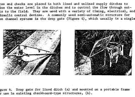
Gates and checks are placed in both lined and unlined supply ditches to raise the water level in the ditches and to control the flaw through out-lets to the field. They are used with a variety of timing, electrical, and hydraulic control devices. A commonly used semi-automatic structure for
open channel systems is the drop gate (Figure 4), which usually is a single
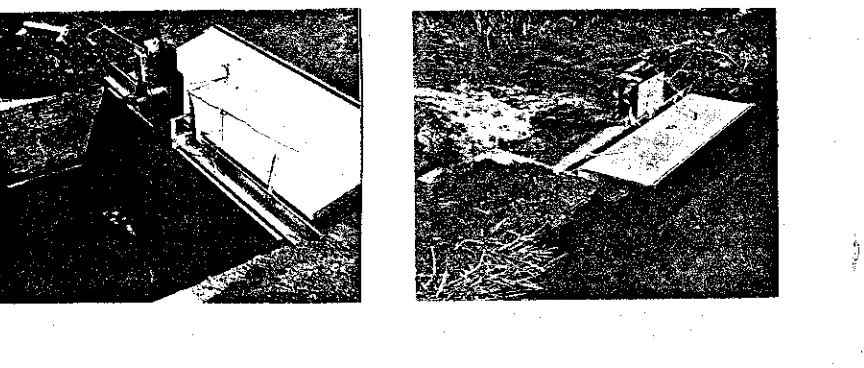
Figure 4. Drop gate for lined ditch (a) and mounted on a portable frame for use in existing checkboard-type structures, (b).
leaf gate hinged at the top and, when open, extends over the ditch. When released, it falls by its own weight to stop the flow of water in the ditch or through the opening where it is placed. It can be permanently mounted on various types of cutoff walls or on a portable frame for moving from one location to another.
The drop-open gate is commonly used as a companion structure to the drop gate. Four designs of this type gate have been developed: (7) (a) apron . gate, (b) drawstring check, (c) center-of-pressure gate, and (d) the tube
outlet gate." The metal apron gate (Figure 5) is hinged at the bottom, and when its top edge is released by a timer, it opens to allow water to flow downstream. The gate lays flat in the bottom of the ditch when open or not in use. A series of these check gates can be used in a ditch to release water sequentially downstream.
-8-Figure 5. Apron gates for unlined ditches with timers having a float-operated start/stop.
Figure 5. portable, timer-controlled irrigation check for lined ditches (a, b) and drawstring check for unlined ditches (c).
section (Figure 6). When closed, the top edge of the flexible dam is sup-ported by a 3.2-mm (1/8") plastic-covered steel cable threaded through grom-mets. The cable is released at the end of the desired irrigation period by a timer or other means to allow the top edge to drop, permitting the water
to flow downstream. This check, when designed for a lined ditch, is port-able and can be easily moved from one location to another. It is well suited for use in the automatic furrow cutback system described above. Its use in this system has reduced labor requirements from 1.2 man hours per ha per irrigation to 0.08 compared to siphon tube irrigation. A modified design can be used in an unlined ditch (Figure Sc).
Figure 7. Center-of-pressure check gate for lined ditches (a) and for un-lined ditches (b, c). The gate in (c) is counterbalanced with a constant-force return spring.
hydrostatic pressure distribution and the resultant center-of--pressure force to open the gate. It is well suited for use as a companion structure to the drop gate. About 3- to 4-cm rise in the water surface is needed to trip the pressure gate after the drop gate closes. When the gate is coun-terbalanced by a constant-farce spring or a weight, it automatically closes after water recedes from the ditch.
A tube outlet gate (Figure 8) is useful in automating pipe turnouts in
Figure 8. Tube outlet gate and drop gate on a concrete pipe turnout struc-ture.
-10-closure. A tube hanger and trip device are also mounted on the clamping band.
Combination turnout gates are needed in most border irrigation systems where more than one turnout exists between ditch check gates. They are
used where it is necessary to first divert water through an opening into a field border, and then terminate irrigation by closing the opening. One combination consists of a drop gate and an apron or other drop-open gate on the same structure (Figure 9). Two timers are used--one to open and one
Figure 9. Combination border turnout gate comprised of a drop gate on the upstream side and an apron gate on the downstream side.
t o close the opening. The timers are set with a slight time overlap so that the next gate opens before the preceding one closes. Conventional, concrete pipe turnouts can be fitted with a drop gate and a tube outlet gate to form a relatively inexpensive combination gate, using existing structures (Fi-gure 8).
These open channel structures can be used in either lined or unlined dit-ches. Many-of them can be built in a farm shop to minimize cost. Data from semi-automatic surface systems indicate that irrigation labor can be reduced as much as 90% compared to conventional systems. In addition, water can be more effectively used, since its application can depend upon
the length of time necessary to replenish the soil moisture rather than upon the farmer's work schedule. Normal work schedules in Idaho usually result in either 12- or 24-hour sets regardless of soil moisture replenish-ment needs.
AUTOMATIC CONTROLS FOR PIPELINE SYSTEMS
able, semi-portable, and solid set surface systems are possible. Automated pipeline systems with good water control can provide greater flexibility in management so that short, frequent irrigations, cutback flow and other water-conserving practices can be used. Most installations use the double pipe system with one pipe (either buried or on the surface) used for conveyance and the second pipe (gated) used for water distribution to the furrows. Automatic controls are being developed for pipe outlet gates, so that gated pipe can serve both conveyance and distribution functions.
Lo-Pressure Automatic Valves
Snake River lo-pressure automatic pipeline valves, developed at the Snake River Conservation Research Center, are designed so that the water pressure within the pipe is used to close the valves. Other investigators use pneu-matically operated valves (3, 5). The working part of the Snake River valve
is a water-inflated bladder or diaphragm within the valve housing (Figure 10).
Figure 10. Snake River irrigation valve showing two types of water-inflatable bladders used inside the valve body.
The bladder is a modified small tire inner tube with a rubber membrane cover-ing vulcanized to each side. The bladder is positioned inside the valve body between two parallel surfaces with a seat or seal ring on each surface
Mole Pipe Coupling
-12-Preasure Top FOr SPodder
Inf!otion
Mop* For Blodetor infiolion otkon
Femme Pip* COuoliro3
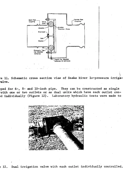
Figure 11. Schematic cross section view of Snake River lo-pressure irriga-tion valve.
developed for 6-, 8- and 10-inch pipe. They can be constructed as single units with one or two outlets or as dual units which have each outlet con-trolled individually (Figure 12). Laboratory hydraulic tests were made to
V alve Controls
A 3-way brass stopcock selector valve controls filling and emptying of the irrigation valve diaphragm. This small valve is operated by a 3-volt DC motor, powered by 2 D-cell batteries. Stainless steel ladder chain on
Delrin sprockets is used to drive the pilot valve through a 90 0 rotation
from one position to the next. The motor rotation is reversed by changing the battery voltage polarity with a DPDT switch. In some cases, the DPDT
switch can also be used as a limit switch. The irrigation valve, with its
associated control unit, can operate independently, requires no energy from
an outside source for operation, and is easily controlled. The motor/ selector-valve unit can be controlled by a mechanical timer, an electronic timer, a programmed timer/controller, or by a radio transmitter/receiver unit.
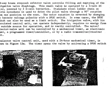
A selector valve control unit, used with a 24-hour mechanical timer, is
shown in Figure 13a. The timer opens the valve by activating a DPDT switch
Figure 13. Selector valve control unit with a 24-hour timer to open an irri-gation valve and a water-filled container to close the valve (a) and a con-trol unit with two timers--one to open and one to close the irrigation valve (b ) .
when it trips. The valve is closed when water from the next irrigation set
is used to fill the water container shown. This activates the DPDT switch to reverse the drive motor. This arrangement can be used when the end of the gated pipe of the next set is adjacent to the valve of the preceding
set, so that water to close the valve can be taken a short distance to the container. This eliminates one timer and assures that the next valve is open
before the preceding one closes. Instead of using the water container, two
timers can be used--one to open and one to close the valve (Figure 13b).
E lectronic timers are also used at the Snake River Conservation Research Center to control the irrigation valves. One timer is designed for use with tensiometers and controls two valves in a predetermined sequence for
auto-matic flow cutback irrigation. This system was used to irrigate a field of
-14-second set, the first valve opened again and the entire stream of water was distributed between both sets to give a reduced or cutback stream size. Irrigation was stopped when the soil moisture tension, as determined by a tensiometer, reached a predetermined value.
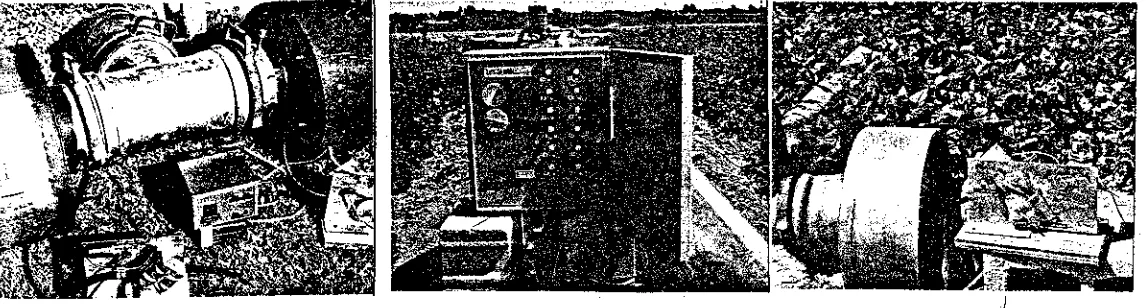
Another electronic timer was designed to activate stepping relays on two or more control units (Figure 14a). With this system, a number of valves can
Figure 14. Irrigation valves with an electronic timer and the associated selector valve control units (a), a commercial programmable irrigation con-troller (b), and a selector valve control unit used with the commercial controller (c).
be controlled with one timer. Each time an electrical pulse is produced by the timer, each relay advances one position. The relay positions are staggered to operate the valves in the desired sequence. A disadvantage of this system is that wires are needed in the field between the timer and each valve.
The selector valve control unit is easy to use with programmed controllers designed for sprinkler and turf irrigation (Figure 14b). Programmed con-trollers commonly use 24-volt AC power for their control functions. Auto-matic irrigation valves tested in this type of system, during 1973, used a 24-volt relay with a DPDT limit switch on the selector valve control unit
(Figure 14c). The valves and their associated controls were used in a
multiset irrigation system to irrigate beans with short frequent irrigations. SUMMARY AND CONCLUSIONS
and automatic systems. In open channel systems, both drop gates and
drop-open gates have been designed to control water discharge into borders and furrows. Gated pipe is recommended for distributing water to the field in an automatic furrow irrigation system. Automatic valves developed for gated
pipeline systems are controlled by battery-powered control units and use
water from the pipeline for operation.
Automatic on-farm controls for surface irrigation are not used extensively. Some are in the experimental stage while others are awaiting further commer-cial development and manufacture. Most field installations have been made in response to pressing water-related or labor probleus. For example,
irri-gation of over 35,000 acres of sugar cane in Hawaii have been semi-automated
as a result of a critical labor and water shortage. This has resulted in a saving of water and has reduced labor requirements about 2/3. Currently, a ' number of factors are expected to increase the use of on-farm automatic
ir-rigation controls. Among these are:
1. The scarcity and high cost of farm labor.
2. An increasing awareness of the need to conserve soil and water
re-sources and decrease irrigation-related pollution.
3. Enactment of legislation to force efficient and prudent use and conser-vation of the farm's soil and water resources.
4. Use of agricultural land for waste disposal. This will require greater use of automatic controls which can also be used fOr general irrigation. 5. Improved irrigation management practices and technology, which will re-quire better an-farm water control and improved irrigation facilities.
6. Improved farm economic conditions, which can result in larger capital
investments in irrigation facilities.
7. Advancements in electronic, materials, and manufacturing technology, which
will make some controls more feasible for irrigation.
8. The energy shortage, which will make automatic surface irrigation systems
more attractive because of their lower energy requirement when compared to sprinkler irrigation.
9. The increased use of gated pipe for furrow irrigation, which is easier to automate than discharge openings from open channels.
REFERENCES
1. Barefoot, A. D. and James E. Garton. The hydraulic properties of sheet metal orifices and circular weirs when used as furrow metering
de-vices on concrete irrigation ditches. Paper presented to the South-west Section Meeting of Am. Soc. Agr. Engr., Baton Rouge, Louisiana, April 1968.
2. Bowman, C. C. Semi-automation of irrigation. Intern. Comm. on Irrig. and Drain., Trans. 7th Congr., Mexico City, Q. 24, Rept. 19, p.
24.271--_ April 1969.
3. Fischbach', Paul E. and Richard Goodding II. An automated surface
irri-gation valve. Agr. Eng. 52(11):584-85, 1971. •
4. Garton, James E. Designing an automatic cut-back furrow irrigation sys-tem. Oklahoma Agri. Expt. Sta. Bull. B-651, 20 pp., 1966.
5. Haise, H. R., E. G. Kruse, and N. A. Dimick. Pneumatic valves for automation of irrigation systems. USDA, ARS 41-104, 21 pp., 1965. 6. Hart, William E. and John Borrelli. Mechanized surface irrigation
-16-7. Humpherys, Allan S. Mechanical structures for farm irrigation. J. Irrig. and Drain. Div., Am. Soc. Civ. Engr., 95(IR 4):463-479, 1969. 8. Sweeten, John M. and James E. Garton. The hydraulics of an automated
furrow irrigation system with rectangular side weir outlets. Trans. Am. Soc. Agr. Engr., 13(6):746-751, 1970.