Volume 2, Issue 12, December 2013
Page 109
Abstract
Main objectives of this paper is to reduce the self phase modulation reduction for WDM transmission using EDFA. For systems operating at 10 Gb/s and above, for lower-bit-rate systems that use high-transmitted powers, the SPM can significantly increase the pulse-broadening effects of chromatic dispersion. In the present work, an alternate approach (reduction of the SPM effect by optimizing core fiber area) is suggested which, is discussed. In fact, there are different methods to reduce this effect.
Keywords: SPM, SBS, SRS,EDFA, Dispersion compensation, self-phase modulation
I.
INTRODUCTION
In this paper we will discuss reduction of SPM for WDM transmission using EDFA. The response of any dielectric to light becomes nonlinear for intense electromagnetic fields and it is also applicable to optical fiber. Although, silica is not a highly nonlinear material , the waveguide geometry that confines light to a small cross section over long fiber lengths make non linear effects very important in design of modern light wave system. The non-linear optical phenomena are stimulated light scattering (SBS and SRS), SPM, XPM and FWM.
Stimulated light Scattering (SBS and SRS)
Rayleigh scattering is an example of elastic scattering for which the frequency (or the photon energy) of scattered light remains unchanged. By contrast, the frequency of scattered light is shifted downward during inelastic scattering. Two examples of inelastic scattering are Raman scattering and Brilliuon scattering. The main difference is that optical phonons participate in Raman scattering, whereas acoustic phonons participate in Brilliuon scattering. Both scattering processes result in a loss of power at the incident frequency. However, their scattering cross sections are sufficiently small that loss is negligible at low power levels. But at high power levels, the nonlinear phenomena of SRS and SBS become important.
Self-Phase Modulation
SPM arises because the refractive index of the fiber has an intensity-dependent component. This nonlinear refractive index causes an induced phase shift, which is proportional to the intensity of the pulse. Thus different parts of the pulse undergo a different phase shift, which gives rise to chirping of the pulses. The pulse chirping in turn enhances the pulse-broadening effects of chromatic dispersion [24]. This chirping effect is proportional to the transmitted signal power so the SPM effects are more pronounced in systems using high-transmitted powers. The SPM-induced chirp affects the pulse-broadening effects of chromatic dispersion and thus is important to consider for high-bit-rate systems that already have significant chromatic dispersion limitations.
Cross-Phase Modulation
The intensity dependence of the refractive index can also lead to another nonlinear phenomenon known as XPM. It occurs when two or more optical channels are transmitted simultaneously inside an optical fiber using the WDM technique. In such systems, the nonlinear phase shift for a specific channel depends not only on the power of that channel but also on the power of other channels. The reason is that the XPM acts in isolation without dispersive effects and is valid only for CW optical beams. In practice, pulses in different channels travels at different speeds. The XPM-induced phase shift can occur only when two pulses overlap in time.
Four Wave Mixing
The power dependence of the refractive index leads to the third-order nonlinear susceptibility. The nonlinear phenomenon, known asFWM, also originates from third-order nonlinear susceptibility. If three optical fields with carrier frequencies 1,2 and 3 co-propagate inside the fiber simultaneously, (3)generates a fourth field whose frequency 4 is
related to other frequencies by a relation 4=1±2±3. Several frequencies corresponding to different plus and minus sign combinations are possible in principle.
II. OPTICAL AMPLIFIER
EDFA iserbium doped fiber amplifiers (EDFA). An erbium-doped fiber is the active medium of an EDFA. It is fabricated in the same way as regular fiber but its core is heavily doped with erbium ions. Since amplification is actually done by the erbium ions, it is important to have as high a concentration as possible of these ions in silica fiber.
Volume 2, Issue 12, December 2013
Page 110
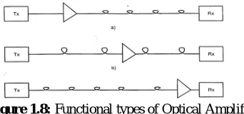
Figure 1.8: Functional types of Optical AmplifiersTo increase the density of erbium ions i.e the number of erbium ions in a volume unit of silica fiber we reduces the core diameter of the erbium doped silica fiber, which reduces its core diameter. The core diameter of and erbium doped fiber ranges from about 3 to about 6 µm; while the core diameter of a regular fiber, ranges form 9 to 11 µm; where the core diameter of a doped fiber is small (meaning it has a small core diameter), the probability of a collision between the erbium ions and the photons of information signal (that is, the signal being amplified) increases. In other words, a small core diameter increases the efficiency of the amplification process. To achieve even more efficient amplification, we not only decrease the core diameter but also concentrate most of the erbium ions in the center region of the small core. The concentration of erbium ions in the center area varies form 100 to 2000 parts per million. An active fiber with concentration of erbium ions as high as 5000 ppm is also available.
Basic Operation of EDFA:
Spontaneous emission is random in phase and occurs without external stimulation (erbium ion moves from lower state to higher state. This state is unstable and thus they return to lower state resulting in release of energy. This is spontaneous emission. When the erbium ions are made to move to lower state (external stimulation) its emission is coherent, called stimulated emission. For stimulated emission to take place emission must be greater then absorption. For that, no. of erbium ions must be greater then at intermediate level then at lower level. This is called condition of population inversion. To attain population inversion we need to pump erbium ions at intermediate level.
III.
Methods to reduce SPM
1.Recovery of pulse by proper filtering. 2.Reduction in effective length. 3.Increase of core area of the fiber
Recovery of pulse by proper filtering:
Since, the main effect of the SPM effect is the broadening of pulse at high power level, so one way to reduce this effect is to slice the output broadened spectrum by proper choice of filters. This method was suggested by Olsson [19] as explained also in literature survey. In this method dispersion shifted fiber is used as transmission media. The pulses at 10 GHz from a ring laser with variable pulse width (9 - 20) ps at a wavelength of 1541 nanometer is amplified to average power of 16 dBm and transmitted to distance of 5 km using DSF. At the output of DSF, an optical band pass filter is used to slice the SPM broadened spectrum. The centre frequency of the band pass filter is 1541.5 nm and the output pulse characteristics are measured with a 40 GHz photo detector. It is observed that output pulse width is almost constant at 14.5 ps for input pulse width between (9-16) ps. This shows that the output pulse width is comparable to input pulse width and hence SPM effect is reduced.
Limitations:
1. One of the main limitations to this approach is with regard to input power. The input power is constant at 16 dBm. Since, the SPM effect comes into place at higher power level so variation of input power from low to high level must taken to understand clearly the SPM effect.
2. The input pulse width is varied from (9-16) ps and remain constant at 14.5 ps In fact, the input pulse width should remain constant and widening of pulse due to the SPM effect must be reduced.
3. Length of DSF fiber is 5 km [19], which is practically very short.
Volume 2, Issue 12, December 2013
Page 111
),/ ( 2 '
eff j
j n n P A
n
Where j = 1,2, n2 is the nonlinear index co-efficient, P is the optical power and Aeff is the effective core area. So
increasing core effective area can decrease the variation in refractive index. This method is used in present work to reduce the SPM effect. The DCF fiber is used and signal is transmitted up to 100 km and core effective area of this fiber is varied from 20 pm2 to 30 pm2.
This method over comes the limitation of first method in the following manner.
1. The input power is varied from 10 dBm to 17.5 dBm to show clearly the effect of the SPM. 2. Input pulse width is constant (59 ps).
3. Distance of transmitting fiber is increased from 5 km to 100 km.
IV.
Simulation Setup to reduce SPM
A 10 Gb/s NRZ signal is transmitted with standard single mode fiber, dispersion shifted (normal) fiber, dispersion shifted (anomalous) and dispersion compensated fiber. The power at the input of each configuration is varied from 10 dBm to 17.5 dBm. By increasing the power, the SPM grows and depletes the signal and the output power decreases. This deteriorating effect is more pronounced at 17.5 dBm, which causes additional pulse broadening. Figure (3.1) and Figure (3.2) shows the block diagram and the circuit diagram. This mainly consists of following three parts.
1. Transmitter Section: This includes data source, driver, optical source and modulator.
2. Fiber Section: Different types of fiber used in this section are standard single mode, dispersion shifted fiber (normal), dispersion shifted fiber (anomalous) and DCF. The signal is transmitted up to distance of 100 km. 3. Receiver Section: This section consists of pre-amplifier, filters, photo-detector and measuring devices.
V. RESULTS & DISCUSSION
With this setup, the signal with frequency 193.41 THz is transmitted up to distance of 100 km by using SSM, DS normal and anomalous and DCF with core effective area of 30 pm2. The input pulse width is 59 ps. It is found that as power is increased from 10
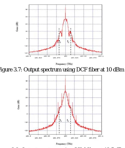
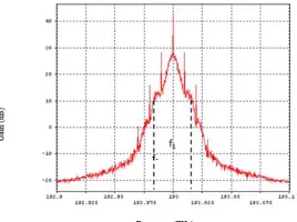
dBm to 17.5 dBm, the pulse gets broadened. Figure (3.3) shows the input spectrum at powers from 10 dBm to17.5 dBm. The figures (3.4) to (3.7) shows the output spectrum by using SSM, DS normal, DS anomalous and DCF at 10 dBm, 12.5 dBm, 15 dBm and 17.5 dBm. There is not much variation in spectrum at this level because at such low power level variation in refractive index is small so there is no pulse broadening. The figures (3.8) to (3.11) shows the output spectrum at 12.5 dBm. The pulse broadening effect is seen in SSM and DS fiber while there no such effect in DCF. The figures (3.12) to (3.15) show the output spectrum at 15 dBm. The pulse broadening effect is large in SSM and DS fiber. The figures (3.16) to (3.19) show the output spectrum at 17.5 dBm. The pulse shape is severely deteriorated in SSM and DS fiber, however, the pulse shape is retained in DCF due to reduction in the SPM effect.
Volume 2, Issue 12, December 2013
Page 112
Figure 3.4: Output spectrum using SSM fiber at 10 dBmFigure 3.5: Output spectrum using DS normal fiber at 10 dBm
Figure 3.6: Output spectrum using DS anomalous fiber at 10 dBm
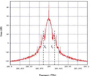
Figure 3.7: Output spectrum using DCF fiber at 10 dBm
Volume 2, Issue 12, December 2013
Page 113
Figure 3.9: Output spectrum using DS Normal fiber at 12.5 dBmFigure 3.10: Output spectrum using DS anomalous fiber at 12.5 dBm
Figure 3.11: Output spectrum using DCF fiber at 12.5 dBm
Figure 3.12: Output spectrum using SSM fiber at 15 dBm
Volume 2, Issue 12, December 2013
Page 114
Figure 3.14: Output spectrum using DS anomalous fiber at 15 dBmFigure 3.15: Output spectrum using DCF fiber at 15 dBm
Figure 3.16: Output spectrum using SSM fiber at 17.5 dBm
Figure 3.17: Output spectrum using DS normal fiber at 17.5 dBm
Volume 2, Issue 12, December 2013
Page 115
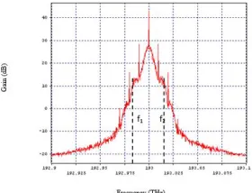
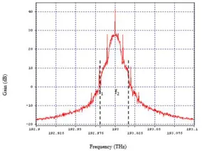
Figure 3.19: Output spectrum using DCF fiber at 17.5 dBmFrom the graphs output pulse width is calculated for different fiber configuration. To calculate the pulse width two frequency are taken where gain is 10 dB (The gain of 10 dB is chosen to show clearly the effect of SPM), with centre frequency 193.48 THz. These frequencies are f1 and f2 and pulse width is calculated by using relation
Pulse width =
1 2
1
f
f
The observations for pulse width are summarized in table 3.1 for SSM, table 3.2 for DS normal, table 3.3 for DS anomalous and table 3.4 DCF.
Table 3.1: SSM fiber
Input power (dBm) Output power (dBm)
f2 – f1
(THz)
Pulse width (ps)
10.013 9.915 .018 50.56
12.513 9.861 .021 47.62
15.013 9.662 .034 29.41
17.513 9.204 .041 24.31
Table 3.2: DS normal fiber
Input power (dBm)
Output power (dBm)
f2 – f1
(THz)
Pulse width (ps)
10.013 10.155 .018 55.56
12.513 10.320 .020 50
15.013 10.205 .034 39.41
17.513 9.108 .040 25
Table 3.3: DS Anomalous fiber
Input power (dBm)
Output power (dBm)
f2 – f1
(THz)
Pulse width (ps)
10.013 10.035 .017 58.82
12.513 10.258 .018 55.56
15.013 10.097 .038 26.32
17.513 8.823 .041 24.39
Table 3.4: DCF fiber
Input power (dBm)
Output power (dBm)
f2 – f1
(THz)
Pulse width (ps)
10.013 9.782 .017 58.82
12.513 9.754 .018 55.56
15.013 9.701 .018 52.63
17.513 9.553 .026 38.46
Volume 2, Issue 12, December 2013
Page 116
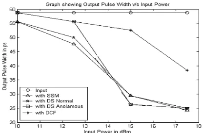
the input spectrum. With SSM fiber as we increase input power from 10 dBm to 17.5 dBm, the width decreases from 59 ps to 25 ps This is expressed in time domain (THz). If we express this in terms in frequency domain then pulse width increases from .018 ps to. 041ps. With DS normal fiber as the power is increased from 10 dBm to 17.5 dBm pulse width increases from .018 THz to .04 THz. With DS anomalous, with increase in power, pulse width increases from .017 THz to .041 THz. Thus, it is observed that the output pulse width is 25 ps at 17.5 dBm, ideally it must be equal to 59 ps which is the input pulse width. The increase in pulse width (in THz.) is reduced by using DCF. By using this fiber, the output pulse width is 39 ps (.026 THz) due to reduction in the SPM effect by increasing core effective area of DCF fiber. In the previous work as presented by Olsson [19], with variation of input pulse width from 9 ps to 16 ps, constant output pulse width of 14.5 ps was shown. However this did not show clearly the effect of SPM. Since instead of variation in input pulse width, variation in output power should be taken which is consider in the present work and effect of SPM is shown clearly. More over the distance of transmitting fiber was only 5 km, which is practically very less. In the present work this distance is increased to 100 km.Figure (3.21) represents variation of output power with input power for SSM, DS normal, DS anomalous and DCF fiber. It is observed that in SSM, DS normal and DS anomalous fiber, there is large deviation in output power, when input power is increased from 15 dBm to 17.5 dBm. However, it is almost constant (9.8 dBm) in DCF.
The reason for constant output power and improvement in pulse width in DCF fiber is due to suppression of the SPM effect by increasing core effective area of the fiber. By increasing core area variation of refractive index with intensity is less, which reduces pulse broadening, and hence the SPM effect is reduced.
Comparison of output power at different core effective area of DCF is done and found that as thecore effective area is increased, the output power increases and become maximum at 30 pm2.
Figure 3.20: Variation of output pulse width with input power.
Figure 3.21: Variation of output power with input power
However, if core area is increased beyond this limit the output power decreases due to introduction of ASE noise effect due to which dispersion increases and pulse broadening occurs again. Table 4.5 shows the variation of output power with core effective area.
Table 3.5: Variation of output power with core effective area. Core area
(pm2)
20 22 24 26 28 30 32
Power (dBm)
9.60 9
Volume 2, Issue 12, December 2013
Page 117
Performance of 10-Gb/s Transmission Systems Using MQW Mach–Zehnder Modulators”, Senior Member, IEEE, Member, OSA[3] C. Rolland, R. S. Moore, F. Shepherd, and G. Hillier, “10 Gbit/s, 1.56 _m multiquantum well InP/InGaAsP Mach– Zehnder optical modulator,” Electron. Lett., vol. 29, pp. 471–472, 1993.
[4] C. Rolland, M. S. O’Sullivan, H. B. Kim, R. S. Moore, and G. Hillier, “10 Gb/s, 120 km normal fiber transmission experiment using a 1.56 _m multiquantum well InP/InGaAsP Mach–Zehnder modulator,” in Proc. Conf. Optical Fiber Commun., San Jose, CA, 1993, paper PD-27.
[5] J. C. Cartledge, C. Rolland, S. Lemerle, and A. Solheim, “Theoretical performance of 10 Gb/s lightwave systems using a III–V semiconductor Mach–Zehnder modulator,” IEEE Photon. Technol. Lett., vol. 6, pp. 282–284, 1994.
[6] D. M. Adams, C. Rolland, N. Puetz, R. S. Moore, F. R. Shepherd, H. B. Kim, and S. Bradshaw, “Mach–Zehnder modulator integrated with a gain-coupled DFB laser for 10 Gbit/s, 100 km NDSF transmission at 1.55 _m,” Electron. Lett., vol. 32, pp. 485–486, 1996.
[7] H. Sano, T. Ido, S. Tanaka, and H. Inoue, “10 Gb/s, 80 km normal fiber transmission by using multiple-quantum well Mach–Zehnder modulator,” in Optoelectron. Commun. Conf., Chiba, Japan, 1996, paper 17D2-4.
[8] P. Delansay, D. Penninckx, S. Artigaud, J.-G. Provost, J.-P. Hébert, E. Boucherez, J. Y. Emery, C. Fortin, and O. Le Gouezigou, “10 Gbit/s transmission over 90-127 km in the wavelength range 1530–1560 nm using an InP-based Mach–Zehnder modulator,” Electron. Lett., vol. 32, pp. 1820–1821, 1996.
[9] J. Yu, C. Rolland, A. Somani, S. Bradshaw, and D. Yevick, “Phase-engineered III–V MQW Mach–Zehnder modulators,” IEEE Photon. Technol. Lett., vol. 8, pp. 1018–1020, 1996.
[10]D. Penninckx, P. Delansay, E. Boucherez, C. Fortin, and O. Le Gouezigou, “InP/GaInAsP _-phase shifted Mach– Zehnder modulator for wavelength independent (1530–1560 nm) propagation performance at 10 Gbit/s over standard dispersive fiber,” Electron. Lett., vol. 33, pp. 697–698, 1997.
[11]D. Penninckx and P. Delansay, “Comparison of the propagation performance over standard dispersive fiber between InP-based _-phase-shifted and symmetrical Mach–Zehnder modulators,” IEEE Photon. Technol. Lett., vol. 9, pp. 1250–1252, 1997.
[12]C. Lawetz, J. C. Cartledge, C. Rolland, and J. Yu, “Modulation characteristics of semiconductor Mach–Zehnder optical modulators,” IEEE J. Lightwave Technol., vol. 15, pp. 697–703, 1997.
[13]P. Delansay, S. Gauchard, H. Helmers, D. Penninckx, S. Gurib, and F. Brillouet, “2.5 Gbit/s transmission over 1086 km of standard single-mode fiber using an integrated laser Mach–Zehnder modulator,” in Proc. Conf. Optical Fiber Commun., San Jose, CA, 1998, paper TuI7.
[14]C. Rolland, “InGaAsP-based Mach–Zehnder modulators for high-speed transmission systems,” in Proc. Conf. Optical Fiber Commun., San Jose, CA, 1998, paper ThH1.