http: // www.gjesrm.com (C) Global Journal of Engineering Science and Research Management
115
NUMERICAL SIMULATION OF COMBUSTION CHARACTERISTICS OF METHANE FLAME
IN AN AXISYMMETRIC COMBUSTOR MODEL
Ibrahim I. A.*1 Gad H. M.2 Shabaan M. M.3
Mechanical Power Engineering Dept., Faculty of Engineering, Port Said University, Port Said, Egypt.
*Correspondence Author: Ibrahim I. A.
Keywords:
Radiation Model, Thermal load, CFD, Air Swirl Number, Non-premixed Flame.Abstract
The present work is a numerical simulation of a non-premixed methane flame performed in a combustor model. CFD studies using ANSYS FLUENT were carried out changing the air swirl number, the inlet thermal load and the combustor exit diameter. The model geometry was created and meshing arrangement was generated using Gambit pre-processing software. To validate the computational procedure, comparison of the present calculations with the experimental data is plotted. Three cases; without radiation model, with the P-1 radiation model and with the discrete transfer radiation model were examined. The results from these three cases were compared with each other and with the experimental data. The discrete transfer and the P-1 radiation models were assessed in a swirling methane non-premixed flame confined in a combustor model. A comparison of realizable k- and standard k- turbulent models is presented. The effects of the inlet thermal load, air swirl number and changing the combustor exit diameter on flame characteristics were studied. The results have shown the significant effect of studied parameters on the flame characteristics and temperature patterns. Increasing the air swirl number and the combustor exit to swirler diameter ratio Dexit/Ds, leads to a decrease in the temperature levels and the flame length. Increasing the inlet thermal load, the high temperature region size, the flame length increased and the distributions of mass fraction for CO2 and O2 demonstrated similar trends with temperature, namely the higher the local temperature the stronger the main products formation.
Introduction
http: // www.gjesrm.com (C) Global Journal of Engineering Science and Research Management
116
the effect of thermal radiation is important even in lights flames, and that the six flux model can be applied in industrial gas furnaces with relative ease, yielding accurate predictions.
Mustafa Ilbas [14] presented a numerical simulation results from the modeling of turbulent non-premixed hydrogen – hydrocarbon flame with and without radiation models. The model results are compared with each other and with experimental data. Ilbas investigated the effect of fuel composition from pure natural gas to hydrogen. The overall flame temperature increase as hydrogen is added or decrease as methane is added to the fuel mixture.
Iker and Ilbas [15] presented temperatures distributions from turbulent chemical reactive flow inside a model combustor for various mixture of hydrogen – methane fuels. They obtained the gas emissions at the combustor exit. The results show that the temperature level increase, CO and CO2 emissions decrease when the hydrogen content is increased in mixture fuel. The standard k-ε model, the realizable k-ε model, the standard k-ω model and the Reynolds Stress model (RSM) in Fluent were used by Jian, B. et al. [16] to predict the turbulent combustion reaction in a methane/air diffusion flame. The results indicated that the simulation of velocities, temperatures and exhaust gas concentrations of combustion products by the standard k-ε model were in good agreement with the experimental results. Related to the experimental conditions, the standard k-ω model gives good prediction. So, it is a reasonable model for the simulation of a methane/air turbulent-jet diffusion flames. Computational fluid dynamics simulations in a swirl combustor were coupled with chemical equilibrium calculations to evaluate the effects of swirl velocity and burner wall temperature on NOx formation. Khanafer, K. and Aithal S.M. [17] developed a fast and robust computational approach to understand the impact of various design parameters on Nox formation in gas-fired swirl burners. The results showed that increasing swirl reduced CO and unburned hydrocarbons. The exit plane NOx did not decrease with increasing swirl. NOx values initially increased with increasing swirl and then decreased.
The present work is amid to validate and simulate a non-premixed methane flame with and without radiation models inside a combustor model. In the present study, the effect of air swirl number, the inlet thermal load and the exit combustor diameter on the combustion characteristics is studied numerically. Validation of the calculation is done by comparing the CFD simulation results with the experimental data. Three air swirl numbers are used it takes the values of 0.4, 0.81 and 1.22. The effects of air swirl numbers in a gas turbine combustor have been investigated.
Turbulence model
In the present work the so-called realizable k- turbulence model provided by ANSYS FLUENT code [18] are used. The realizable k- model is a relatively recent development and differs from the standard k- model in two important ways:
The realizable k- model contains a new formulation for the turbulent viscosity.
A new transport equation for the dissipation rate, has been derived from an exact equation for the transport of the
mean-square vorticity fluctuation.
The term “realizable” means that the model satisfies certain mathematical constraints on the Reynolds stresses, consistent with the physics of turbulent flows. An immediate benefit of the realizable k- model is that it more accurately predicts the spreading rate of both planar and round jets. It is also likely to provide superior performance for flows involving rotation, boundary layers under strong adverse pressure gradients, separation, and recirculation.
Radiation models
ANSYS FLUENT provides four radiation models, which are discrete transfer radiation model (DTRM), P-1 radiation model, Rosseland radiation model, and discrete ordinates (DO) radiation model.
Computational details
Furnace configuration
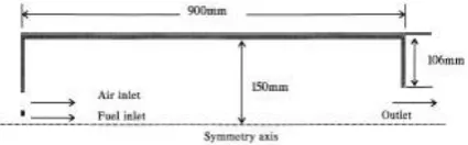
The domain of the model was based on the dimensions of the combustor and burners. The case studied is a cylindrical enclosure of 0.15 m radius and 0.9 m length. Two reactant streams emerge from two separate coaxial jets producing a swirling diffusion flame. The fuel is injected from the central jet whereas the combustion air enters from the outer annular jet. The geometry of this furnace is illustrated in Fig. 1.
Grid System
http: // www.gjesrm.com (C) Global Journal of Engineering Science and Research Management
117
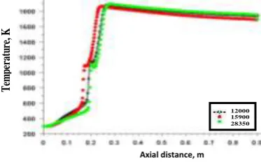
has been created using the GAMBIT pre-processor to discretize the computational domain [19]; the cell type used is the Quad-Map cell, the grid lines were non-uniformly spaced on both radial and axial direction as shown in Fig. 2. Grid independence tests for three different mesh sizes were carried out. The mesh sizes 28350, 15900 and 12000 cells. The influence of the mesh refinement on the distribution of the temperature along the axis of the combustor is shown in Fig. 3. The results indicate that increasing the grid size from 12000 to 28350 has lead to around 1 % difference in the temperature. Considering the computational expense and time, the grid with for the entire domain are used for making the grid analysis. The grid with 15900 cells is considered for further analysis since the flow parameters are found to be independent of mesh size. Thus, the mesh of 15900 was considered suitable for the present calculations. To achieve adequate convergence, the maximum residuals of all variables were plotted after iteration. The residual was normalized by the local variable value and control volume size. The results presented here are considered to be converged with the final peak residuals levels approaching 10-3.
Validation
To validate the computational procedure, comparison of the present calculations with the experimental data reported by Keramida et al [13] was performed. The experimental data were obtained for the combustion process inside furnace of radius of r = 0.15 m and 0.9 m length. Methane gas at a velocity of 15 m/s was burned with air at an axial velocity of 12.28 m /s with swirl number of 0.4. A numerical experiment is carried out, using two different radiation models to analyze the radiative heat transfer in an industrial natural-gas furnace configuration. Comparisons between the experimental data reported by [13] and the calculated results obtained with and without radiation for the radial profiles of the temperature are shown in Figs.4-5. Two consecutive axial locations of x = 0.2 and 0.4 m one near the inlets and one near the middle of the combustor, while the variation of temperature along the combustor centerline is shown in Fig.6. It is shown that using radiation in the computational analysis achieved better agreement between the predictions and the experimental data.
Fig. 1 Geometry of the combustion chamber.
http: // www.gjesrm.com (C) Global Journal of Engineering Science and Research Management
118
Fig. 3 Axial temperature at different mesh sizes
The reduction of the mean temperature in the furnace is significant. In the main combustion zone, where higher temperatures are reached, the effects of radiation are more evident and extend all over the combustor diameter at x = 0.2 m and x = 0.4 m. A comparison of realizable k- and standard k- turbulent models with measured axial temperature using P-1 mode is shown in Fig. 7 while comparison of realizable k- model and standard k- model with measured temperature at x = 0.2 m (no radiation model) is shown in Fig. 8. From these figures there is no big advantage over each of radiation and turbulence models, in terms of predictive accuracy, except the model simplicity and low computational requirements of the P-1 model and realizable k- turbulent model. Finally, the two radiation models have performed similarly. This can be explained by the fact that there is a relative uniformity in the combustion gases concentration field encountered in a natural gas-fired combustor. So the P-1 radiation model and realizable k- turbulent model was chosen for the following calculations.
Fig.4. Comparison of calculated and measured temperature at x = 0.2 m with rk-
model.Fig.5. Comparison of calculated and measured temperature at x = 0.4 m with rk-
model. Axial distance, mT
em
pe
ra
tu
re
, K
12000 15900 28350
0 500 1000 1500 2000 2500
0 0.05 0.1 0.15
Radial distance, m
T
em
p
er
at
u
re
, K
No radiation P - 1 Model Discrete Model Experimental
0 500 1000 1500 2000 2500
0 0.05 0.1 0.15
Radial distance, m
T
em
p
er
at
u
re
, K
http: // www.gjesrm.com (C) Global Journal of Engineering Science and Research Management
119
model.
-with Realizable k Fig.6. Comparison of calculated and measured axial temperature
Fig.7 Comparison of rk-
model and Sk-
model with measured axial temperature (P-1 model).Fig.8 Comparison of rk- model and Sk-
model with measured temperature at x = 0.2 m.Results and discussions
Effect of radiation model
There are many radiation models that can produce accurate solutions but they can be computational expensive. The effect of thermal radiation is important even in flames, and that the discrete transfer and the P-1 radiation models and realizable k-ε turbulent model can be applied in industrial gas furnaces with relative ease, yielding accurate predictions, this was demonstrated by [6,20]. No significant differences are observed between the predicted temperatures with the two radiation models (P-1 radiation model and discrete transfer radiation model). Despite the fact that the overall heat released is the same in all the examined cases, radiative heat transfer is responsible for reducing the size of the high temperature regions of the flame and for shifting them towards the combustor inlet, as it is shown by the temperature maps in Fig. 9. The P-1 radiation model available in ANSYS FLUENT was selected for the present simulation as it produces a quick and acceptable solution in case of non-premixed combustion modelling [1, 6].
0 250 500 750 1000 1250
0 0.15 0.3 0.45 0.6 0.75 0.9
T
em
p
er
at
u
re
, K
Axial distance, m
P-1 rk-ε Model Data P-1 k-ω Model
0 500 1000 1500 2000 2500
0 0.15 0.3 0.45 0.6 0.75 0.9
T
em
p
er
at
u
re
, K
Axial distance, m
No radiation P-1 Model
Data Discrete Model
0 500 1000 1500 2000 2500
0 0.05 0.1 0.15
T
em
p
er
at
u
re
, K
Radial distance, m
No radiation rk-ε
Data
G
lobal
J
ournal of
E
ngineering
S
cience and
R
esearch
M
anagement
http: // www.gjesrm.com (C) Global Journal of Engineering Science and Research Management
120
Fig.9 Temperature maps (°K) (a) No radiation, (b) Discrete transfer model and (c) P-1 model
Effect of inlet thermal load (T.L.)
The effect of changing inlet thermal load of 44, 55 and 75 kW on temperature maps and axial temperature distributions, with constant air mass flow rate at constant air swirl number of 0.4 are shown in figures 10-11. It is shown that, by increasing thermal load (i.e. fuel mass flow rate), the fuel momentum increased due to increase in fuel velocity, so that, the high temperatures regions shifted downstream and inward. The axial temperature increased reaches its maximum at the upstream region and then decreased in the downstream region. Increasing the thermal load, the high temperature regions size increased and the flame length increased.
The effect of changing inlet thermal load (T.L.) on the mass fractions of CO2 and O2 maps, the axial mass fraction of CO2 and O2 are shown in figures 12-15, with constant air mass flow rate at constant air swirl number of 0.4. It is shown that, by increasing inlet thermal load (i.e. momentum flux), the prediction distributions of mass fraction for CO2 and O2 show similar trends with temperature, namely the higher the local temperature the stronger the main products formation. This is due to the local temperature directly affects the component rates of production and consumption.
Fig.10 Temperature maps (°K) (a) T.L. = 44 kW, (b) T.L. = 55 kW and (c) T.L. = 75 kW (b)
0 0.05 0.1 0.15
0 0.15 0.3 0.45 0.6 0.75 0.9
Axial distance, m
R ad ial d d is tan c e , m 0 0.05 0.1 0.15
0 0.15 0.3 0.45 0.6 0.75 0.9
Axial distance, m
R ad ial d d is tan c e , m (a) (c) 0 0.05 0.1 0.15
0 0.15 0.3 0.45 0.6 0.75 0.9
Axial distance, m
R ad ial d d is tan c e , m (b) 0 0.05 0.1 0.15
0 0.15 0.3 0.45 0.6 0.75 0.9
Axial distance, m
R ad ial d d is tan c e , m 0 0.05 0.1 0.15
0 0.15 0.3 0.45 0.6 0.75 0.9
Axial distance, m
R ad ial d d is tan c e , m (a) (c) 0 0.05 0.1 0.15
0 0.15 0.3 0.45 0.6 0.75 0.9
Axial distance, m
R ad ial d d is tan c e , m (b) 0 0.05 0.1 0.15
0 0.15 0.3 0.45 0.6 0.75 0.9
Axial distance, m
R ad ial d d is tan c e , m 0 0.05 0.1 0.15
0 0.15 0.3 0.45 0.6 0.75 0.9
Axial distance, m
R ad ial d d is tan c e , m (a) (c) 0 0.05 0.1 0.15
0 0.15 0.3 0.45 0.6 0.75 0.9
Axial distance, m
R ad ial d d is tan c e , m (b) 0 0.05 0.1 0.15
0 0.15 0.3 0.45 0.6 0.75 0.9
Axial distance, m
R ad ial d d is tan c e , m 0 0.05 0.1 0.15
0 0.15 0.3 0.45 0.6 0.75 0.9
Axial distance, m
R ad ial d d is tan c e , m (a) (c) 0 0.05 0.1 0.15
0 0.15 0.3 0.45 0.6 0.75 0.9
Axial distance, m
http: // www.gjesrm.com (C) Global Journal of Engineering Science and Research Management
121
Fig.11 Centerline axial temperature at different inlet thermal load.
Fig.12 Carbon dioxide mass fraction maps (a) T.L. = 44 kW, (b) T.L. = 55 kW and (c) T.L. = 75 kW
Fig.13 Centerline axial CO2 mass fraction at different inlet thermal load.
Fig.14 Oxygen mass fraction maps (a) T.L. = 44 kW, (b) T.L. = 55 kW and (c) T.L. = 75 kW 280
480 680 880 1080 1280 1480
0 0.15 0.3 0.45 0.6 0.75 0.9
T
em
p
er
at
u
re
, K
Axial distance, cm
T.L. = 44 kW T.L. = 55 kW T.L. = 75 kW
0 0.02 0.04 0.06 0.08 0.1 0.12 0.14 0.16
0 0.15 0.3 0.45 0.6 0.75 0.9
m
as
s f
rac
ti
on
of
c
o2
Axial distance, cm
Fuel mass flow rate = 0.00089 kg/s
Fuel mass flow rate = 0.0011 kg/s
Fuel mass flow rate = 0.0015 kg/s
280 480 680 880 1080 1280 1480
0 0.15 0.3 0.45 0.6 0.75 0.9
T
em
p
er
at
u
re
, K
Axial distance, cm
T.L. = 44 kW T.L. = 55 kW T.L. = 75 kW a
b
c
a
b
http: // www.gjesrm.com (C) Global Journal of Engineering Science and Research Management
122
Fig.15 Centerline axial Oxygen mass fraction at different inlet thermal load.
Effect of air swirl number
To study the effect of air swirl number on temperature patterns, fuel flow rate are maintained without changing. Tests are carried out on three air swirlers which having swirl numbers of 0.4, 0.81, and 1.22. Three runs are carried in order to quantify the air swirl number effect on the temperature patterns which are shown in Fig.16. During these runs, the other operating conditions are remains constants such as air to fuel mass ratio (one air to fuel mass ratio is used) and thermal load of 75 kW. It is observed that, the temperature is increased with the axial distance from the swirler, reached a maximum value and then decreased again with further axial distance. The temperature levels are lower with higher swirl numbers, because the high temperature regions shifts upstream leading to shorter flame length. Being the temperature maps are good description for the temperature distribution inside the combustor in radial and axial directions, therefore, it is chosen and used in the present study. The temperature maps are described by temperature ranges. Each range of temperature is described by a certain color. When the color is more darkened, this indicates that the temperature range is higher. A low temperatures region is found nearest to the swirler at swirl number of 0.4 this low temperatures region is due the high axial air velocity. Increasing the air swirl number, high temperatures region shifted upstream direction nearer to air swirler. It can be explained that, increasing the air swirl number, the recirculation zone became stronger and the mixing rate increased results in small flame size, i.e., shorter flame length but wider flame diameter.
Fig.16 Temperature maps, °K (a) S = 0.4, (b) S = 0.81 and (c) S = 1.22
Effect of combustor end restriction
To study the effect of combustor end restriction on temperature patterns, fuel flow rate are maintained without changing. Tests are carried out on three exit to swirler diameter ratios Dexit/Ds which are 1.6, 1.8, and 12. Three runs are carried in order to quantify the combustor end restriction effect on the temperature patterns which are shown in Figs.17-18. During these runs, the other operating conditions are remains constants such as air to fuel mass ratio (one air to fuel mass ratio is used), air swirl number of 0.4 and thermal load of 44 kW. The combustor should have a restricted end to make the reverse flow zone performs and ends inside the combustor [21]. Increasing the exit to swirler diameter ratios Dexit/Ds, high temperatures region decreased. It can be explained that, increasing the exit to swirler diameter ratios Dexit/Ds, leads to decrease in the flame length and the temperature level.
0 0.02 0.04 0.06 0.08 0.1 0.12
0 0.15 0.3 0.45 0.6 0.75 0.9
m
as
s f
rac
ti
on
of
o2
Axial distance, cm
T.L. = 44 kW T.L. = 55 kW T.L. = 75 kW
b a
http: // www.gjesrm.com (C) Global Journal of Engineering Science and Research Management
123
Fig.17 Effect of combustor end restriction on temperature maps.
Fig.18 Centerline axial temperature at different combustor end restriction.
Conclusions
This paper has presented original research conducted to examine numerically a non-premixed, methane gas flame with no radiation, with the discrete heat transfer and the P-1 radiation models. From the results the following conclusions are presented:
The effect of radiation is significant on flame temperature calculations.
Using of radiative heat transfer in the combustion analysis has produced a better agreement between numerical predictions
and experimental data.
The maximum predicted temperature levels without radiation were higher than those predicted with any the two radiation
models.
The existing of radiative heat transfer reduced the size of the flame region, where maximum temperatures are located.
The overall flame temperature decreases with decreasing the thermal load (i.e. fuel mass flow rate).
The higher the local temperature the stronger the main products formation. This is due to the local temperature directly
affects the component rates of production and consumption.
Increasing the air swirl number, the recirculation zone became stronger and the mixing rate increased results in small flame
size, i.e., shorter flame length but wider flame diameter.
Increasing the combustor exit to swirler diameter ratios Dexit/Ds leads to decreasing in the flame length and the temperature
level.
References
1. Ilbas, M., Yılmaza, I. and Kaplanb, Y., "Investigations of Hydrogen and Hydrogen-Hydrocarbon Composite Fuel Combustion and NOx Emission Characteristics in A model Combustor", International Journal of Hydrogen Energy, Vol. 30, pp. 1139 -1147, (2005).
2. Kontogeorgos, D. A., Keramida, E. P. and Founti, M. A., "Assessment of Simplified Thermal Radiation Models for Engineering Calculations in Natural gas-Fired Furnace", International Journal of Heat and Mass Transfer Vol. 50, pp. 5260–5268,(2007)
3. Chan S.H., Pan X. C. and Abou-Ellail M. M. M., "Flamelet Structure of Radiating CH4-Air Flames", Combustion and
Flame, Vol.102, pp. 438- 446, (1995).
Dexit/Ds =2 Dexit/Ds =1.6
Dexit/Ds =1.8
0 200 400 600 800 1000 1200 1400 1600
0 0.2 0.4 0.6 0.8 1
T
em
p
er
at
u
re
, K
Center line axial distance, m
http: // www.gjesrm.com (C) Global Journal of Engineering Science and Research Management
124
4. Carvalho M.G. and Farias T. L., "Modelling of Heat Transfer in Radiating and Combusting Systems", Trans IChemE, Vol. 76, pp. 175- 184, (1998).
5. Guo H., Ju Y., Maura K., and Niioka T.,"Radiation Extinction Limit of Counter Flow Premixed Lean Methane – Air Flames", Combustion and Flame, Vol. 109, pp. 639–646, (1997).
6. Ilbas, M., "The effect of Thermal Radiation and Radiation Models on Hydrogen–Hydrocarbon Combustion Modeling ",
International Journal of Hydrogen Energy, Vol. 30, pp. 1113 – 1126, (2005).
7. Lefebvre, A.H., "Gas Turbine Combustion". Hemisphere Publishing Corporation, first edition, (1983). 8. Mellor, M., "Design of Modern Gas Turbine Combustors", Academic Press, (1990).
9. Syred, N., Beer, J.M, "Combustion in Swirling Flows: A review", Combustion and Flame, Vol. 23, pp. 143–201, (1974). 10. Ilbas, M., "CFD Prediction of Coupled Radiation Heat Transfer and Soot Production in Turbulent Flames", Twenty-Sixth
Symposium (International) on Combustion/The Combustion Institute, pp. 2379–2386, (1996).
11. Bakic, V., Belosevic, S., "Fuel–Air Ratio Influence on Mixing Processes Between Premixed Acetylene Flame and Surrounding Air", Thermal Sci., Vol.4 pp. 33–40, (2000).
12. Kontogeorgos, D. A., Keramida, E. P. And Founti, M. A., "Assessment of Simplified Thermal Radiation Models for Engineering Calculations in Natural Gas-Fired Furnace", International Journal of Heat and Mass Transfer, Vol. 50, pp. 5260 – 5268, (2007).
13. Keramida, E. P, Liakos, H. H., Founti, M. A., Boudouvis, A. G. And Markatos, N. C.,"Radiative Heat Transfer in Natural Gas – Fired Furnace", International Journal of Heat and Mass Transfer, Vol. 43, pp. 1801 – 1809, (2000).
14. Mustafa Ilbas, “The effect of thermal radition and radition models on hydrogen – hydrocarbon combustion modelling", Int. J. of Hydrogen Energy, Vol. 30, pp. 1113-1126, (2005).
15. Yılmaz, I. And İlbaş, M., “Experimental and Numerical Investigations of Methane Addition on Hydrogen Combustion in a
Developed Combustor”, International of Hydrogen Energy Congress and Exhibition Istanbul-Turkey, (2005).
16. Jiang, B., Li X., Liang, H. and Uang, G., "Study on NO Formation in CH4/Air Jet Combustion", Chinese J. Chem. Eng., Vol.14, pp.723- 728, (2006).
17. Khanafer, K. and Aithal, S.M., “Fluid-dynamic and NOx computation in swirl burners ”, International Journal of Heat
and Mass Transfer, Vol. 54, pp. 5030–5038, (2011).
18. ANSYS FLUNET Program User Guide, (2013).
19. GAMBIT Program User Guide, September (2007).
20. Ibrahim, I. A. and Shabaan, M. M., “Numerical Simulation of Methane Combustion with and without Radiation Models”,
PSERJ, Vol. 17, No. 1, pp. 1 – 7, March, (2013).