[Lami* 4(5): May, 2017] ISSN 2349-4506
Impact Factor: 2.785
G
lobal
J
ournal of
E
ngineering
S
cience and
R
esearch
M
anagement
EVALUATING THE EFFECT OF LATERAL SOIL MOVEMENT RATE ON THE
BEHAVIOR OF PILES IN SAND USING PLAXIS
Ahmed Saad. Al- Lami*, Kais T. Shlash, Mohammed A. Al-Neami
*
Ph. D. Student, University of Technology, Building and Construction Engineering Department,
Baghdad, Iraq
Professor, Civil Engineering Department, Uruk University - Baghdad, Iraq
Assist. Professor, Building and Construction Engineering Department, University of Technology,
Baghdad, Iraq
DOI: 10.5281/zenodo.573752
KEYWORDS
:
Single Pile, pile groups, Lateral Soil Movement, Bending moment.ABSTRACT
Pile foundations are not only used to support heavy structures and can act in the dual role of carrying the applied load to deeper and strong layers, but also to resist lateral loads generated from many sources as well as earthquake, earth pressure, waves, wind and soil movement due to creeping slop or excavation works.
Piles response to external effects is divided into a passive pile and active pile. When the piles are subjected to lateral soil movements, these piles are known as passive piles. On the other hand, active piles referred to a pile subjected to external vertical and/or horizontal force.
Soil movement is encountered in practice when piles are placed in an unstable slope, landslides, adjacent to deep excavation, tunnel operation, marginally stable riverbank with high fluctuating water level and also in piles supporting bridge abutment adjacent to approach embankments.
PLAXIS 3D 2013 geotechnical finite element package which present 3- dimensional analysis for soil was utilized to build a numerical model of single pile and pile groups in lateral soil movement with different soil movement rates. The model confirmed using previous researches. The model verification shows favorable agreement with the measured horizontal pile deflections and bending moments by choosing appropriate parameters.
Results from three-dimensional finite element show that high soil movement rates gave high horizontal displacement and bending moment then the lower rates. Also, the increasing of soil movement rate has more impact on the behavior of the single pile compared with the effect on pile groups under the same rate.
INTRODUCTION
There are many engineering works that may lead to affect the pile to lateral movement of ground like piles in an unstable slope, landslides, adjacent to deep excavation, piles supporting abutment adjacent to approach embankments and also in tunnel operation.
During lateral movement, blocks of mostly intact, surficial soil displace downslope or towards a free face along a shear zone that has formed within the liquefied sediment. The amount of lateral displacement due to lateral movement typically ranges from a few centimeters to several meters and can cause considerable damage to an engineering structure and lifelines (Bartlett and Youd, 1995).
[Lami* 4(5): May, 2017] ISSN 2349-4506
Impact Factor: 2.785
G
lobal
J
ournal of
E
ngineering
S
cience and
R
esearch
M
anagement
PLAXIS PROGRAM DETAILS
The program was developed to carry out a 2D finite element code for the analysis of river embankments in soft soils, but quickly spread to all geotechnical areas. Only in 2001 the 3D finite element calculations were developed, resulting in the 3D Tunnel program (Brinkgreve 2013).
PLAXIS 3D is equipped with features to deal with various aspects of complex geotechnical structures and construction processes. Geotechnical applications require advanced constitutive models for the simulation of the non-linear, time dependent and anisotropic behavior of soils and/or rock. In addition, since soil is a multi-phase material and special procedures are required to deal with hydrostatic and non-hydrostatic pore pressures in the soil. Although the modeling of the soil itself is an important issue, many projects involve the modeling of structures and the interaction between the structures and the soil.
PLAXIS PHILOSOPHY IN DESIGN EMBEDDED PILE
PLAXIS can simulate the embedded pile like a beam and this beam can cross the soil model at any arbitrary orientation and with any arbitrary location (Figure 1a). The pile is linked to the inclosing soils by means of special interfaces which are skin interfaces and foot interfaces.
Although volume is not considered according to the design philosophy of the embedded pile, a particular elastic volume around the pile (elastic zone) whose dimension is equivalent to the pile diameter is assumed, in which the plastic behavior is neglected (Figure 1b).
(a) Embedded pile with arbitrary direction
(b) Elastic region around embedded pile
Figure (1): Schematization of single embedded pile (PLAXIS 3D) [Dao 2011].
Pile-Soil Interaction
When a mesh is generated, new nodes on the pile will be created. The pile-soil interaction was made through the connection between new pile nodes and existing soil nodes due to the special interface modeling. An elasto-plastic model is used to describe the behavior of the interfaces.
The interaction may involve a skin resistance (unit of force per length) and a tip resistance (unit of force) whose sum is considered as the bearing capacity of embedded pile. For both the skin resistance and the tip resistance, a failure criterion is applied to distinguish in between the interface elastic behavior and the interface plastic behavior.
The Embedded Pile Parameters
[Lami* 4(5): May, 2017] ISSN 2349-4506
Impact Factor: 2.785
G
lobal
J
ournal of
E
ngineering
S
cience and
R
esearch
M
anagement
Because of being considered as a beam, the pile is set up in linear elastic properties of a beam element which is presented in parameters of the Young Modulus (E) and the unit weight (γ) of pile material. Subsequently, the geometric properties of the pile are defined in terms of both predefined shapes (Massive circular pile, Massive tube, or Massive square pile) and real pile diameter which determines the elastic zone around the pile.
Alternatively, a “user defined” type may be used to define the pile shape by means of pile’s cross section (A) and Moments of inertia. On the other hand, the properties of the pile-soil interaction are defined by skin resistance and base resistance.
PROBLEM GEOMETRY BOUNDARIES AND MESH GENERATION
Finite element analysis software Plaxis 3D foundation was used for the investigation of passive pile behavior under lateral soil movement. In order to carry out a parametric study, other properties should be kept constant while the effect of the change in a certain property is being investigated.
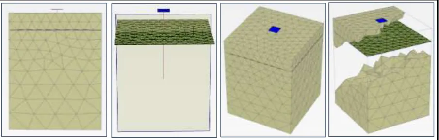
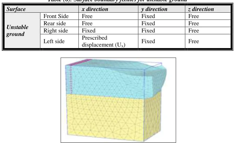
A simple shear box model was used to represent the movement of the upper soil relative to the lower soil (Kourkoulis et al. 2011, 2012). Figure (2) shows the geometric illustration of the shear box model, the Shear box models provide control of the number of variables and it prevents the redundant uncertainties. Unstable ground was modeled by using uniform predefined horizontal displacements. Stability of bottom soil was provided with surface fixities.
Consequently, shearing zone was formed between unstable and stable soils just like in real landslide cases. Embedment of the pile into stable stratum caused the development of passive resistance in the pile.
For standard model with single pile, the mesh comprised of (3685) elements with (6253) nodes while a greater accuracy can be achieved by using a higher number of elements to model the soil and pile, this leads to use fine mesh, the fineness mesh lead to slight increase in the accuracy of results, but required longer time to analysis the model.
The base face of the model mesh was fixed in all direction x, y and z. The surface of the mesh was not fixed in any direction. In stable zone, the faces were fixed in all direction.
Figure (2): geometry of the model from many views.
Soil properties
[Lami* 4(5): May, 2017] ISSN 2349-4506
Impact Factor: 2.785
G
lobal
J
ournal of
E
ngineering
S
cience and
R
esearch
M
anagement
elastic perfectly plastic Mohr-Coulomb model involves five input parameters, i.e. Young's modulus E and Poisson's ratio ⱱ for the soil elasticity; friction angle φ and cohesion c for soil plasticity and ψ as a dilation angle.
Interface elements
Interface elements are different from the sense that they have pairs of nodes instead of single nodes. Just like the plate elements, interface elements are numerically integrated by using 3-point Gauss integration. The position and numbering of the nodes and integration points is indicated in Figure (3). The distance between the two nodes of a node pair is zero. Each node has three translational degrees of freedom (ux , uy , uz ). As a result, interface elements
allow for differential displacements between the node pairs (slipping and gapping) (Goodman et al., 1968 and Van Langen, 1991).
Figure (3): Local numbering and positioning of nodes (•) and integration points (x) of a 16-node interface element
To model the interaction between two materials, the program PLAXIS has an element called "interface". To define the properties of an interface, exist two possibilities. The first is to assign a material to the interface, staying the interface defined with the properties of this material. The second is to use the parameter Rinter. This parameter has
a reduction effect that is used to define the parameters from the interface, using reducing parameters from the material assigned for the surrounding soil.
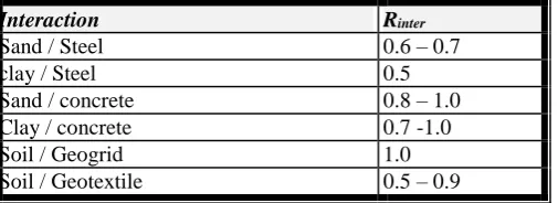
In general, for real soil-structure interaction the interface is weaker and more flexible than the surrounding soil, which means that the value inter of Rinter should be less than 1. Table (1) presents some values proposed in Dennis
Waterman (2006) for the value of Rinter.
Table (1): Values for Rinter proposed in Dennis Waterman (2006).
Pile model
For all movement rates and all other conditions, the model tests presented previously, the measured bending moments on the piles were well below the yield moment. Therefore, the piles used in the model test were represented as an isotropic elastic hollow pile. The internal and the external diameters of the isotropic elastic hollow piles were the same as for the pile used in the model tests.
Rinter
Interaction
0.6 – 0.7 Sand / Steel
0.5 clay / Steel
0.8 – 1.0 Sand / concrete
0.7 -1.0 Clay / concrete
1.0 Soil / Geogrid
[Lami* 4(5): May, 2017] ISSN 2349-4506
Impact Factor: 2.785
G
lobal
J
ournal of
E
ngineering
S
cience and
R
esearch
M
anagement
PROBLEM PHASES
The calculation consists of four phases for simulating each problem in this study. The initial phase which is the first phase defines the soil, which consists of the generation of the initial stresses using the Ko procedure. The
second phase (phase one) presents the installation of piles and pile capes with their working loads using plastic type of calculation where static load is activated. The third phase (phase 2) is to simulate the horizontal movement with a surface displacement.
Verification with other studies.
To ensure PLAXIS 3D 2013 accurate in analysis the pile undergo lateral soil movement, results was compared with a previous research conducted by Al-Abboodi et al., 2015 how selected to compare PLAXIS with the laboratory tests that carried out by Ghee, 2009, and with results from FLAC3D as finite differences programmer in Ghee, 2009 theoretical work.
These studies (experimental and theoretical) didn’t mention to the rate of soil movement, these studies have been chosen in order to validate the proposed procedure in PLAXIS that include soil movement rate.
The shear box used by Ghee 2009 had dimensions of (1000 1000 800 mm) with sliding layer 400 mm. the pile have total length 1200 mm, the embeded length 700 mm and the model had free-head and free-tip aluminium instrumented pipe with outer diameter of 50 mm and wall thickness of 1.0 mm.
Young’s modulus of 70000 106 N/m2 and Poisson’s ratio of 0.3 have been used in the analysis of the pile. A
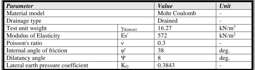
Mohr–Coulomb elastic–plastic constitutive model was assumed for the soil. The properties of the sand used in the tests are illustrated in Table (2).
Figure (4) clarifies the horizontal movement decplacement profiles of the pile. It can be obseved that the Plaxis results with two speeds in both analytical and measured results show behavior like a rigid pile with a rotational point located closed to the pile tip. The deflection profile predicted along the pile length including the magnitude of maximum deflection at soil surface by PLAXIS showed a close matching with the test results.
Table (2): Properties of tested sand (Al-Abboodi et. al., 2015).
Parameter Value Unit
Material model Mohr Coulomb - Drainage type Drained - Test unit weight γd(unsat) 16.27 kN/m3
Modulus of Elasticity Es' 572 kN/m2
Poisson's ratio ν 0.3 - Internal angle of friction φ' 38 deg. Dilatancy angle Ψ 8 deg. Lateral earth pressure coefficient KO 0.3843 -
[Lami* 4(5): May, 2017] ISSN 2349-4506
Impact Factor: 2.785
G
lobal
J
ournal of
E
ngineering
S
cience and
R
esearch
M
anagement
Figure (4): Predicted and measured deflection along pile
Figure (5): Predicted and measured bending moment along the pile
Material Used
The piles were chosen as embedded piles made of aluminum materials, and intersect with pile caps as grouped. The pile caps were presented as plates with properties listed in Table (3).
Table (3): Material properties of boundary walls and cap plates.
Parameter Value Unit
Young´s modulus E 200x106 kN/m2
Unit weight γ 78.5 kN/m3
Thickness d 80 mm
Tables (4) and (4) list the properties of soil and pile respectively which used in this study.
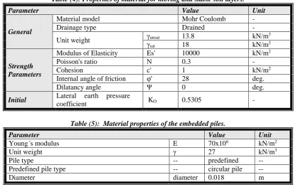
Table (4): Properties of material for moving and stable soil layers.
Parameter Value Unit
General
Material model Mohr Coulomb - Drainage type Drained - Unit weight γunsat 13.8 kN/m
3
γsat 18 kN/m3
Strength Parameters
Modulus of Elasticity Es' 10000 kN/m2
Poisson's ratio Ν 0.3 - Cohesion c' 1 kN/m2
Internal angle of friction φ' 28 deg. Dilatancy angle Ψ 0 deg.
Initial Lateral earth pressure
coefficient KO 0.5305 -
Table (5): Material properties of the embedded piles.
Parameter Value Unit
Young´s modulus E 70x106 kN/m2
Unit weight γ 27 kN/m3
[Lami* 4(5): May, 2017] ISSN 2349-4506
Impact Factor: 2.785
G
lobal
J
ournal of
E
ngineering
S
cience and
R
esearch
M
anagement
Skin friction distribution type linear -- Skin resistance at the top of the embedded pile Ttop, max 10 kN/m
Skin resistance at the bottom of the embedded pile Tbot, max 10 kN/m
Base resistance Fmax 1 kN
PROBLEM MODELING AND BOUNDARIES
To define the surface boundaries and modeled the pile under lateral soil movement problem the surface prescribed displacement property was used to redefined the problem. In modeled this problem the movement in three directions must be defined (x, y and z), this definition must be for front and rear side surface. The vertical movement in (z) direction is allowed for all surfaces but the prevented the movement in (y) direction. The horizontal movement in (x) direction was allowed in front and rear side surface with amount of uniformly distributed prescribed displacement (ux) that are defined on left and right side of box in zone of movement soil,
Table (6).
For analysis of the calculation phases which fully completed, excessive deformations and spilling of soil body at the right hand side were observed especially depending on the assigned material properties and the amount of prescribed displacements (Figure 6).
Table (6): Surface boundary fixities for unstable ground
Surface x direction y direction z direction
Unstable ground
Front Side Free Fixed Free Rear side Free Fixed Free Right side Fixed Fixed Free Left side Prescribed
displacement (Ux)
Fixed Free
Figure (6): Spilling of movement layer of soil from right hand side.
RESULT AND DISCUSSIONS
In order to evaluate the effect of moving rate of ground surface causing a sliding for single pile and pile groups, four tests were conducted in PLAXIS 3D for each case (single pile, 2x1 pile group, 1x2 pile group and 2x2 pile group). In all cases, the lateral soil movement rates were selected as (5, 7.5, 10 and 12.5 mm/min). In all tests the length to diameter ratio (L/D=30) was used, loose sand was used with relative density of 30 % and for pile groups (pile spacing to the diameter ratio) S/D equals 3.
[Lami* 4(5): May, 2017] ISSN 2349-4506
Impact Factor: 2.785
G
lobal
J
ournal of
E
ngineering
S
cience and
R
esearch
M
anagement
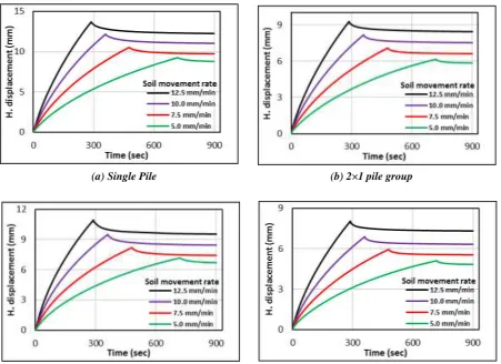
Figure (7) show the variation of horizontal displacement of pile cap of single pile and pile groups with time. It is readily observed that there is an increasing in horizontal displacement of pile cap with time until movement of layer is stopped then a slight decreasing is occurred for single pile and piles groups.
The pile horizontal displacement in all test is less than 25% of single pile and all pile groups configuration and for all movement rates with corresponding amount of soil movement, these observations indicate that the soil in sliding layer flowed around the pile. Same observation is noticed by (Ghee, 2009).
(a) Single Pile (b) 2×1 pile group
(c)1×2 pile group (d) 2×2 pile group
Figure (7): Variation of horizontal displacement of foundation with time for different lateral soil movement rates and different pile configuration.
To invistagate the maximum horizontal displacement and maximum bending moment, PLAXIS 3D 2013 was used with different rates. Foure rates are studied (1, 25, 50 and 100) mm/min. The movement rate of 100 mm/min can be classified as a subrapid velocity and the movement rate of 1 mm/min classified as sub-moderate.
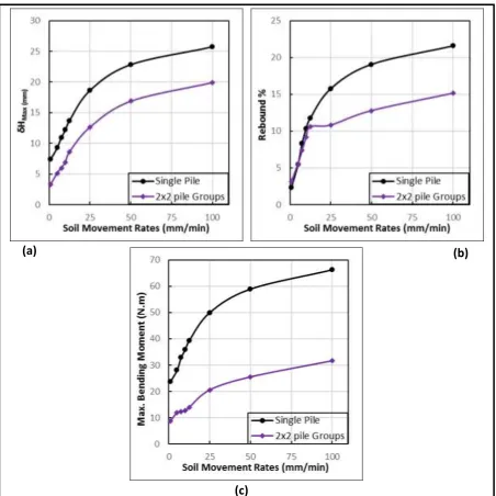
Figure (8-a) shows the relationship between the movement rate and the maximum horizontal displacement in the pile cap at single pile and 2×2 pile group's configuration, the rebound ratio and maximum bending moment along the pile shaft are depicted in Figures (8-a, b and c) respactiviely.
[Lami* 4(5): May, 2017] ISSN 2349-4506
Impact Factor: 2.785
G
lobal
J
ournal of
E
ngineering
S
cience and
R
esearch
M
anagement
From Figure (8-b) it can be conculded that the at low speeds of movement, the rebound ratio for single is approximately the same to that pile group but when the speed is greater than of 25 mm/min, the rebound in pile group is sligtly increases while in case of single pile the increasing in rebound is clearly appeared.
Figure (8) Single pile and pile groups response in different soil movement rates.
CONCLUSIONS
Based on the numerical models results, the following conclusions can be drawn
1) PLAXIS 3D 2013 software has an ability to predict the response of single pile and pile groups under lateral soil movement with a good accuracy.
2) Slow movement rate has a high effect on maximum bending moment and maximum horizontal displacement at pile cap than a high movement rate.
(a)
(b)
[Lami* 4(5): May, 2017] ISSN 2349-4506
Impact Factor: 2.785
G
lobal
J
ournal of
E
ngineering
S
cience and
R
esearch
M
anagement
3) Single pile is highly affected by increasing of soil movement rate compared with pile group under the same rate.
REFERENCES
1. Al-Abboodi I.,Sabbagh T. T., and Al-Jazaairry A., (2015), “Modelling the Response of Single Passive Piles Subjected to Lateral Soil Movement using PLAXIS”, International Journal of Engineering Research & Technology Vol. 4, No. (3), pp. 176-180.
2. Bartlett S. F. and Youd T. L., (1992),“Empirical analysis of horizontal ground displacement generated by liquefaction-induced lateral spreads”, Technical Report No. NCEER-92-0021. National Center for Earthquake Engineering Research. State University of New York. Buffalo.1992: 5-14-15.
3. Brinkgreve R.B.J. (2013),“Validating Numerical Modelling in Geotechnical Engineering”, NAFEMS, UK.
4. Dennis Waterman, (2006), “Structural elements and excavations”, Presentation in CG1 Chile 5. Ghee E. H., (2009),“The behaviour of axially loaded pile subjected to lateral soil movements”, a thesis
presented in fulfilment of the requirement for the degree of doctor of philosophy of Griffith University. 6. Kourkoulis R., Gelagoti F., Anastasopoulos I., and Gazetas G., (2011), “Slope stabilizing piles and
pile-groups: Parametric study and design insights”, Journal of Geotechnical and Geoenvironmental Engineering, Vol. 137, No. 7, pp. 663–678.
7. Kourkoulis R., Gelagoti F., Anastasopoulos I., and Gazetas G., (2012), “Hybrid method for analysis and design of slope stabilizing piles”, Journal of Geotechnical and Geoenvironmental Engineering, Vol. 37, No. 1, pp. 1-14.
![Figure (1): Schematization of single embedded pile (PLAXIS 3D) [Dao 2011].](https://thumb-us.123doks.com/thumbv2/123dok_us/8887868.1823472/2.595.136.466.399.553/figure-schematization-of-single-embedded-pile-plaxis-dao.webp)