Adv. Radio Sci., 7, 83–88, 2009 www.adv-radio-sci.net/7/83/2009/
© Author(s) 2009. This work is distributed under the Creative Commons Attribution 3.0 License.
Advances in
Radio Science
Improving MIMO-OFDM decision-directed channel estimation by
utilizing error-correcting codes
P. Beinschob, M. Lieberei, and U. Z¨olzer
Department of Signal Processing and Communications, Helmut-Schmidt-Universit¨at/University of the Federal Armed Forces Hamburg, Germany
Abstract. In this paper a decision-directed Multiple-Input Multiple-Output (MIMO) channel tracking algorithm is en-hanced to raise the channel estimate accuracy. While DDCE is prone to error propagation the enhancement employs chan-nel decoding in the tracking process. Therefore, a quantized block of symbols is checked on consistency via the channel decoder, possibly corrected and then used. This yields a more robust tracking of the channel in terms of bit error rate and improves the channel estimate under certain conditions.
Equalization is performed to prove the feasibility of the obtained channel estimate. Therefore a combined signal con-sisting of data and pilot symbols is sent. Adaptive filters are applied to exploit correlations in time, frequency and spatial domain. By using good error-correcting coding schemes like Turbo Codes or Low Density Parity Check (LDPC) codes, adequate channel estimates can be acquired even at low sig-nal to noise ratios (SNR). The proposed algorithm among two others is applied for channel estimation and equalization and results are compared.
1 Introduction
MIMO-OFDM combines two powerful techniques for next generation wireless communication systems. For develop-ment accurate channel estimates of certain environdevelop-ments are required to derive realistic parameters for Monte-Carlo sim-ulations of MIMO channels. They can be obtained by ap-plying a MIMO system and an appropriate channel estima-tion algorithm in the respective environment. In Akhtman and Hanzo (2007) a channel tracking algorithm based upon a MIMO Recursive Least Square (RLS) algorithm is proposed. MIMO RLS channel estimation has obvious advantages over
Correspondence to: P. Beinschob ([email protected])
traditional interpolation approaches. On the one hand, time and spatial diversity can be exploited which makes it suitable for spatial multiplexing MIMO system design approaches even in fast time-varying environments. On the other hand, due to the filter structure the output depends only on the cur-rent input, therefore the channel estimate is available almost delay-free rather then after whole frame processing as in in-terpolation if time variance is reflected.
The paper is structured as follows. The system model is described in Sect. 2. The employed MIMO-OFDM RLS al-gorithm is reviewed in Sect. 3. The enhancement to this algo-rithm is shown in Sect. 4. Finally, the performance of Turbo Codes and LDPC Codes as channel coding schemes in this context is compared using the mean square error of the chan-nel estimate and the MIMO system’s bit error rate (BER) versus SNR in Sect. 5, before concluding in Sect. 6.
2 System model
The vector of received values r at the time sample mof a MIMO system is a superposition of L·NT previously send samples and the currentNT samples. It is given by
r[m] = L X
l=0
H[l, m] ·s[m−l] +w[m], (1)
where s[m] denotes the current vector of symbols of ev-ery transmit antenna, w an identically, independently dis-tributed (i.i.d.) additive white Gaussian noise term and H the MIMO channel matrix. The past sent samples are de-noted by s[m−l], forl6=0. For simulations the data symbols of theKsubcarrier are modulated by an inverse Fast Fourier Transform (IFFT). Every value corresponding to a transmit antenna of the resulting vectors is transmitted using the for-mula above. If a time variant channel is assumed, for every samplemthe channel matrix differs from the previous one. It is modeled such that the movement of the terminal results
84 P. Beinschob et al.: Improving MIMO-OFDM decision-directed channel estimation in a Doppler shift of the send signal. This property is
in-tegrated in H[l, m]by first generating independent channel matrices from everym, land second filtering over timemfor every taplwith the Jakes spectrum, that reflects the spread of the Doppler shifts in the frequency domain. In a simulation only a finite number of Doppler frequencies can be realized, therefore the Jakes spectrum is sampled at 16 non-zero fre-quencies. The result is a continuously time-varying channel, even for small terminal velocities (P¨atzold, 1999).
In the frequency domain the system model in Eq. (1) can be described in the time invariant case as
r[n, k] =H[n, k] ·s[n, k] +w[n, k], (2) wheren denotes the time index of an OFDM symbol and k its subcarrier index. The MIMO channel coefficients Hr,t, r=1, . . . , nR, t=1, . . . , nT are normal i.i.d. random variables for every tap. As described above they may vary over time and frequency n, k in a MIMO-OFDM frame. Through the whole discussion and in the simulations a frame consists of 256 OFDM symbols of which the first 128 are pilots to train the adaptive filters. The source bits are coded using modern coding schemes like Turbo Codes and LDPC Codes. The codes are constructed such that one codeword fits in an OFDM symbol. Thus for aM-QAM modulation scheme and code rateRCthe codeword length set to
nC=K·RC·log2M. (3)
It is important for the ability to track time-variant channels that the symbols in a transmitted OFDM symbol can be de-coded at once.
For all simulations presented pilots and data symbols are send to compute a bit error rate as a confidence level for the estimated channel impulse response.
The pilot tones are organized as in code division multi-plexing (CDM) manner. A single symbol is mapped to a se-quence. The sequences are pairwise orthogonal thus prevent-ing mutual interference. Each transmit antenna sends its own sequence. A set of orthogonal sequences are (Frank-Zadoff-Chu, 1972) sequences which are used for channel estimation in the training phase.
3 Adaptive MIMO RLS channel estimation
The employed MIMO-OFDM-Recursive Least Squares (RLS) algorithm, proposed in Akhtman and Hanzo (2007), is due to find a solution to the Wiener-Filter problem: minE{(r[k] −H[k] ·s[k])2}. (4) The global solution is called Wiener-Hopf equation
H[k] =(8−1[k]θ[k])H. (5)
with
8[k] =Ens[k] ·sH[k]o ∀k
θ[k] =Ens[k] ·rH[k]o ∀k. (6) In general the expectation values are unknown and must be estimated. To derive the RLS algorithm Eq. (4) is modified to get the following optimization problem: The channel es-timateH˜[n, k]at time instantnon subcarrierkshould map the data symbols s[n, k]in such a way that the distance to the actually received symbols is minimized
minε=mink˜r[n, k] − ˜H[n, k] ·s[n, k]k2. (7) The RLS implementation of this solution replaces the expec-tation value with an exponentially weighted sum. Therefore the matrices can be calculated recursively:
8[n, k] = n X
m=1
ξn−ms[m, k]sH[m, k]
=ξ8[n−1, k] +s[n, k]sH[n, k] (8) and
θ[n, k] = n X
m=1
ξn−ms[m, k]rH[m, k]
=ξθ[n−1, k] +s[n, k]rH[n, k]. (9) Still Eq. (5) is the global minimum and used to calculate the channel matrix H. By theξ weighting, newer samples have greater impact on the channel estimate thus adaptivity on time variant channels can be achieved. For lower SNR aξ→1 is in favor of averaging noise out but the algorithm loses its ability to adapt to time varying channels (Haykin, 2001). So a compromise has to be found, it is set toξ:=0.95. By employing such an estimator for every subcarrier, the complete channel transfer function Hkr,t[n] for every SISO channel of the MIMO system is calculated for every OFDM symbol.
Next step is to distinct the corresponding meaningful CIR taps from noise. This is done by an eigenvalue tracking al-gorithm called Projection Approximation Subspace Tracking (PAST) (Yang, 1995). The meaningful CIR taps build a sub-space in the signal sub-space which is reasonably smaller than the signal space. In tracking only the subspace complexity can be reduced especially in focus on the third step, in which the CIR taps are predicted for the next OFDM symbol.
The CIR subspaceαl
r,t[n]can be calculated using an RLS algorithm which minimizes the following cost function min
W J (W)
=E{kH−WWHHk2}, (10) in which W denotes the subspace transformation matrix. Again replacing expectation value with an exponentially
P. Beinschob et al.: Improving MIMO-OFDM decision-directed channel estimation 85
OFDM
Demodulator Equalizer ChannelDecoder InformationSink
MIMO-OFDM
RLS-DDCE ChannelCoder Symbol Reconstruction
r[m]
r[n, k]
˜st[n] ˜I[n]
˜I[n]
ˆst[n]
˜
H[n+ 1, k] r[n, k]
Fig. 1. Block diagram of proposed algorithm enhancement
where
e
l[
n
] = ˆ
α
l[
n
]
−
q
Hl[
n
−
1] ˆ
α
l[
n
−
1]
(19)
is the a-priori prediction error, which is given by
α
ˆ
l[
n
] =
(
α
l[
n
]
, α
l[
n
−
1]
, . . . , α
l[
n
−
M
P+ 1])
Tthat covers the
his-tory of the
l-th CIR tap. The RLS prediction gain vector is
given by
k
l[
n
] =
P
l[
n
−
1] ˆ
α
l[
n
]
β
+ ˆ
α
Hl[
n
]
P
l[
n
−
1] ˆ
α
l[
n
]
(20)
and the recursively calculated, inverse of the covariance matrix
of the relevant CIR taps by
P
l[
n
] =
1
β
I
MP+1−
k
l[
n
] ˆ
α
H l
[
n
]
P
l[
n
−
1]
.
(21)
Likewise,
β
is a weight factor, but it has been stated that the
impact on the algorithm’s convergence is very low [6]. It is
set to
β
:= 0
.
9
.
IV. T
HEDDCE E
NHANCEMENTIn the discussed algorithm the symbols
s
are estimated by
equalizing the corresponding received symbols
˜
s
=
H
−1r
.
A traditional DDCE scheme would then map the symbol
estimates
˜
s
on the nearest constellation symbols. This can be
described by a quantization operation
Q
:
ˆ
s
=
Q{˜
s
}
which
maps the infinite set of equalized symbols to the finite set of
constellation symbols. The output symbol depends only on the
euclidean distance of the symbol estimate to the constellation
symbols as commonly used in ”hard decision“ demodulation.
The algorithm reviewed in the previous section depends highly
on correctly decided symbols
ˆ
s
that are used instead of the
at the receiver unknown send symbols
s
. Once a symbol is
decided wrong the channel estimate is changed and further
symbols are less likely to be correctly equalized. Through the
PAST algorithm frequency coupling the error on a subcarrier
spreads upon the others and finally the predictor outputs
for all subcarriers are affected. The whole process of error
propagation starts and the algorithm is unlikely to recover if
not re-initialized.
Identified the weakness in the quantization it is possible to
make an improvement. As said, to achieve minimum delay in
processing a time varying channel, the channel coding is done
on every OFDM symbol separately. Therefore, the codeword
length is linked to the number of subcarriers as stated in (3);
the associated symbol vector of the
t-th antenna is denoted
with
s
t.
The single symbol mapping or quantization operation
Q
will
be replaced by decisions based upon a codeword
˜
I
=
C
−1{˜
s
t}
and
ˆ
s
t=
C{
˜
I
}
we can write a new quantization operation as
Q
0{·}
:=
C{C
−1{·}}
. Through the decoding and re-encoding
symbol errors will be corrected and the corrected versions are
used to update the channel estimate in (8) and (9).
Therefore the estimated symbols
˜
s
tare soft demodulated.
The corresponding Log-Likelihood Ratios (LLR)
˜
I
are input
of the used decoder. Both Turbo Codes’ and LDPC Codes’
decoder use LLRs. The possibly corrected decoder output must
be modulated and is then equivalent to the mapped versions
ˆ
s
and can be fed into the MIMO RLS algorithm. The whole
scheme is visualized in figure 1.
However, if the noise is too high and too many errors occur
in a codeword the underlying decoding procedure might
intro-duce more errors through unsuccessful iterative decoding than
there are originally. This is in particular the case for LDPC
Codes. Thus, below the threshold of a sufficiently probable
correct decoding, the proposed enhancement performs worse
than the unmodified algorithm. Only above that threshold a
gain in channel estimation in terms of mean square error can
be realized.
V. S
IMULATIONR
ESULTSTABLE I
MIMO-OFDMSYSTEM PARAMETERS
NT ×NR 2×4
number of subcarriersK 128
samples of guard interval 8
number of OFDM symbols per frame 256
number of training symbols 128
channel model COST207 BU
channel orderL 8
bandwidth 12.5 MHz
carrier frequency 2.412 GHz
normalized Doppler frequencyfd,n 0.0018921
terminal velocityv 77 km/h
For the following results the system parameters are given in
table I. The MIMO transmission scheme is chosen as spatial
multiplexing, i.e. two independent data streams are transmitted
over the two transmit antennas. It lies in the structure of the
MIMO RLS algorithm to find an optimal combination of the
four receive signals to reconstruct the transmit signals.
Fig. 1. Block diagram of proposed algorithm enhancement.weighted sum yields
J (W[n])=E{kH[n] −W[n]WH[n]H[n]k2}
= n P
i=1
ηn−ikH[i] −W[i]WH[i]H[m]k2. (11)
Forα[n]=WH[n]H[n]≈WH[n−1]H[n], again the discrete Wiener-Hopf equation is the minimum, which can be com-puted by
W[n] =CαH[n]C−HH1[n] (12)
where CαH[n] =
n X
i=1
ηn−iH[i]αH[i] (13)
=ηCHα[n−1] +H[n]αH[n] (14)
and CHH[n] =
n X
i=1
ηn−iH[i]HH[i] (15)
=ηCHH[n−1] +H[n]HH[n]. (16)
Again,ηis a weight factor that reconsiders time variant be-havior and is also set toη:=0.95.
The prediction of the CIR subspace is then straight-forward RLS prediction by minimizing
J (αl)= n X
i=1
βn−i|αl[i+1] −qlH[n]αl[i]|2. (17)
and the recursion of the filter coefficients qlr,t[n] can effi-ciently be calculated with
ql[n] =ql[n−1] +kl[n−1]e∗l[n], (18) where
el[n] = ˆαl[n] −qlH[n−1] ˆαl[n−1] (19) is the a-priori prediction error, which is given by
ˆ
αl[n]=(αl[n], αl[n−1], . . . , αl[n−MP+1])T that covers
the history of thel-th CIR tap. The RLS prediction gain vec-tor is given by
kl[n] =
Pl[n−1] ˆαl[n] β+ ˆαHl [n]Pl[n−1] ˆαl[n]
(20)
and the recursively calculated, inverse of the covariance ma-trix of the relevant CIR taps by
Pl[n] = 1 β
IMP+1−kl[n] ˆαHl [n]
Pl[n−1]. (21) Likewise,βis a weight factor, but it has been stated that the impact on the algorithm’s convergence is very low (Schafhu-ber and Matz, 2005). It is set toβ:=0.9.
4 The DDCE enhancement
In the discussed algorithm the symbols s are estimated by equalizing the corresponding received symbols˜s=H−1r. A traditional DDCE scheme would then map the symbol esti-matess on the nearest constellation symbols. This can be de-˜ scribed by a quantization operationQ: sˆ=Q{˜s}which maps the infinite set of equalized symbols to the finite set of con-stellation symbols. The output symbol depends only on the euclidean distance of the symbol estimate to the constella-tion symbols as commonly used in “hard decision” demod-ulation. The algorithm reviewed in the previous section de-pends highly on correctly decided symbols ˆs that are used instead of the at the receiver unknown send symbols s. Once a symbol is decided wrong the channel estimate is changed and further symbols are less likely to be correctly equalized. Through the PAST algorithm frequency coupling the error on a subcarrier spreads upon the others and finally the predictor outputs for all subcarriers are affected. The whole process of error propagation starts and the algorithm is unlikely to recover if not re-initialized.
Identified the weakness in the quantization it is possible to make an improvement. As said, to achieve minimum de-lay in processing a time varying channel, the channel cod-ing is done on every OFDM symbol separately. Therefore, the codeword length is linked to the number of subcarriers
86 P. Beinschob et al.: Improving MIMO-OFDM decision-directed channel estimation
A. Turbo vs. LDPC Codes
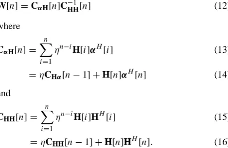
In figure 2 a measure for the channel estimate quality, the normalized mean squared error (NMSE), is given for LDPC
and Turbo Codes ofM = 4andM = 16QAM. It is calculated
by
NMSE=
N−1
P
n=0 K−1
P k=0 nT P t=1 nR P r=1
Hr,t[n, k]− ˜
Hr,t[n, k]
2
N−1
P
n=0 K−1
P k=0 nT P t=1 nR P r=1
|Hr,t[n, k]|
. (22)
The decoder algorithm implementation for LDPC codes is based on belief propagation [7], for Turbo Codes the Log-MAP algorithm is used. Both decoder approximate a-posteriori probabilities from the soft decision inputs and decide them.
For the 16-QAM modulation scheme the code rate RC was
lowered to 1/4 to match the same Eb/N0 as with 4-QAM
and RC = 1/2. It is shown that the proposed enhancement
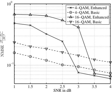
improves the channel estimate quality in terms of MSE. All solid lines, which denote the enhanced scheme, finally are below the dashed ones, which denote the basic DDCE approach, even for 16-QAM modulation which requires higher accuracy in magnitude. The minimum of MSE is reached when also the BER in figure 3 first hits its minimum, i.e. error-free transmission of 15 frames. If the transmission is not error-free, in the case the SNR is too low, the proposed scheme performs much worse than the basic algorithm. This holds in terms of MSE and BER. In this case the decoding algorithms try to determine the possibly corrupted message bits from a large portion of corrupted check bits. The iterative result may end in a decoded bit word that has a larger Hamming distance than the unprocessed message bits to the original message. This introduces even more symbol errors in RLS algorithm than the basic algorithm would. So applying this scheme at very low SNR yields no gain, even more loss. But above the threshold of virtually error-free decoding a gain in MSE can be realized.
B. DDCE schemes vs. interpolation
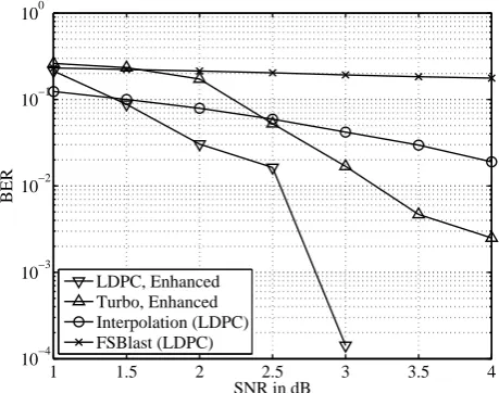
In figure 4 the bit error rates for three MIMO-OFDM systems (4-QAM modulated) and a single-carrier system are compared: First a MIMO-OFDM RLS enhanced DDCE sys-tem with LDPC Codes as channel coder, second again a RLS enhanced DDCE system with Turbo Codes consisting of two recursive systematic convolutional coder with generator
polynomials (7,5) punctured to code rate 1/2. The third is a
MIMO-OFDM system with a polynomial interpolation over distributed pilots in the time-frequency grid [8]. The last system is the FS-BLAST where the interference is canceled out successively from the MIMO layers [9]. The number of pilots is equal to the RLS DDCE systems. Furthermore, its channel code is the same as the first system’s. It is a half-rate LDPC code built from a regular parity check matrix [10].
The RLS DDCE systems clearly outperform the inter-polation and the FS-BLAST systems under the conditions considered here, SNR range, channel order and Doppler shifts.
1 1.5 2 2.5 3 3.5 4 10−1
100
SNR in dB
NMS
E
|
H
−
˜H|
2 | H | 2 4−QAM, Enhanced 4−QAM, Basic 16−QAM, Enhanced 16−QAM, Basic
Fig. 2. Channel estimation error expressed in Normalized Mean Square Error (NMSE)
1 1.5 2 2.5 3 3.5 4 10−4
10−3 10−2 10−1 100
SNR in dB
BER
LDPC, Enhanced LDPC, Basic Turbo, Enhanced Turbo, Basic
Fig. 3. BER comparison between basic DDCE and enhanced DDCE implementation for Turbo and LDPC Codes
1 1.5 2 2.5 3 3.5 4 10−4
10−3 10−2 10−1 100
SNR in dB
BER
LDPC, Enhanced Turbo, Enhanced Interpolation (LDPC) FSBlast (LDPC)
Fig. 4. BER comparison enhanced DDCE scheme with a traditional interpolation approach (LDPC coded)
Fig. 2. Channel estimation error expressed in Normalized Mean
Square Error (NMSE).
as stated in Eq. (3); the associated symbol vector of thet-th antenna is denoted with st.
The single symbol mapping or quantization operation
Q will be replaced by decisions based upon a codeword ˜
I=C−1{˜st}andsˆt=C{˜I}we can write a new quantization op-eration asQ0{·}:=C{C−1{·}}. Through the decoding and re-encoding symbol errors will be corrected and the corrected versions are used to update the channel estimate in Eqs. (8) and (9).
Therefore the estimated symbols˜st are soft demodulated. The corresponding Log-Likelihood Ratios (LLR)˜I are input of the used decoder. Both Turbo Codes’ and LDPC Codes’ decoder use LLRs. The possibly corrected decoder output must be modulated and is then equivalent to the mapped ver-sionsˆs and can be fed into the MIMO RLS algorithm. The whole scheme is visualized in Fig. 1.
However, if the noise is too high and too many errors oc-cur in a codeword the underlying decoding procedure might introduce more errors through unsuccessful iterative decod-ing than there are originally. This is in particular the case for LDPC Codes. Thus, below the threshold of a sufficiently probable correct decoding, the proposed enhancement per-forms worse than the unmodified algorithm. Only above that threshold a gain in channel estimation in terms of mean square error can be realized.
5 Simulation results
For the following results the system parameters are given in Table 1. The MIMO transmission scheme is chosen as spatial multiplexing, i.e. two independent data streams are transmit-ted over the two transmit antennas. It lies in the structure of
A. Turbo vs. LDPC Codes
In figure 2 a measure for the channel estimate quality, the normalized mean squared error (NMSE), is given for LDPC
and Turbo Codes ofM = 4andM = 16QAM. It is calculated
by
NMSE=
N−1
P
n=0 K−1
P k=0 nT P t=1 nR P r=1
Hr,t[n, k]−H˜r,t[n, k]
2
N−1
P
n=0 K−1
P k=0 nT P t=1 nR P r=1
|Hr,t[n, k]|
. (22)
The decoder algorithm implementation for LDPC codes is based on belief propagation [7], for Turbo Codes the Log-MAP algorithm is used. Both decoder approximate a-posteriori probabilities from the soft decision inputs and decide them.
For the 16-QAM modulation scheme the code rate RC was
lowered to 1/4 to match the same Eb/N0 as with 4-QAM
and RC = 1/2. It is shown that the proposed enhancement
improves the channel estimate quality in terms of MSE. All solid lines, which denote the enhanced scheme, finally are below the dashed ones, which denote the basic DDCE approach, even for 16-QAM modulation which requires higher accuracy in magnitude. The minimum of MSE is reached when also the BER in figure 3 first hits its minimum, i.e. error-free transmission of 15 frames. If the transmission is not error-free, in the case the SNR is too low, the proposed scheme performs much worse than the basic algorithm. This holds in terms of MSE and BER. In this case the decoding algorithms try to determine the possibly corrupted message bits from a large portion of corrupted check bits. The iterative result may end in a decoded bit word that has a larger Hamming distance than the unprocessed message bits to the original message. This introduces even more symbol errors in RLS algorithm than the basic algorithm would. So applying this scheme at very low SNR yields no gain, even more loss. But above the threshold of virtually error-free decoding a gain in MSE can be realized.
B. DDCE schemes vs. interpolation
In figure 4 the bit error rates for three MIMO-OFDM systems (4-QAM modulated) and a single-carrier system are compared: First a MIMO-OFDM RLS enhanced DDCE sys-tem with LDPC Codes as channel coder, second again a RLS enhanced DDCE system with Turbo Codes consisting of two recursive systematic convolutional coder with generator
polynomials (7,5) punctured to code rate 1/2. The third is a
MIMO-OFDM system with a polynomial interpolation over distributed pilots in the time-frequency grid [8]. The last system is the FS-BLAST where the interference is canceled out successively from the MIMO layers [9]. The number of pilots is equal to the RLS DDCE systems. Furthermore, its channel code is the same as the first system’s. It is a half-rate LDPC code built from a regular parity check matrix [10].
The RLS DDCE systems clearly outperform the inter-polation and the FS-BLAST systems under the conditions considered here, SNR range, channel order and Doppler shifts.
1 1.5 2 2.5 3 3.5 4 10−1
100
SNR in dB
NMS
E
|
H
−
˜H|
2 | H | 2 4−QAM, Enhanced 4−QAM, Basic 16−QAM, Enhanced 16−QAM, Basic
Fig. 2. Channel estimation error expressed in Normalized Mean Square Error (NMSE)
1 1.5 2 2.5 3 3.5 4 10−4
10−3 10−2 10−1 100
SNR in dB
BER
LDPC, Enhanced LDPC, Basic Turbo, Enhanced Turbo, Basic
Fig. 3. BER comparison between basic DDCE and enhanced DDCE implementation for Turbo and LDPC Codes
1 1.5 2 2.5 3 3.5 4 10−4
10−3 10−2 10−1 100
SNR in dB
BER
LDPC, Enhanced Turbo, Enhanced Interpolation (LDPC) FSBlast (LDPC)
Fig. 4. BER comparison enhanced DDCE scheme with a traditional interpolation approach (LDPC coded)
Fig. 3. BER comparison between basic DDCE and enhanced DDCE
implementation for Turbo and LDPC Codes.
the MIMO RLS algorithm to find an optimal combination of the four receive signals to reconstruct the transmit signals. 5.1 Turbo vs. LDPC codes
In Fig. 2 a measure for the channel estimate quality, the nor-malized mean squared error (NMSE), is given for LDPC and Turbo Codes ofM=4 andM=16 QAM. It is calculated by
NMSE= N−1 P n=0 K−1 P k=0 nT P t=1 nR P r=1
Hr,t[n, k] − ˜Hr,t[n, k] 2 N−1 P n=0 K−1 P k=0 nT P t=1 nR P r=1
Hr,t[n, k]
. (22)
The decoder algorithm implementation for LDPC codes is based on belief propagation (Pearl, 1988), for Turbo Codes the Log-MAP algorithm is used. Both decoder approximate a-posteriori probabilities from the soft decision inputs and decide them. For the 16-QAM modulation scheme the code rate RC was lowered to 1/4 to match the sameEb/N0 as with 4-QAM andRC=1/2. It is shown that the proposed enhancement improves the channel estimate quality in terms of MSE. All solid lines, which denote the enhanced scheme, finally are below the dashed ones, which denote the basic DDCE approach, even for 16-QAM modulation which re-quires higher accuracy in magnitude. The minimum of MSE is reached when also the BER in Fig. 3 first hits its minimum, i.e. error-free transmission of 15 frames. If the transmission is not error-free, in the case the SNR is too low, the proposed scheme performs much worse than the basic algorithm. This holds in terms of MSE and BER. In this case the decoding algorithms try to determine the possibly corrupted message bits from a large portion of corrupted check bits. The iter-ative result may end in a decoded bit word that has a larger
P. Beinschob et al.: Improving MIMO-OFDM decision-directed channel estimation 87
Table 1. MIMO-OFDM system parameters.
NT×NR 2×4
number of subcarriersK 128
samples of guard interval 8
number of OFDM symbols per frame 256
number of training symbols 128
channel model COST207 BU
channel orderL 8
bandwidth 12.5 MHz
carrier frequency 2.412 GHz
normalized Doppler frequencyfd,n 0.0018921
terminal velocityv 77 km/h
Hamming distance than the unprocessed message bits to the original message. This introduces even more symbol errors in RLS algorithm than the basic algorithm would. So apply-ing this scheme at very low SNR yields no gain, even more loss. But above the threshold of virtually error-free decoding a gain in MSE can be realized.
5.2 DDCE schemes vs. interpolation
In Fig. 4 the bit error rates for three MIMO-OFDM systems (4-QAM modulated) and a single-carrier system are com-pared: First a MIMO-OFDM RLS enhanced DDCE sys-tem with LDPC Codes as channel coder, second again a RLS enhanced DDCE system with Turbo Codes consisting of two recursive systematic convolutional coder with gener-ator polynomials(7,5)punctured to code rate 1/2. The third is a MIMO-OFDM system with a polynomial interpolation over distributed pilots in the time-frequency grid (Lieberei and Z¨olzer, 2008). The last system is the FS-BLAST where the interference is canceled out successively from the MIMO layers (Weikert, 2007). The number of pilots is equal to the RLS DDCE systems. Furthermore, its channel code is the same as the first system’s. It is a half-rate LDPC code built from a regular parity check matrix (MacKay, 1999).
The RLS DDCE systems clearly outperform the interpo-lation and the FS-BLAST systems under the conditions con-sidered here, SNR range, channel order and Doppler shifts. 5.3 Future work
For the simulations LDPC codes where generated using a regular parity check matrix. Recent results have shown that irregular parity check matrices have even better error-correcting properties (Luby et al., 1997). So additional im-provements can be made if these codes are used. However, the code word length has impact on the performance. In the presented system a larger code word would need more subcarriers thus means a longer OFDM symbol duration. A larger OFDM symbol duration would decrease the ability
A. Turbo vs. LDPC Codes
In figure 2 a measure for the channel estimate quality, the normalized mean squared error (NMSE), is given for LDPC
and Turbo Codes ofM = 4andM = 16QAM. It is calculated
by
NMSE=
N−1
P
n=0 K−1
P
k=0 nT
P
t=1 nR
P
r=1
Hr,t[n, k]−H˜r,t[n, k]
2
N−1
P
n=0 K−1
P
k=0 nT
P
t=1 nR
P
r=1
|Hr,t[n, k]|
. (22)
The decoder algorithm implementation for LDPC codes is based on belief propagation [7], for Turbo Codes the Log-MAP algorithm is used. Both decoder approximate a-posteriori probabilities from the soft decision inputs and decide them.
For the 16-QAM modulation scheme the code rate RC was
lowered to 1/4 to match the same Eb/N0 as with 4-QAM
and RC = 1/2. It is shown that the proposed enhancement
improves the channel estimate quality in terms of MSE. All solid lines, which denote the enhanced scheme, finally are below the dashed ones, which denote the basic DDCE approach, even for 16-QAM modulation which requires higher accuracy in magnitude. The minimum of MSE is reached when also the BER in figure 3 first hits its minimum, i.e. error-free transmission of 15 frames. If the transmission is not error-free, in the case the SNR is too low, the proposed scheme performs much worse than the basic algorithm. This holds in terms of MSE and BER. In this case the decoding algorithms try to determine the possibly corrupted message bits from a large portion of corrupted check bits. The iterative result may end in a decoded bit word that has a larger Hamming distance than the unprocessed message bits to the original message. This introduces even more symbol errors in RLS algorithm than the basic algorithm would. So applying this scheme at very low SNR yields no gain, even more loss. But above the threshold of virtually error-free decoding a gain in MSE can be realized.
B. DDCE schemes vs. interpolation
In figure 4 the bit error rates for three MIMO-OFDM systems (4-QAM modulated) and a single-carrier system are compared: First a MIMO-OFDM RLS enhanced DDCE sys-tem with LDPC Codes as channel coder, second again a RLS enhanced DDCE system with Turbo Codes consisting of two recursive systematic convolutional coder with generator
polynomials(7,5)punctured to code rate 1/2. The third is a
MIMO-OFDM system with a polynomial interpolation over distributed pilots in the time-frequency grid [8]. The last system is the FS-BLAST where the interference is canceled out successively from the MIMO layers [9]. The number of pilots is equal to the RLS DDCE systems. Furthermore, its channel code is the same as the first system’s. It is a half-rate LDPC code built from a regular parity check matrix [10].
The RLS DDCE systems clearly outperform the inter-polation and the FS-BLAST systems under the conditions considered here, SNR range, channel order and Doppler shifts.
1 1.5 2 2.5 3 3.5 4 10−1
100
SNR in dB
NMS
E
|
H
−
˜H|
2
|
H
|
2
4−QAM, Enhanced 4−QAM, Basic 16−QAM, Enhanced 16−QAM, Basic
Fig. 2. Channel estimation error expressed in Normalized Mean Square Error (NMSE)
1 1.5 2 2.5 3 3.5 4 10−4
10−3 10−2 10−1 100
SNR in dB
BER
LDPC, Enhanced LDPC, Basic Turbo, Enhanced Turbo, Basic
Fig. 3. BER comparison between basic DDCE and enhanced DDCE implementation for Turbo and LDPC Codes
1 1.5 2 2.5 3 3.5 4 10−4
10−3 10−2 10−1 100
SNR in dB
BER
LDPC, Enhanced Turbo, Enhanced Interpolation (LDPC) FSBlast (LDPC)
Fig. 4. BER comparison enhanced DDCE scheme with a traditional interpolation approach (LDPC coded)Fig. 4. BER comparison enhanced DDCE scheme with a traditional
interpolation approach (LDPC coded).
to track a time-varying channel. So short and yet powerful LDPC Codes are highly desirable.
6 Conclusions
A channel tracking algorithm is extended for a DDCE that uses a channel decoder/encoder as a symbol quantizer. It is feasible for the algorithm to recover from errors through the error-correcting properties of the codes. This results in significant lower failure rate due to error propagation. A threshold in SNR can be determined which depends on the error-correcting performance of the applied code. Above this threshold, the proposed DDCE code enhancement improves the channel estimate and bit error rate that verifies the chan-nel estimate. But it is limited due to the decoding operation a OFDM symbol must hold a complete code word. Below the threshold the system’s performance is degraded by the pro-posed scheme. The choice of channel coder has impact on the overall performance.
Even LDPC Codes from regular parity check matrices out-performs widespread Turbo Codes in this context. Addition-ally the MIMO-RLS scheme is compared to an interpolation approach where the noise averaging ability of the RLS leads to a better bit error rate.
References
Akhtman, J. and Hanzo, L.: Advanced Channel Estimation for MIMO-OFDM in Realistic Channel Conditions, IEEE Interna-tional Conference on Communications (ICC), 2528–2533, 24–28 June, 2007.
P¨atzold, M.: Mobilfunkkan¨ale, Vieweg Verlag, 1st Edition, 1999.
88 P. Beinschob et al.: Improving MIMO-OFDM decision-directed channel estimation
Chu, D. C.: Polyphase Codes with Good Periodic Correlation Prop-erties, IEEE Transactions on Information Theory, 18(4), 531– 532, 1972.
Haykin, S.: Adaptive Filter Theory, Prentice Hall, 4th Edition, 2001.
Yang, B.: Projection Approximation Subspace Tracking, IEEE Transactions on Signal Processing, 43(1), 95–107, 1995. Schafhuber, D. and Matz, G.: MMSE and adaptive prediction of
time-varying channels for OFDM systems, IEEE Transactions on Wireless Communications, 4(2), 593–602, 2005.
Pearl, J.: Probabilistic reasoning in intelligent systems: Networks of plausible inference, Kaufmann, 1988.
Lieberei, M. and Z¨olzer, U.: MIMO-OFDM on a Flexible Labo-ratory Radio System, International Symposium on Communi-cations, Control and Signal Processing (ISCCSP), 1184–1187, 2008.
Weikert, O.: Blinde Demodulation in
MIMO-¨
Ubertragungssystemen, Dissertation,
Helmut-Schmidt-Universit¨at, 2007.
MacKay, D. J. C.: Good error-correcting codes based on very sparse matrices, IEEE Transactions on Information Theory, 45(2), 399– 431, 1999.
Luby, M., Mitzenmachen, M., Shokrollahi, A., Spielman, D., and Stemann, V.: Practical Loss-Resilient Codes, Proceedings of the 29th annual ACM Symposium on Theory of Computing, 150– 159, 1997.