*Corresponding author:Abhinav Shukla ISSN: 0976-3031
Research Article
ANFIS BASED MANAGEMENT OF HYBRID RENEWABLE ENERGY SOURCE
IN SMART BUILDING
Abhinav Shukla
1and Neelam Sahu
21
Department of IT, Scholar, Dr. C.V. Raman University, Bilaspur, India
2Department of IT, Dr. C.V. Raman University, Bilaspur, India
DOI: http://dx.doi.org/10.24327/ijrsr.2018.0910.2790
ARTICLE INFO ABSTRACT
The presentation of the SCADA system and its use as a management software of hybrid sources is presented. Here an energy management technique for Hybrid Renewable Energy System (HRES) connected with AC load using Adaptive Neuro Fuzzy Interference System (ANFIS) is proposed. In this work, photovoltaic (PV) system, Wind Generating System (WGS), Fuel Cell (FC), Ultra Capacitor (UC) and the battery are considered as the energy sources. The ANFIS technique is trained with the inputs such as the previous instant energy of the available sources and the required load demand of the current time and the corresponding target reference power of the sources and storage devices. According to the load variation, the proposed method makes the appropriate control signals at the testing time to manage the energy of the HRES. Energy management in Smart Home environment is one of the main topics adopted in Smart Grid research field. In this paper, we present a Multi-Agent System (MAS) for a Smart Home intelligent control. Such a solution was integrated in a smart meter in order to alter the shape of the residential load curve. The MAS is strong appropriate to solve complex distributed problems as home automation system. Our contribution consists in performing an algorithm for scheduling appliances tasks, and designing a model for a direct load control which may accommodate customer preferences. A STATCOM based voltage regulation and harmonic mitigation is introduced. The implementation of the system elements and control method has been done in MATLAB/Simulink and the performance of the proposed method is analysed by using different environmental and load test conditions. The results of the test cases confirms that the proposed control technique is effective in prediction of energy required for the next instant and manages the energy flow among HRES power sources and energy storage devices.
INTRODUCTION
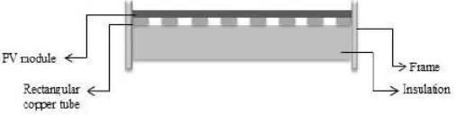
Renewable energy conversion systems are focused mainly on one type of energy processed, eg. heat or electricity. The main disadvantage of these sources is the strong dependence of the amount of energy produced by the current weather conditions and climate. From the perspective of the final user is quite troublesome. In this case, a good solution is to use a hybrid sources, for example PV/T (Photovoltaic Thermal Hybrid Solar Collectors), which shown in Fig. 1.
Fig 1 Cross-section of the PV/T module
The device combines the advantages of a photovoltaic cell with standard solar collector. Standard PV module efficiency decreases when the temperature is increasing. This phenomenon is unfavourable. PV/T modules limit decrease electrical efficiency because the heat is dissipated through the solar panel. This heat has a very good parameters and can therefore be used to keep temperature of eg. domestic hot water at the appropriate level. This solution significantly improves the economic balance of the entire investment.
The development of a home automation system based MAS has been used by many scientists. Some researchers are concentrated only on the control of an intelligent building. Others researchers are interested in the users comfort without arguing the percentage of energy reduced by their methods. Scientists have designed a Multi-Agent Home Automation system (MAHAS) and have concentrated in the user comfort without achieving a signification reduction in energy
International Journal of
Recent Scientific
Research
International Journal of Recent Scientific Research
Vol. 9, Issue, 10(A), pp. 29090-29097, October, 2018
Copyright © Abhinav Shukla and Neelam Sahu, 2018, this is an open-access article distributed under the terms of the Creative Commons Attribution License, which permits unrestricted use, distribution and reproduction in any medium, provided the original work is properly cited.
DOI: 10.24327/IJRSR
CODEN: IJRSFP (USA)
Article History: Received 4th July, 2018 Received in revised form 25th August, 2018
Accepted 23rd September, 2018 Published online 28th October, 2018
Key Words:
Abhinav Shukla and Neelam Sahu
consumption. Developing MAS is not restricted to modelling intelligent building, but must contain a learning ability and dynamically learning new behaviours, to suit the residential preferences.
ANFIS is very close to human reasoning and affords an easy and efficient control with minimum analytical developments. Studies are done in the control of building using ANFIS, but some of them are concentrated only on the control or energy consumption without providing comfort to their residents. A HVAC system was controlled also by an adaptive hierarchical fuzzy controller with two level. This hierarchical ANFIS aims to improve the resident comfort level within a thermal space control.
In a PV generating system, an adaptive neuro
system (ANFIS) based MPPT control is employed to predict voltage for maximum power operation using short circuit current and open circuit voltage as inputs. Root mean square error (RMSE) is used to tune the best membership functions in FIS structure. ANFIS-based supervisory control system takes the power demanded by the grid, the available renewable power, the hydrogen tank level and the SOC of the battery as inputs and determines the power that are supplied by/stored in the FC and battery. Another ANFIS-based control is a applied to the three-phase inverter, which controls the power delivered by HPS to grid by controlling the active and reactive power. Load frequency control of Multi-area power system network is achieved by ANFIS controller.
The parameters of the static synchronous compensator (STATCOM) are tuned for proper reactive power requirement and to stabilize voltage using ANFIS based approach with disturbances in load and power generation of a wind HPS. The transient responses of HPS are compared under DC link capacitor and dynamic compensation by STATCOM. The review of the recent research work shows that, energy management of hybrid renewable energy, storage devices for micro-grids require an intelligent controller. Many techniques are used for the energy management strategies such as fuzzy, neuro-fuzzy and optimization algorithms. Accordingly, a hybrid renewable energy system’s control strategies are designed to achieve the goal of meeting load demand, by the use of energy sources optimally and to regulate the voltage and frequency of AC bus. Therefore, an integrated renewable energy system with an intelligent energy management is required for a promising solution to overcome this challenge. ANFIS based EMS is not found applied for standalone HPS any of the literature.
This paper proposes an energy management system for the standalone HPS using ANFIS technique. The ANFIS technique is trained with the inputs such as the previous instant energy of the available sources, the required load demand
time and the corresponding target reference power of the sources are determined. According to the load variation, the proposed method makes the appropriate control signals at the testing time to match the source power and load power. The primary novelties of the control schemes employed in this paper are:
1) the application of ANFIS to the EMS of a standalone HRES, which generates reference powers for ESS (Fuel Cell, battery and UC) that are generated by/stored in the ESS, taking into
Abhinav Shukla and Neelam Sahu., Anfis Based Management of Hybrid Renewable Energy Source In Smart Building
consumption. Developing MAS is not restricted to modelling intelligent building, but must contain a learning ability and dynamically learning new behaviours, to suit the residential
ANFIS is very close to human reasoning and affords an easy and efficient control with minimum analytical developments. Studies are done in the control of building using ANFIS, but some of them are concentrated only on the control or energy consumption without providing comfort to their residents. A s controlled also by an adaptive hierarchical fuzzy controller with two level. This hierarchical ANFIS aims to improve the resident comfort level within a thermal space
In a PV generating system, an adaptive neuro-fuzzy inference ased MPPT control is employed to predict voltage for maximum power operation using short circuit current and open circuit voltage as inputs. Root mean square error (RMSE) is used to tune the best membership functions in ry control system takes the power demanded by the grid, the available renewable power, the hydrogen tank level and the SOC of the battery as inputs and determines the power that are supplied by/stored in based control is also phase inverter, which controls the power delivered by HPS to grid by controlling the active and reactive area power system
tic synchronous compensator (STATCOM) are tuned for proper reactive power requirement and to stabilize voltage using ANFIS based approach with disturbances in load and power generation of a wind-diesel HPS. The transient responses of HPS are compared under fixed DC link capacitor and dynamic compensation by STATCOM. The review of the recent research work shows that, energy management of hybrid renewable energy, storage devices for grids require an intelligent controller. Many techniques the energy management strategies such as fuzzy, fuzzy and optimization algorithms. Accordingly, a hybrid renewable energy system’s control strategies are designed to achieve the goal of meeting load demand, by the to regulate the voltage and frequency of AC bus. Therefore, an integrated renewable energy system with an intelligent energy management is required for a promising solution to overcome this challenge. ANFIS based EMS is not found applied for standalone HPS in
This paper proposes an energy management system for the standalone HPS using ANFIS technique. The ANFIS technique is trained with the inputs such as the previous instant energy of the available sources, the required load demand of the current time and the corresponding target reference power of the sources are determined. According to the load variation, the proposed method makes the appropriate control signals at the testing time to match the source power and load power. The imary novelties of the control schemes employed in this
application of ANFIS to the EMS of a standalone HRES, which generates reference powers for ESS (Fuel Cell, battery and UC) that are generated by/stored in the ESS, taking into
account previous instant power of the renewable sources and the load demand of the current instant and 2) harmonic mitigation and voltage regulation in ac bus is achieved by the STATCOM.
General Data Modeling Process
The five techniques that are introduced in the previous section as reference are used in order to train the energy consumption prediction of buildings, looking for the optimal configuration of their hyper parameters. For this purpose, we use the R13 package named CARET14. This package is a set of functions that attempts to streamline the process for creating predictive models. The five techniques implemented in R enable us to adjust their tuning parameters.
Intelligent buildings - control theory
The essence of Building Management Systems and Intelligent Buildings is in the control technologies, which allow integration, automation, and optimisation of all the services and equipment that provide services and manages the environment of the building concerned. Programmable Logic Controllers (PLC's) formed the original basis of the control technologies. Later developments, in commercial and residential applications, were based on 'distributed
microprocessors'.
The use of these technologies all
various site and building services, often yielding significant cost reductions and large energy savings.
Model Based Control
Our strategy to develop models that support building design and real‐time operation is two
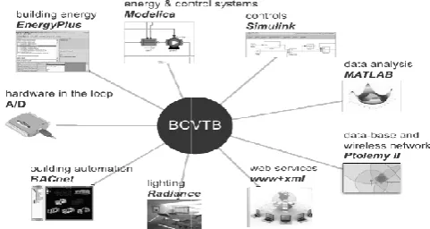
Building Controls Virtual Test Bed (BCVTB) (Wetter, 2011), users can close control loops across existing
connect them to control systems for two
(Fig.2). Through MATLAB software, local and supervisory control systems can be modelled, including dynamic response of HVAC equipment. These models are modular to allow subsystem models to be embedded in next
information systems and model
Fig 2 Building Controls Virtual Test Bed with interfaces to programs and
control systems
Closing control loops with the BCVTB allows, for example, the development and performance assessment of closed control algorithms, implemented in MATLAB or Modelica, that integrate light‐redirecting façade elements, implemented as a Radiance model, with HVAC loads, computed by Energy Plus. This coupling across simulators and control systems has been used to develop supervisory control sequences for
Anfis Based Management of Hybrid Renewable Energy Source In Smart Building
unt previous instant power of the renewable sources and the load demand of the current instant and 2) harmonic mitigation and voltage regulation in ac bus is achieved by the
General Data Modeling Process
The five techniques that are introduced in the previous section as reference are used in order to train the energy consumption prediction of buildings, looking for the optimal configuration of their hyper parameters. For this purpose, we use the R13 e named CARET14. This package is a set of functions that attempts to streamline the process for creating predictive models. The five techniques implemented in R enable us to adjust their tuning parameters.
control theory
essence of Building Management Systems and Intelligent Buildings is in the control technologies, which allow integration, automation, and optimisation of all the services and equipment that provide services and manages the environment rned. Programmable Logic Controllers (PLC's) formed the original basis of the control technologies. Later developments, in commercial and residential applications, were based on 'distributed-intelligence
The use of these technologies allows the optimisation of various site and building services, often yielding significant cost reductions and large energy savings.
strategy to develop models that support buildingcontrols time operation is two‐fold. Through the Virtual Test Bed (BCVTB) (Wetter, 2011), users can close control loops across existing simulators, and connect them to control systems for two‐way communication (Fig.2). Through MATLAB software, local and supervisory
l systems can be modelled, including dynamic response of HVAC equipment. These models are modular to allow subsystem models to be embedded in next‐generation energy information systems and model‐based control algorithms.
Building Controls Virtual Test Bed with interfaces to programs and control systems
facades, lighting systems and HVAC systems. It has also been used for real‐time performance comparison relative to a building model that represents design‐intent.
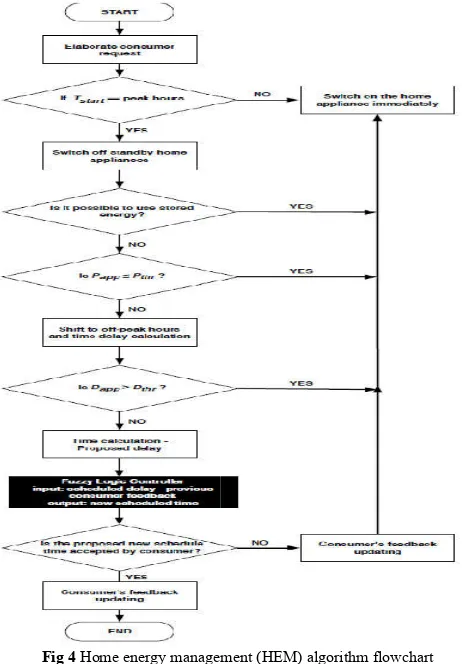
ANFIS for Home Energy Management
The proposed ANFIS monitors and controls the electrical appliances in the smart home, planning a convenient start time for them. The flowchart of the proposed HEM algorithm is shown in Fig.3. The starting point is represented by the time instant in which the consumer turns on an appliance (T this time, a proper signal is sent to the EMU in order to notify about this operation. Subsequently, the EMU interacts both with the smart meter and with the storage system in order to know about the TOU prices. As a consequence, the EMU is able to known the corresponding energy consumption prices at that particular moment and then can easily check whether the current time falls within peak hours. In the next step, the EMU verifies if the starting time of the appliance (T
the peak hours. If so, the EMU allows the appliance to start immediately; otherwise, the algorithm moves to the next step, because Tstart is in peak hours. Considering that even standby
appliances play a reasonable role in energy wastage, in the next step, the EMU checks for all of the standby appliances in home and turns them all off, regardless of their requests to be turned on. Subsequently, the EMU communicates with the local energy storage system in order to inquire abo
generated or stored energy. As a consequence, if there is enough energy in the storage system for the appliance, it is started immediately, without any delay. On the contrary, the algorithm goes ahead Energies 2015, 8 11926 to the next step where a comparison between the power ratings is carried out. In fact, considering that in the proposed scheme, a threshold value of power (Pthr) is set, the EMU evaluates the power rating
of the i-th appliance (Papp), and for every appliance request, its
power rating is compared to the threshold value (P
Pthr, then the appliance can start immediately; otherwise, the
algorithm moves to the next step.
In this case, the appliance operation is shifted from peak hours to off-peak ones. As a result, a delay (D
difference of the scheduled time suggested by the EMU and the request start time, is introduced in the operation of the appliance cycle due to the load shifting technique. It is necessary to note that this delay can be inversely proportional to the comfort level desired by the consumers. In fact, large delays can significantly lower their satisfaction. For this reason, in the proposed scheme, a threshold value of delay (D been taken into account. Each device has its threshold value of delay In fact, in the next step of the algorithm, a comparison between the delays is carried out. If Dapp
appliance can start immediately. The algorithm moves ahead in the next step if the previous condition is not s
consequence, the appliance cycle is shifted to hours where electricity prices are comparatively low.
calculates the delay in the appliance cycle and sends it to the appliance in order to make it known what will be its start tim The scheduled time (delay) is calculated from the difference between the starting time of the appliance scheduled by the EMU and the request start time by the appliance.
stems and HVAC systems. It has also been time performance comparison relative to a
The proposed ANFIS monitors and controls the electrical appliances in the smart home, planning a convenient start time flowchart of the proposed HEM algorithm is starting point is represented by the time the consumer turns on an appliance (Tstart). At
this time, a proper signal is sent to the EMU in order to notify about this operation. Subsequently, the EMU interacts both with the smart meter and with the storage system in order to es. As a consequence, the EMU is able to known the corresponding energy consumption prices at that particular moment and then can easily check whether the current time falls within peak hours. In the next step, the EMU appliance (Tstart) falls outside
the peak hours. If so, the EMU allows the appliance to start immediately; otherwise, the algorithm moves to the next step, is in peak hours. Considering that even standby energy wastage, in the next step, the EMU checks for all of the standby appliances in home and turns them all off, regardless of their requests to be turned on. Subsequently, the EMU communicates with the local energy storage system in order to inquire about the locally-generated or stored energy. As a consequence, if there is enough energy in the storage system for the appliance, it is started immediately, without any delay. On the contrary, the 11926 to the next step where a comparison between the power ratings is carried out. In fact, considering that in the proposed scheme, a threshold ) is set, the EMU evaluates the power rating ), and for every appliance request, its ower rating is compared to the threshold value (Pthr). If Papp ≤
, then the appliance can start immediately; otherwise, the
In this case, the appliance operation is shifted from peak hours result, a delay (Dapp), equal to the
difference of the scheduled time suggested by the EMU and the request start time, is introduced in the operation of the appliance cycle due to the load shifting technique. It is inversely proportional to the comfort level desired by the consumers. In fact, large delays can significantly lower their satisfaction. For this reason, in the proposed scheme, a threshold value of delay (Dthr) has
its threshold value of In fact, in the next step of the algorithm, a comparison
app > Dthr, then the
The algorithm moves ahead in the next step if the previous condition is not satisfied. As a consequence, the appliance cycle is shifted to hours where Then, the EMU calculates the delay in the appliance cycle and sends it to the it known what will be its start time. The scheduled time (delay) is calculated from the difference the starting time of the appliance scheduled by the EMU and the request start time by the appliance.
Hybrid Renewable Energy System with Proposed Energy Management Scheme
The HRES structure with proposed methodology is depicted in Fig.5. The presented HRES is identified as three groups and they are connected to DC bus commonly. The first group consists of the renewable energy sources, solar PV system and WECS, which provides power
wind or solar resources available. The second group encompasses the energy storage systems, battery, UC and FC, which offers the durable electrical energy as well as the fast dynamic power regulation. Finally, the VSI delivers t
and the reactive power to the AC load
bus power. The model of renewable energy sources, energy storage devices and proposed energy management system are described in the following subsections.
Fig 4 Home energy managemen
Hybrid Renewable Energy System with Proposed Energy
structure with proposed methodology is depicted in Fig.5. The presented HRES is identified as three groups and they are connected to DC bus commonly. The first group consists of the renewable energy sources, solar PV system and WECS, which provides power to the DC bus when there is wind or solar resources available. The second group encompasses the energy storage systems, battery, UC and FC, which offers the durable electrical energy as well as the fast dynamic power regulation. Finally, the VSI delivers the active and the reactive power to the AC load-connected, using the DC bus power. The model of renewable energy sources, energy storage devices and proposed energy management system are described in the following subsections.
Home energy management (HEM) algorithm flowchart
Abhinav Shukla and Neelam Sahu
Fig 5 Structure of the HRES with proposed methodology
PV System
The PV system constitutes one of the renewable energy sources in HPS, which extort the power from the existing solar energy. The energy management system needs to operate at maximum power from the PV system when the load demand is greater than the accessible power generation and need to operate with controlled power from the PV system when the load demand is within the accessible generation power. In this system, the traditional Perturb and Observation (P&O) Maximum Power Point algorithm is elegantly employed.
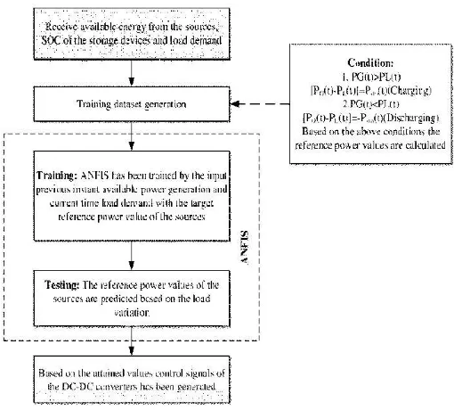
Training Dataset Generation
The responsibility of energy management system is to utilize the energy sources of the HRES and control the energy storage devices with the intention of providing the power demanded by the load/grid. The proposed ANFIS technique requires suitable training data set for managing the HRES. The required energy management training dataset has been developed as per the available generation from the sources of HPS and the load demand at particular instant. The training dataset d
reference power required from the renewable energy sources and the storage devices. The source power can be described by
( ) = ( ) + ( )
Where, ( ) represents the total power generated from the available renewable energy sources at time t;
( )symbolizes the total power of the available sources in the HRES at time t and ( ) signifies the total power from the storage devices at time. The renewable energy sources and the storage devices power are described by means of given Eq.
( ) = ( ) + ( )
( ) = ( ) + ( ) + ( )
Where, ( ) represents the power generated from the PV system at time t ; ( )characterizes the power generated from the wind turbine at time t ; ( )signifies the power required from the battery at time t ; ( )relates to the power required from the UC at time t and ( )
power required from the FC at time t .
ANFIS based Energy Management Scheme
The ANFIS has emerged as a hybrid soft computing technique, involving the blend of the neural network and fuzzy, utilising superior level reasoning skills and inferior level computational command. ANFIS is a powerful adaptive network for modelling complex and nonlinear systems with less input and the output target parameters. The fuzzy interference system is
Abhinav Shukla and Neelam Sahu., Anfis Based Management of Hybrid Renewable Energy Source In Smart Building
Structure of the HRES with proposed methodology
The PV system constitutes one of the renewable energy sources in HPS, which extort the power from the existing solar energy. The energy management system needs to operate at maximum power from the PV system when the load demand is greater le power generation and need to operate with controlled power from the PV system when the load demand is within the accessible generation power. In this system, the traditional Perturb and Observation (P&O) Maximum Power
The responsibility of energy management system is to utilize the energy sources of the HRES and control the energy storage devices with the intention of providing the power demanded by echnique requires suitable training data set for managing the HRES. The required energy management training dataset has been developed as per the available generation from the sources of HPS and the load demand at particular instant. The training dataset decides the reference power required from the renewable energy sources and the storage devices. The source power can be described by
represents the total power generated from the available renewable energy sources at time t; symbolizes the total power of the available sources in signifies the total power from e renewable energy sources and the storage devices power are described by means of given Eq.
represents the power generated from the PV characterizes the power generated
( )signifies the power
( )relates to the power
( )corresponds to the
ANFIS based Energy Management Scheme
The ANFIS has emerged as a hybrid soft computing technique, involving the blend of the neural network and fuzzy, utilising inferior level computational command. ANFIS is a powerful adaptive network for modelling complex and nonlinear systems with less input and the output target parameters. The fuzzy interference system is
fine-tuned by the neural network learning technique. uses hybrid learning procedure, to form input relationship based on the human knowledge and input data. Normally, the ANFIS is home to a layered structure, which is well-illustrated in Fig.6. It embraces five functional nodes such as input, fuzzification, product, normalization and defuzzification nodes. The square nodes are the adaptive nodes and the circle nodes are the fixed nodes. The inputs for ANFIS are the previous instant power generation from the renewable energy sources ( − 1)and the load demand
output target is reference power of the HRES
employing the relative parameters, the novel ANFIS technique is able to generate the rules and tuned efficiently. It has one output, the reference power
storage devices. The reference powers for battery, fuel cell, and ultra capacitor are calculated by using SOC limitations for each device and SOC levels. A common rule set for the first order Takagi-Sugeno interference system
described.
Rule 1: If ( − 1)
( − 1) + ( ) +
Rule 2: If ( − 1)
( − 1) + ( ) +
Where, , , , , , , , , characterize the non
levels relating to the fuzzy rules can be calculated by means of the relation = ( )∎
“and” can be optimized by a permanent t
each rule is obtained as a linear blend between parameters of the antecedents of each rule.
= ( − 1) + ( ) +
Fig.6 Structure of the ANFIS
Fig.7 shows the fuzzy reasoning of the ANFIS
The output of the model is
standardized activation degrees of the rules by the individual output of each rule, which is furnished in Eq..
=∑
∑ , = 1,2, …
Anfis Based Management of Hybrid Renewable Energy Source In Smart Building
tuned by the neural network learning technique. ANFIS uses hybrid learning procedure, to form input-output relationship based on the human knowledge and input-output Normally, the ANFIS is home to a layered structure, illustrated in Fig.6. It embraces five functional put, fuzzification, product, normalization and defuzzification nodes. The square nodes are the adaptive nodes and the circle nodes are the fixed nodes. The inputs for ANFIS are the previous instant power generation from the renewable and the load demand ( )and the output target is reference power of the HRES ( ). By employing the relative parameters, the novel ANFIS technique is able to generate the rules and tuned efficiently. It has one output, the reference power that must be generated from storage devices. The reference powers for battery, fuel cell, and ultra capacitor are calculated by using SOC limitations for each device and SOC levels. A common rule set for the first order Sugeno interference system with two fuzzy layers is
) ( ) then =
) ( ) then =
represent the linear parameters, characterize the non-linear parameters. Activation levels relating to the fuzzy rules can be calculated by means of
( ) where the logical operator “and” can be optimized by a permanent t-norm. The output of each rule is obtained as a linear blend between parameters of
( ) + , = 1,2 …
Structure of the ANFIS
shows the fuzzy reasoning of the ANFIS
Where, represents the normalized value, which constitutes the sum of and . The ANFIS layer framework is beautifully pictured in Fig.2 and the related depiction is furnished as follows.
Fuzzification layer
In the fuzzification layer each and every input layer characterizes an input variable which is furnished into fuzzification layer. The generated power at previous instant
( − 1) and the load demand at the current instant ( )of
nodes are represented by , , , , in which , , ,
constitute the linguistic labels of fuzzy theory for dividing the membership functions. The output of the fuzzy layers are:
, = ( − 1) , = 1,2
, = ( ) , = 1,2
Where, , and , represent the output of the fuzzy layer
and ( − 1) and ( ) characterize the
membership function of the fuzzy layer.
Product layer
The product layer gracefully discharges the task of carrying out the logical “and” or product of the input membership functions. The product layer output signifies the input weight function of the succeeding node. The output of this layer can be described by the equations.
= , = ( − 1) . ( ) , = 1,2
= , = ( − 1) . ( ) , = 1,2
Where, represent the outputs of the product layer.
Normalization layer
The normalized layer represents the third layer, where each node is a permanent one which characterizes the IF segment of a fuzzy rule. It is effectively employed to normalize the input weights, and is competent to carry out the fuzzy “and” operation. This layer may be labeled as N and the output of the corresponding layer is expressed in equations.
= , =
+ , = 1,2;
= , =
+ , = 1,2;
Where, represent the outputs of the normalized layer.
Defuzzification layer
The task assigned to this layer is the execution of an adaptive function, which furnishes output membership function in accordance with the preset fuzzy rules. The output of the defuzzification layer is furnished by means of Equations.
= , =
+ [ ( − 1) + ( ) + ]
= , =
+ [ ( − 1) + ( ) + ]
Where, are the outputs of the de-fuzzy layer.
Total output layer
The output layer characterizes the THEN segment of the fuzzy rule. The sum of the input signals may be calculated, which is
furnished as∑ . The total output of the layer is furnished by Eq.
= , = =
∑ ∑
Where, represents the total output. When the ANFIS training is finished, it is ready to give the reference power ( ) to manage the energy of the HRES. By using the proposed method, the PV, WECS, FC, UC and battery controller are taking decisions and the power exchange between the source and load side is enhanced. The proposed methodology energy management structure is shown in the following Fig.8. The references for various systems in HRES are generated based on the equations. The proposed energy management technique is implemented in the MATLAB/Simulink platform and the effectiveness is tested for two different cases.
Fig 8 Structure of the proposed energy management
Power Quality Improvement
In this paper a Synchronous Static Compensator (STATCOM) is employed for the voltage regulation and to compensate the harmonics. It is a class of Voltage Source Converter based FACTS device which is a controlled reactive power source consisting of a VSI. It is a shunt connected device used for voltage control, power factor correction, load balancing and harmonics compensation by providing reactive power.
RESULTS AND DISCUSSION
The proposed energy management is designed for the HRES system in Fig.9 and the effectiveness of the proposed method is analysed in two test cases. The designed model of the HRES configuration is described in Table 1.
Abhinav Shukla and Neelam Sahu., Anfis Based Management of Hybrid Renewable Energy Source In Smart Building
Table 1 Simulation parameters of HPS
The proposed method’s effectiveness is verified through two different test cases like input power generation variation and output load variation. Initially the proposed method is verified through the input power generation variation but the load value is constant 6 kW nonlinear load (diode rectifier with R load). The required reference load demand is described in Fig.9. According to the first test case, the irradiation of the PV system is shown in Fig.10. Based on the irradiation level, the output power generated from the PV is described in Fig.11. The output power of the PV generator is varied between 1.6 kW to 3.6 kW. The maximum power of the PV is extracted at the period 0.25 to 0.85 s and 2 to 3 s. The minimum power generation is attained at the period 1.25 to 1.5 s. At this time, the required load demand is satisfied by utilizing PV, WT output power and storage devices output power. The MPPT of the PV generation system is attained from the traditional P&O technique.
Fig. 9 PV generator output power
Fig.10 WT output power
Fig.11 FC output power
Fig 12 FC (a) current (b) voltage
Fig.13 UC output power
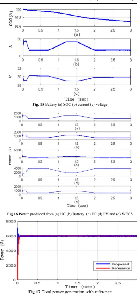
Fig. 15 Battery (a) SOC (b) current (c) voltage
.
Fig.16 Power produced from (a) UC (b) Battery (c) FC (d) PV and (e) WECS
Fig 17 Total power generation with reference
The generated power from the WT is illustrated in Fig.12. The MPPT of the WT is attained by using the traditional P& MPPT technique. The FC output power utilized for the testing condition is described in Fig.13. It shows that the fuel cell power utilization is increased from the period 1.25 to 1.5 s, during which the reduced power generation from the PV system. The FC voltage and current are described in Fig.14. The UC output power based on the load demand and input available power generation is described in Fig.15. The maximum power discharged from the UC during the time period 1.25 to 1.5 s and after that constant pow
from the UC. The power of the UC is 550 W at 0.25 to 0.85 s and 2 to 3 s. The voltage, current and state of charge (SOC) of UC are described in Fig.16. It is clearly shows that the SOC of the UC is reduced from the 92% to 90% from the peri
3 s. The battery power utilized by the energy management scheme is shown in Fig.17. The battery SOC, current and voltage are illustrated in Fig. 18. The final power outcome of
voltage
Power produced from (a) UC (b) Battery (c) FC (d) PV and (e) WECS
Total power generation with reference
The generated power from the WT is illustrated in Fig.12. The MPPT of the WT is attained by using the traditional P&O MPPT technique. The FC output power utilized for the testing condition is described in Fig.13. It shows that the fuel cell power utilization is increased from the period 1.25 to 1.5 s, during which the reduced power generation from the PV voltage and current are described in Fig.14. The UC output power based on the load demand and input available power generation is described in Fig.15. The maximum power discharged from the UC during the time period 1.25 to 1.5 s and after that constant power only utilized from the UC. The power of the UC is 550 W at 0.25 to 0.85 s and 2 to 3 s. The voltage, current and state of charge (SOC) of UC are described in Fig.16. It is clearly shows that the SOC of the UC is reduced from the 92% to 90% from the period 0.5 to 3 s. The battery power utilized by the energy management scheme is shown in Fig.17. The battery SOC, current and voltage are illustrated in Fig. 18. The final power outcome of
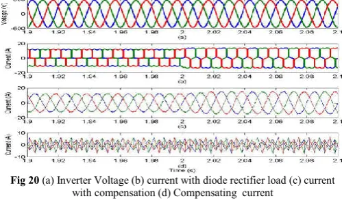
the available energy sources are depicted in Fig.19. The load demand is constant in this test case, so that the voltage magnitude is not affected. The real and reactive powers for the first test case without STATCOM and with STATCOM are shown in Fig. 20. It can be seen that the reactive power is compensated by the STATCOM,
Fig 18 Real and reactive powers (a), (b) without compensation and (c), (d) with
compensation
The total power generation by using the proposed energy management technique with the required load demand is illustrated in Fig.21. The proposed ANFIS technique effectively manages the load demand by properly calculating the reference values for the sources and storage devices. The current waveforms without compensation and with compensation for the diode load connected are sho
period 1.9 s to 2.1 s. Voltage variations in the micro grid due to inclusion and exclusion of loads are also taken care by the STATCOM. Here the load variations are small, so that the voltage profile is not getting affected much and small variations are compensated by the fast action of STATCOM. The real and reactive power of the system under two cases ie., without STATCOM and with STATCOM for the second test case are depicted. The proposed ANFIS based energy management scheme identifies the powe
available energy generation and finds the reference power values of the sources. Once, the renewable energy sources are failed to produce the required quantity of the power requirement means, the proposed control scheme manages the power requirement by utilizing the storage devices. Power quality issues of standalone HRES system such as harmonics due to nonlinear loads and voltage variations due to sudden switching of loads are also addressed by using the D STATCOM.
Fig.19 Total power generation with load power reference
the available energy sources are depicted in Fig.19. The load is constant in this test case, so that the voltage magnitude is not affected. The real and reactive powers for the first test case without STATCOM and with STATCOM are shown in Fig. 20. It can be seen that the reactive power is compensated by the STATCOM, which is shown in Fig. 20(d).
Real and reactive powers (a), (b) without compensation and (c), (d) with compensation
The total power generation by using the proposed energy management technique with the required load demand is Fig.21. The proposed ANFIS technique effectively manages the load demand by properly calculating the reference values for the sources and storage devices. The current waveforms without compensation and with compensation for the diode load connected are shown for the period 1.9 s to 2.1 s. Voltage variations in the micro grid due to inclusion and exclusion of loads are also taken care by the STATCOM. Here the load variations are small, so that the voltage profile is not getting affected much and small ions are compensated by the fast action of STATCOM. The real and reactive power of the system under two cases ie., without STATCOM and with STATCOM for the second test case are depicted. The proposed ANFIS based energy management scheme identifies the power requirement and the available energy generation and finds the reference power values of the sources. Once, the renewable energy sources are failed to produce the required quantity of the power requirement means, the proposed control scheme manages the wer requirement by utilizing the storage devices. Power quality issues of standalone HRES system such as harmonics due to nonlinear loads and voltage variations due to sudden switching of loads are also addressed by using the
Abhinav Shukla and Neelam Sahu., Anfis Based Management of Hybrid Renewable Energy Source In Smart Building
Fig 20 (a) Inverter Voltage (b) current with diode rectifier load (c) current
with compensation (d) Compensating current
Fig 21 Real and reactive powers (a), (b) without compensation and (c), (d) with
compensation
CONCLUSION
This paper proposed the ANFIS based energy management technique for the HRES connected with the ac load. The benefit of the suggested method includes the improved prediction ability and the lesser complexity in attaining the optimal values. The HRES have been developed with the help of the PV, WT, FC, UC and the battery. The proposed method identified the reference power for the energy sources based on the power values from the sources at previous instant and the load requirement at current instant. The control signals were developed as per the variations of the ac load. Then the proposed method was implemented and the simulated results are presented. The effectiveness of the proposed ANFIS based energy management method have been analysed with continuously varying environmental inputs and load conditions. From the analysis, it is evident that the proposed method effectively managed the power flow among HRES elements, and is proficient
References
1. M. Nehrir, C. Wang, K. Strunz, H. Aki, R. Ramakumar, J. Bing, Z. Miao and Z. Salameh, “A Review of Hybrid Renewable/Alternative Energy Systems for Electric Power Generation: Configurations, Control, and Applications”, IEEE Trans. Sustain. Energy, vol.2, no.4, pp.392-403, 2011.
2. T. Niknam, F. Golestaneh and A. Malekpour, “Probabilistic energy and operation management of a microgrid containing wind/photovoltaic/fuel cell generation and energy storage devices based on point estimate method and self-adaptive gravitational search algorithm”, Energy, vol.43, no.1, pp.427-437, 2012. 3. H. Dagdougui, R. Minciardi, A. Ouammi, M. Robba and
R. Sacile, “Modeling and optimization of a hybrid system for the energy supply of a Green building”, Energy Conversion and Management, vol.64, pp.351-363, 2012. 4. P. Bajpai and V. Dash, “Hybrid renewable energy
systems for power generation in stand-alone applications: A review”, Renewable and Sustainable Energy Reviews, vol.16, no.5, pp.2926-2939, 2012.
5. Z. Jun, L. Junfeng, W. Jie and H. Ngan, “A multi-agent solution to energy management in hybrid renewable energy generation system”, Renewable Energy, vol.36, no.5, pp.1352-1363, 2011.
6. T. Bogaraj, and J. Kanakaraj, “Development of MATLAB/SIMULINK models for PV and Wind Systems and Review on Control Strategies for Hybrid Power Systems”, International Review on Modelling and Simulations, vol.5, no.4, pp.1701-1709, 2012.
7. I. Satyanarayana, S. Ballala and V.B. Rama Krishnan, “Multilevel D-STATCOM for Linear and nonlinear loads to compensate reactive and active power during operation of distribution systems”, International Journal of Research in Engineering and Applied Science, vol.5, no.8, pp.98-105, 2015.
8. H. Joumaa, S. Ploix, S. Abras, S. Pesty, and G. D. Oliveira, “A MAS integrated into Home Automation System, for the resolution of power management Problems in Smart Homes”, Energy Procedia, vol. 6, pp.786-794, March 2011.
9. The Mathworks Inc., (2016) Fuzzy Logic Toolbox, [Online]. Available: http://www.mathworks.com/.
How to cite this article:
Abhinav Shukla and Neelam Sahu., 2018, Anfis Based Management of Hybrid Renewable Energy Source In Smart Building. Int J Recent Sci Res. 9(10), pp.29090-29097. DOI: http://dx.doi.org/10.24327/ijrsr.2018.0910.2790