RCOE T.E EXTC (SEMVI) B-3 Page 1 EXPERIMENT NO: 08
AIM: Study, Analysis of 16-QAM Modulation & Demodulation. APPARATUS: ST2136 16QAM kit,Patch Cords,CRO.
THEORY: Quadrature Amplitude Modulation (QAM) is a modulation scheme in which two sinusoidal carriers, one exactly 90 degrees out of phase with respect to the other, are used to transmit
data over a given physical channel. Because the orthogonal carriers occupy the same frequency band
and differ by a 90 degree phase shift, each can be modulated independently, transmitted over the
same frequency band, and separated by demodulation at the receiver. The 16 QAM Training system
is used for transmitting digital information over band-pass channels to conserve bandwidth at the
expense of increased power. It is used to obtain higher spectral efficiency, which potentially results
in higher throughput of packetized data. The Digital Data Generator is provided with Variable data
length (8, 16, 32, 64bits) and Variable Step Frequencies will flow through serially as an input to
QAM transmitter. The serial data is encoded by four bits and it is divided into two streams as Inphase
(I) & Quadrature (Q). I stream is called as odd sequence as it following odd values of the Data
pattern. Q stream can be called as even sequence as it following even values of the Data pattern. The
results from the Inphase (I) and Quadrature (Q) components are sent to Gray Encoder Block to
minimizing the Bit Error Rate (BER) for a given symbol error rate Then the Inphase (I) and
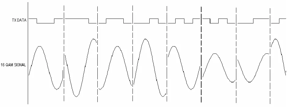
Quadrature (Q) components are multiplied with sine and cosine carriers to get I Modulation and Q Modulation and it’s get added to give QAM Signal.
The 16QAM Modulation Signal is the combination of I channel and Q channel. It has 16 symbol,
each symbol consist of 4 bits (i.e. I – 2 bits and Q- 2 bits) is explained in the constellation Diagram.
In the 16-QAM, the number of amplitude shift is fewer than the phase shifts. This is because, the
amplitude changes are susceptible to noise and require greater shift difference than do phase changes,
the number of phases shifts used by a QAM system is larger than the amplitude shifts. This meant
that even with noise problem associated with amplitude shifting is reduced. So QAM is lower
susceptibility to noise. QAM is used to obtain higher spectral efficiency, which potentially results in
higher throughput of packetized data.
The QAM Receiver (Demodulator) takes the modulated output from transmitter signal as input, and
it is multiplied with NCO Generated sine and cosine carriers to get I Demodulation and Q
RCOE T.E EXTC (SEMVI) B-3 Page 2
to obtain transmitted data. Hence, the results from the signal amplitude Detection have two bits of IG
& QG are send to Gray Decoder. The result from the Gray Decoder block consist of two bits of I
& Q and it will flow through the Four bits Decoding, which is used to Decode I & Q Bits into serial
data.
16- QAM Training System
Variable Clock Generator :
Clock Generator is the heart and is one of the important blocks in any digital sequential circuit
design. In ST2136 digitally synthesized clock of 50 % duty cycle with multiple of frequencies are
generated. The Clock Generator works with Variable Step Frequencies (150Hz, 300Hz, 600Hz, 1.2
KHz, 2.4 KHz, 4.8 KHz, 9.6 KHz and 19.2 KHz) can be controlled using DIP switches D2, D3, D4
RCOE T.E EXTC (SEMVI) B-3 Page 3 Variable Pattern Generator :
Pattern Generator or Data Generator is also a basic requirement for digital circuit analysis. Pattern or
Data Generator is used in Digital Communication as a data source. In ST2136 Data Generator is
provided with Variable data length (8, 16, 32, 64 Bit) Pattern of different length can be selected using
DIP switches (D5 – D6) and can be observed on the Test Point TP3. Below Table shows, the position
of DIP switches and respective Step Variable data length :
RCOE T.E EXTC (SEMVI) B-3 Page 4 Figure below shows the output of 16-QAM Modulation Signal with Variable Data :
The QAM Receiver (Demodulator) takes the modulated output from transmitter signal as input, and
it is multiplied with NCO Generated sine and cosine carriers to get I Demodulation and Q
Demodulation Signals. It is apparent that the demodulator performs the complement functions to
those in the modulator to get the transmitted data in the receiver.
RCOE T.E EXTC (SEMVI) B-3 Page 5 Block Diagram for I-Q Channel Symbol Demapper is shown below :
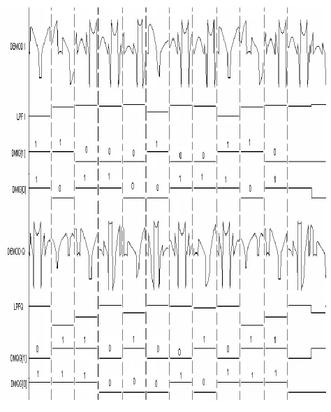
The Results from the I Demodulator and Q Demodulator signals are send to Low pass filter to
attenuate the high frequencies and pass them into low frequency. By means of Low pass filter, we can reduce the Noise and Intersymbol interference (ISI) in the received data. When the data’s gets
filtered in the Demodulator, it contains large data in it which has to be identified with respect to the
amplitude and detected for receiving the actual data. The range of amplitude is used to group data
range to obtain transmitted data. Hence, the results from the signal amplitude Detection has Gray
coded bits of IG & QG each consist of 2 bits.
Procedure :
· Observe the output of 16-QAM Modulation at test point TP18.
· Set the clock frequency, pattern length .
· Observe the output 4-Bit Encoding .
· Observe the output Binary to Gray Encoder.
· Observe the outputs of I Channel Demodulation at test point TP21, Q Channel Demodulation at test
point TP22, NCO Sine wave Generator at test point TP19 and NCO Cosine wave Generator at test
RCOE T.E EXTC (SEMVI) B-3 Page 6 Figure below shows the Demodulated Outputs I Channel and Q Channel for Low Pass Filter
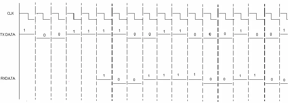
RCOE T.E EXTC (SEMVI) B-3 Page 7 Figure below shows the output of Transmitter and Receiver Data