Simulation software and virtual environments for acceleration of
agricultural robotics: Features highlights and performance comparison
Redmond Ramin Shamshiri
1,2,3*,
Ibrahim A. Hameed
2,
Lenka Pitonakova
3,
Cornelia Weltzien
4,
Siva K. Balasundram
1,
Ian J. Yule
5,
Tony E. Grift
6,
Girish Chowdhary
6(1. Department of Agriculture Technology, Faculty of Agriculture, Universiti Putra Malaysia, 43400, Serdang, Selangor, Malaysia; 2. Dept. of ICT and Natural Sciences, Faculty of Information Technology and Electrical Engineering, Norwegian University of Science and
Technology (NTNU), Larsgårdsveien 2, NO-6009 Ålesund, Norway; 3. Department of Computer Science, University of Bristol, Bristol, United Kingdom; 4. Leibniz Institute for Agricultural Engineering and Bioeconomy, Max-Eyth-Allee 100, 14469 Potsdam-Bornim, Germany; 5. New Zealand Centre for Precision Agriculture (NZCPA), School of Agriculture and Environment, Massey University,
Private Bag 11 222, Palmerston North 4442, New Zealand; 6. Department of Agricultural and Biological Engineering, University of Illinois at Urbana Champaign, 1304 West Pennsylvania Avenue Urbana, IL 61801, USA)
Abstract: Research efforts for development of agricultural robots that can effectively perform tedious field tasks have grown significantly in the past decade. Agricultural robots are complex systems that require interdisciplinary collaborations between different research groups for effective task delivery in unstructured crops and plants environments. With the exception of milking robots, the extensive research works that have been carried out in the past two decades for adaptation of robotics in agriculture have not yielded a commercial product to date. To accelerate this pace, simulation approach and evaluation methods in virtual environments can provide an affordable and reliable framework for experimenting with different sensing and acting mechanisms in order to verify the performance functionality of the robot in dynamic scenarios. This paper reviews several professional simulators and custom-built virtual environments that have been used for agricultural robotic applications. The key features and performance efficiency of three selected simulators were also compared. A simulation case study was demonstrated to highlight some of the powerful functionalities of the Virtual Robot Experimentation Platform. Details of the objects and scenes were presented as the proof-of-concept for using a completely simulated robotic platform and sensing systems in a virtual citrus orchard. It was shown that the simulated workspace can provide a configurable and modular prototype robotic system that is capable of adapting to several field conditions and tasks through easy testing and debugging of control algorithms with zero damage risk to the real robot and to the actual equipment. This review suggests that an open-source software platform for agricultural robotics will significantly accelerate effective collaborations between different research groups for sharing existing workspaces, algorithms, and reusing the materials.
Keywords: agricultural robotics, precision agriculture, virtual orchards, digital agriculture, simulation software, multi-robots DOI: 10.25165/j.ijabe.20181104.4032
Citation: Shamshiri R R, Hameed I A, Pitonakova L, Weltzien C, Balasundram S K, Yule I J, et al. Simulation software and virtual environments for acceleration of agricultural robotics: Features highlights and performance comparison. Int J Agric & Biol Eng, 2018; 11(4): 15–31.
1 Introduction
Advances in simulation platforms and virtual control
Received date: 2018-01-12 Accepted date: 2018-06-02
Biographies: Ibrahim A. Hameed, PhD, Associate Professor, research interests: machine learning, AI, optimization and robotics. Email: [email protected]; Lenka Pitonakova, PhD, research interests: swarm robotics, simulation of complex systems, neural networks, unsupervised learning. Email: [email protected];
Cornelia Weltzien, PhD, Professor, research interests: mechanical engineering, control systems and agricultural engineering. Email: [email protected];
Siva K. Balasundram, PhD, Associate Professor, research interests: precision agriculture, information system and technology, Email: [email protected]; Ian J. Yule, PhD, Professor, President of the International Society of Precision Agriculture, research interests: digital agriculture, system modeling and optimization, remote sensing, UAV. Email: [email protected]; Tony E. Grift, PhD, Associate Professor, research interests: agricultural robotics, advanced machinery for biosystems applications, automation and control. Email: [email protected]; Girish Chowdhary, PhD, Assistant Professor, research interests: Intelligent systems, field-robotics, multiple aerial vehicles. Email: [email protected].
*Corresponding Author:Redmond Ramin Shamshiri, PhD, research interests: control systems and dynamics, simulation and modeling. Department of Agriculture Technology, Faculty of Agriculture, Universiti Putra Malaysia, 43400, Serdang, Selangor, Malaysia. Tel: +60-3894-68472, Fax: +60- 386567099, Email: [email protected].
use of hand counters. Currently, there are no reports of a commercial robotic platform that can simultaneously map the yield parameters on-the-go prior to harvesting. The absence of an efficient robotic yield monitoring and environment mapping system is becoming a critical problem with increasing the uncertainties about the future availability of the labor force that is willing to accept tedious jobs in the harsh greenhouse condition. Moreover, manual data sampling implies high costs and low accuracy and is significantly influenced by the interpretation of the person involved. The functionality of robots when combined with data processing, analyzing models, and artificial intelligence will assist farmers to manage their fields and plants more efficiently. Improvement of robotics for agricultural application however requires experimenting with different sensors and algorithms, as well as evaluating different strategies for finding the optimum solution to perform a field task. Experimenting with the physical robots and sensors in an actual field, orchard, or greenhouse is not always possible due to the time constraints, unavailability of equipment (i.e., sensors, cameras, and the robot itself), and the operation costs involve. In the other hand, some hardware setups may result in actuator saturation, or create an unsafe situation for the operators and/or tree and plants system. To accelerate this pace, simulation methods can provide an affordable framework for experimenting with different sensing and acting mechanisms in order to verify the performance functionality of the robot in different scenarios. Simulation offers a reliable approach to bridge the gap between innovative ideas and the laboratory trials, and therefore can accelerate the design of a robust agricultural robotic platform for efficient, cost-effective and collision-free navigation task in field and orchard.
The organization of this paper is as follow: description of the Robot Operating System (ROS), selected professional simulators and custom-built virtual environments for agricultural robotics are covered in section 2. In this section, we have also included a brief introduction about sample agricultural projects for each simulator when available. Section 3 is dedicated to the evaluation and performance comparison between Virtual Robot Experimentation Platform (V-REP), Gazebo, and ARGoS. Section 4 extends our discussion on the functionalities and features of V-REP through a case study on simulation of robotic scouting in a virtual citrus orchard. Results of this case study were used as a proof-of-concept framework for experimenting with different sensing and acting scenarios and verified powerful functionalities of the simulator.
2 Simulation environments
A key step toward acceleration of robotics is the choice of simulation software, middleware operating systems, and virtual environment platforms. Simulation in general refers to the practice of developing and programming virtual models and objects that together are capable of emulating specific tasks, ideas, or a proposal process in the real-world. Computer simulation and control of agricultural robotics require a multidisciplinary knowledge about different software and hardware to create an integrated virtual experiment environment within which the behavior of various objects (i.e., robot models and sensors) and control tasks (i.e., path planning and visual servoing) can be evaluated[1]. Unlike the industrial applications, an agricultural robot
interacts with highly variable dynamic environments which necessitate incorporation of horticulture and agronomy science to successfully accomplish a task. For example, a criterion for
utilization of the sensors in agricultural robots lies in the requirements of fast response with high temporal and spatial resolution which is difficult to measure under unfavorable field conditions. Hence, the objective of simulation and other analysis methods is to combine the real-world and virtual data to fuse the different information layers and derive new knowledge. In the case of field robots for precision agriculture application, real-time data processing on-the-go is sometimes necessary and should be embedded in the sensors so that the results are directly available to the robot for carrying out precise management actions. Virtual environments and middleware frameworks such as the Robot Operating System (ROS)[2] offer great opportunities for processing
these sensor readings in the third party software such as the Open Source Computer Vision Library (OpenCV) and MATLAB. It is also possible that the outputs and results from a simulation study be installed and implemented on the actual robots directly, without further calibration. Other general advantageous of simulation for accelerating agricultural robotics include (i) reduced cost and shortened time for testing the hardware and software before the actual implementation, (ii) easier diagnosing and debugging of the programming codes, (iii) compatibility with different programming language and external control software, (iv) breaking a complex robotic projects into separated scenes, (v) eluding actuator saturation and mechanism breakdowns, and more importantly (iv) avoiding risks and hazards to the human and environment. The main drawbacks of the simulation is that the real world may present more complicated situations such as unexpected disturbances to the actuators, or unpredicted noise to the sensors feedback as a result of natural field conditions. While professional versions of many simulation platforms offer advanced features to create more realistic scenes, it is nearly impossible to completely cover every single detail of the actual-world scenarios into a simulation project. This is however not considered a burden since simulation is meant to be an initiative for evaluating the sketch ideas and the proof-of-concepts designs. An example is shown in Figure 1 where the concept of mass harvesting with arrays of single and dual axis robots have been evaluated in two different simulation environments, the Actin (Cambridge, MA, USA) and V-REP, respectively for citrus and sweet pepper fruits. In fact, many experts agree that the first step in designing and developing robots should be the simulation because it does not depend on the actual physical components, and therefore modification of different parts and programs can be done easier and faster on the virtual models. In addition, offline programming using simulation eliminates the downtime for an operational process such as a fruit packing line.
There is a long list of academic and professional simulation platforms that can be adapted and used for agricultural robots. Examples include Webots[3], Gazebo[4], CARMEN RNT[5],
Coupled Layer Architecture for Robotic Autonomy (CLARAty) [6], [7], Microsoft Robotics Developer Studio (MRDS)[8], Orca[9], Open
Robot Control Software (Orocos)[10], Player [11], the Autonomous
Mobile Outdoor Robot (AMOR)[12], and Mobotware[13]. In
addition, several efforts have been made toward creating simulation platforms and frameworks that are based on the professional simulators and are customized for agricultural robotics or farm machinery. Examples include FroboMind[14] (based on Orocos
and ROS), the Agricultural Architecture (Agriture)[15] (based on
Gazebo, Player, and Java Agent), Agroamara[16], and the Software
Architecture for Agricultural Robots (SAFAR)[17,18] (based on
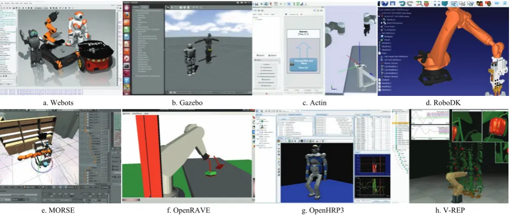
wide range of models, functionalities, external controllers, and a user-friendly graphical interface. Most of the mentioned simulators are compatible with other programming languages or computational software (i.e., C/C++, Perl, Python, Java, LabVIEW, URBI or MATLAB). For the sake of this chapter, we introduce some of the most common simulation software tools that are used by the robotic community and can be adopted for agricultural robotics. Figure 2 shows screenshots of workspace environment for (a) Webots[3], (b) Gazebo[4], (c) Actin[19], (d) RoboDK[20], (e)
the Modular OpenRobots Simulation Engine (MORSE)[21], (f) the
Open Robotics Automation Virtual Environment (OpenRAVE)[22],
(g) the Open Architecture Human-centered Robotics Platform (OpenHRP3)[23], and (h) the Virtual Robot Experimentation
Platform (V-REP)[24]. These simulators offer competing
functionality and advanced graphical user interface, built-in models, controllers, and dynamic engines. A comparison between the general specifications of these platforms is summarized in Table 1. For example, one of the significant advantageous of V-REP over Gazebo is that CAD models can be created directly in the V-REP environment. V-REP also has multiple tools, plugins, and functionalities that allow connections to external software and interfacing with real-world environment. In the following
a. Actin simulation for robotic harvesting with multiple manipulators, Source: Energid Technologies
b. V-REP simulation for robotic harvesting with multiple manipulators[1] Figure 1 Screenshots of the simulation scenes in Actin (Top) and
V-REP (bottom) for evaluating the concept of robotic mass harvesting with arrays of single and dual axis robots
a. Webots b. Gazebo c. Actin d. RoboDK
e. MORSE f. OpenRAVE g. OpenHRP3 h. V-REP
Figure 2 Screenshots of workspace environment for some of the most commonly used simulation software Table 1 Comparison between general specifications of the selected simulation software for agricultural robotics Simulation
software Developer
Physics engine
Supported operating systems
Prog language
CAD files support
API support
ROS support Webots[3] Cyberbotics Ltd Proprietary based
on ODE Linux, Mac OS, Windows C++ WBT, VRML, X3D
C, C++, Python,
Java, Matlab, ROS Yes Gazebo[4] Open Source Robotics
Foundation
ODE, Bullet,
Simbody, DART Linux C++
SDF/URDF, OBJ, STL,
Collada C++ Yes
Actin[19] Energid Technologies Proprietary Windows, Mac OS, Linux, VxWorks, and RTOS-32.
(RTX and QNX Planned)
C++
SLDPRT, SLDASM, STEP, OBJ, STL, 3DS, Collada, VRML, URDF, XML, ECD, ECP, ECW, ECX, ECZ,
Not known Yes
RoboDK[20] RoboDK None Linux, macOS, Windows,
Android Python STEP, IGES, STL, WRML
C/C++, Python,
Matlab No
Morse[21] Academic community Bullet Linux, BSD*, Mac OS Python Unknown Python Yes
OpenRAVE[22] OpenRAVE
Community ODE, Bullet Linux, Mac OS, Windows
C++, Python
XML, VRML, OBJ, Collada
C/C++, Python,
Matlab Yes
OpenHRP3[23] AIST ODE, Internal Linux, Windows C++ VRML C/C++, Python, Java No
ARGoS[25] Swarmanoid project Multiple-physics
engines Linux and Mac OSX C++ Does not support C++ Yes
V-REP[24] Coppelia Robotics ODE, Bullet,
Vortex, Newton Linux, Mac OS, Windows LUA
OBJ, STL, DXF, 3DS, Collada,URDF
subsections, we provide a brief description of ROS and the selected simulators shown in Figure 2. We also introduce sample projects when available. Because building of complex simulation scenarios for agricultural robots is only possible through a distributed control framework, we have extended our discussion about V-REP as a case study in section 4.
2.1 Robot Operating system (ROS)
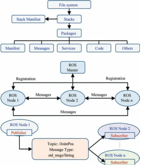
ROS[2] is an open-source flexible middleware that provides
services, libraries, and tools for developing different robotic applications. It is in fact a collection of software framework that was originally developed in 2007 by the Stanford Artificial Intelligence Laboratory, and with the support of the Stanford AI Robot project. ROS is installed on Linux operating system family (i.e., Ubuntu) and provides a solution to specific set of problems encountered in the developing large-scale service robots, with philosophical goals summarized as: (i) peer-to-peer, (ii) tools-based, (iii) multi-lingual, (iv) thin, and (v) free and open-source[2]. From
2008 until 2013, development was performed primarily at Willow Garage, a robotics research institute/incubator. During that time, researchers at more than twenty institutions collaborated with Willow Garage engineers in a federated development model. Since 2010, ROS has released several versions, including Box Turtle (March, 2010), C Turtle (August, 2010), Diamondback (March, 2011), Electric Emys (August, 2011), Fuerte Turtle (April, 2012), Groovy Galapagos (December, 2012), Hydro (September, 2013), Indigo (July, 2014), Jade Turtle (May, 2015), Kinetic Kame (May, 2016), Lunar Loggerhead (May, 2017), and Melodic Morenia (May, 2018). The open-source ROS makes it possible to develop code and applications that can be shared and used in other robotic systems with minimum effort. Solutions to various robotic problems are also available on the ROS wiki community (http://wiki.ros.org). This middleware has gained such a vast popularity that many professional robots companies have released ROS drivers for their products. It also offers standard operating system features such as hardware abstraction, low-level device control, implementation of commonly used functionalities, message passing between processes, and package management. The official programming languages supported by ROS are python and C++. The implementation of the ROS is created by the file building system called the catkin. It can run on one computer or connect multiple computers to one computer called ROS master. Schematic diagram of ROS file architecture and principle of nodes communication system are shown in Figure 3. Fundamental concepts of the ROS are: Nodes, Messages, Topics, and Services. This structure allows creation of a modular network of nodes that are dedicated to subset computations with an organized communication between them. In addition, robotic libraries such as frame transformation or motion simulation can be shared with all nodes to simplify the computation process. ROS Packages are files and folders that are built to create minimal collections of code for easy reuse. It works based on a “publish-and-subscribe” architecture where processes (called Nodes) publish and/or subscribe to specific Topics on which information is exchanged in the form of Messages. For example, ROS can be used to provide a bi-directional communication (information exchange) between a simulated robot and different real-world cameras that are each implemented in ROS as a node. A Node is an executable file that uses ROS to communicate with other Nodes. A Message is a ROS data type defined in a text file as a structure of variables of different data types that is used when subscribing or publishing to a
Topic. Nodes can publish messages to a Topic as well as subscribe to a Topic to receive messages. In fact, a Topic acts as a gateway for publishing and subscribing specific messages in the ROS environment. For example, information about a joint position can be subscribed by the corresponding ROS node from the topic called JointPos where the information is published by ROS node on the robot (Figure 3). Service helps Nodes find each other. ROS nodes use a ROS client library to communicate with other nodes. Nodes can also provide or use a Service. With this architecture, each node in ROS can respond to input and activate other nodes, allowing participation of a sequence of nodes to complete complicated robot mission tasks. Installation details and basic configuration of ROS environment, as well as installation and configuration of packages such as V-REP/ROS bridge, and the details of several mobile robot and manipulator package can be found in [26]. A good article sharing some experiences with ROS for development of agricultural robots is available in [27].
Figure 3 Diagram showing ROS file architecture and principle of nodes communicating system for a random topic 2.2 Webots, Actin, and Gazebo
Webots[3] robot simulator was developed at the Swiss Federal
Institute of Technology (EPFL) in 1996 and can be downloaded from Cyberbotics company website (Lausanne, Switzerland). This simulation platform supports C/C++, Java, Python, URBI, and MATLAB language, and can be interfaced with third-party applications through TCP/IP. It is widely used for academic and educational purposes due to the friendly and simple graphical user interface and the long list of models and components.
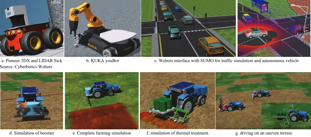
Benchmark website which holds online robot programming challenges to millions of users worldwide has recently provided free access to various robotics standards and components based on the Webots simulations via the website interface of Webots. Robot scripts are run in the cloud, and 3D views are displayed in the internet browsers, allowing users to program the robots in Python. Moreover, Webots has open-source APIs, which makes it easier to use the libraries of choice with a preferred programming language for implementation. For example, Webots can be used with OpenCV functions for efficient real-time image processing. Figure 4d-g show sample screenshots from simulation phase of a project funded by the European Union called Robot Fleets for Highly Effective Agriculture and Forestry Management (RHEA). This project used Webots for the design, development, and testing of a new generation of automatic and robotic systems for weed management and control. It covered a wide variety of products including row crops and forestry woody perennials in which various simulations were involved (i.e., simulation of autonomous robot spraying herbicides, simulation of sprayer implement, and simulation of a treatment mission in a tree canopy with a special tractor implement). The screenshots provided in Figure 4d-g are from the RHEA video demos for (d) adapted boomer tractor, (e) simulation of a complete mission in a crops field with mobile units and processing techniques, (f) simulation of a PWC implement for thermal and mechanical treatment of wheat crops developed by the University of Pisa, and (g) simulation of three tractors driving on an uneven terrain. Perhaps Webots can be considered as one of the most widely used simulators for research and development in autonomous tractors and agricultural mobile robots.
Actin is a robotics software toolkit simulator, developed in 2005 by Energid Technologies (Cambridge, MA, USA), mainly for robot controls with related functions and features such as path planning, motion planning, collision avoidance, and joint controls. It supports various communication protocols including Modbus, EtherCAT, CANopen, Serial, Data Distribution Service, UDP, and TCP in order to create a connection between the operator and the physical hardware. Using acting can significantly reduce the time and cost of projects that involves robotics, and also optimizes
existing processes and workflows. Actin is employed in different fields of industries and transportation with very limited examples in agricultural robotics. The robotic citrus picking system in Figure 1 uses Energid's frog tongue design and high-speed vision sensors and is simulated in Actin. One of the key advantages of this simulator is that it is able to handle bifurcated problems and control kinematically redundant robotic systems. This unique ability allows coordinated lifts using multiple robots. It also supports constraining closed-kinematic chains for bi-handed manipulation. Programs in Actin are task-based and part relative, meaning that when the robot components move during manipulation, the motion is adapted in real-time to complete the task.
Gazebo is one of the most popular multi-robot simulators which support a wide range of sensors and objects. It was used as the standard simulator for the RoboCup2016 competition. Gazebo was initially a part of ROS environment in the previous versions, but today it can be downloaded for free and be used as standalone software. It is an open-source simulator (i.e., plug-in with model components can be developed and shared) with multiple physics engines that run on Linux (protected versions for Windows is also available) and is compatible with ROS, Player, and several other robotic platforms from the Willow Garage. Complex robotic systems that involve interaction, object lifting and grasping, and other tasks that require simultaneous localization and mapping can be simulated with the Gazebo powerful physics engines using a much higher realistic scenarios and degree of reliability. According to the IEEE Spectrum magazine[28], Gazebo is
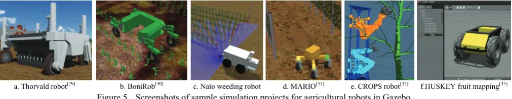
recognized by many experts as the best robotic simulator because of (i) the ability for accurate simulation, (ii) extreme flexibility, (iii) having four different physics engines, (iv) great integration with ROS, and (v) a large and active community of contributors. Figure 5 shows screenshots of sample agricultural robotic simulations in Gazebo for (a) Thorvald robot[29], (b) BoniRob[30], (c)
a weeding robot developed by Naïo Technologies (Escalquens, France), (d) the MARIO robot operating in a virtual typical vineyard[31], (e) the CROPS robot manipulator performing task and
motion planning for apple harvesting[32], and (f) the HUSKEY
mobile robot for fruit mapping[33].
a. Pioneer 3DX and LIDAR Sick b. KUKA youBot c. Webots interface with SUMO for traffic simulation and autonomous vehicle Source: Cyberbotics Webots
d. Simulation of boomer e. Complete farming simulation f. simulation of thermal treatment g. driving on an uneven terrain Source: RHEA projects, http://www.rhea-project.eu/.
a. Thorvald robot[29] b. BoniRob[30] c. Naïo weeding robot d. MARIO[31] e. CROPS robot[32] f.HUSKEY fruit mapping[33]
Figure 5 Screenshots of sample simulation projects for agricultural robots in Gazebo 2.3 RoboDK, MORSE, OpenRave,OpenHRP3, and ARGoS
RoboDK[20] is a highly versatile offline programming and
simulation software that is mainly used for industrial robots. It is available for free download or purchase at robodk.com website. RoboDK has a diverse CAD model library that consists of over 200 professional industrial robots and tools from leading manufacturers including ABB, KUKA, Yaskawa, and Adept. Some of these robots are used in agriculture industry for packaging and materials handling. The 3D simulation environment of RoboDK offers playback feature within which operator can visualize every aspect of the robot behavior. Alerts are generated when singularities or collisions are detected for a robot.
MORSE[21] was first released in March, 2013. It is a
command-line simulator developed by OpenRobots community (www.openrobots.org). MORSE does not come with a graphical user interface. Instead, realistic 3D simulation scenes are created using Python scripts, and for this reason, it is most suitable for experienced computer scientists. MORSE can be downloaded for free at https://www.openrobots.org/wiki/morse. There are two different strategies in MORSE for handling the simulation time, (1) the best effort that keeps a real-time pace (simulation frames may be eliminated to achieve this), or (2) fixed steps, which guarantees that simulation is accurate. Because MORSE is a pure Python application, it enables easy and fast modification of the final source codes. It is a modular simulator in which new actuators or sensors can be added easily. It should be noted that advanced robotic algorithms such as path planning have not been embedded in MORSE. It is basically a not-for-profit academic project developed to operate on Linux (also known to work with MacOSX and Microsoft Windows) that do not offer professional supports, however models of several standard robot bases such as Pioneer3DX, generic 4 wheel vehicle, and PR2, as well as standard set of sensors (i.e., RGB cameras, GPS, and laser scanners) and actuators (i.e., joint controllers) are available in MORSE.
OpenRave[22] began as a project in 2006 at the Carnegie
Mellon University Robotics Institute and can be downloaded from openrave.org. The main focus of OpenRave is on simulation and analysis for testing, developing, and deploying kinematic and geometric information that are related to algorithms for motion planning application. Most of the algorithms and the implemented calculations are for robotic manipulators and are used for exploration of task configuration space. OpenRave targets industrial application, it can be easily integrated into existing robotics systems by providing command line tools and interfaces. One of the most influential technologies in OpenRAVE is the Robot Kinematics Compiler, known as IKFast, which can run as fast as 5 microseconds on recent computers, resulting in extremely stable solutions. The IKFast can solve the kinematics equations of any complex kinematics chain analytically,
and create language-specific files (i.e., in C++) for future use. Moreover, the COLLADA 1.5 file formats are supported by OpenRAVE for specific robots, manipulators, sensors, and planning-specific parameters.
OpenHRP3[23] is an open-source distributed object system
simulator. It is an integrated platform that provides users with an integrated environment for inspecting original robot models and implementing control codes through various components and calculation libraries for a dynamic simulation. OpenHRP3 is composed of a client program that manages the servers, and a group of server programs that offers various functions. It improves the portability and maintainability in complex and large-scale simulation system developments. According to the publisher website, “the dynamics calculation engine of OpenHRP3 has two editions, the development of the Tokyo University, and the development of AIST. The first edition applies an original algorithm for a forward dynamics calculation, while the second applies Featherstone's algorithm and performs a forward dynamics calculation in computational complexity to be proportional to the number of the joints”.
As mentioned in Section 2.4, a swarm of robots is a promising approach for providing efficient solutions to autonomous scouting and field data collection in agriculture. The main idea is to control large numbers of (i.e., 500 or 1000) small-scale robot agents that are affordable but have limited sensing and processing capabilities in a way that they accomplish a common field task. Some of the aspects to be considered for these type of robotic applications are the environment dynamics (i.e., wind and rough terrain), robot type (i.e., mechanism, sensors, and actuators), and the communication system (i.e., wifi, vision, and stigmergy). These factors, as well as the limitations in the modeling and computation, create complexity and inaccuracy for simulation of a swarm of robots. Most of the existing simulators obtain scalability (by imposing limitations on their extensibility and on the accuracy of the robot models) and utilize a specific physics library. As a result, their accuracy is strongly linked to the accuracy of their employed physics library. Although they emphasize on the flexibility and give the best results in single-robot or small-scale multi-robot applications, their performance degrades fast with large numbers of robots. In other words, they do not provide the necessary features to support large-scale heterogeneous robot swarms. As a response to this limitation, an open-source multi-physics engine robot simulator named ARGoS[25] has been developed for efficient real-time
modular approach that allows adding custom features and allocating computational resources depending on the simulation need. Results of evaluating ARGoS have shown that it can simulate 10,000 wheeled robots 40% faster real-time[25]. It
should be noted that all of the components such as robot models, sensors, actuators, physics engines, and visualizations in ARGoS are implemented as plugins.
2.4 Virtual robot experimentation platform (V-REP) V-REP[24] is a true cross-platform that can be run in Windows
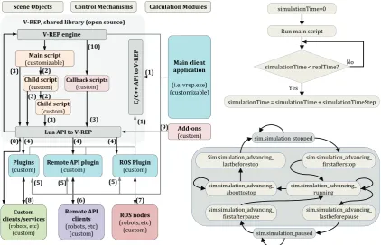
or Linux and is referred to as a Swiss knife in robotic simulation community due to the multiple functionalities. It was first released in March 2010, and the latest version (V3.5.0) is available since February 6th, 2018. This simulator offers a distributed
control framework solution with advanced functionalities for testing and debugging complex robotic systems. In other words, each object or model in a V-REP scene can be individually controlled through several ways such as child script, writing plugins, ROS nodes, external client applications that relies on the remote API, or writing an external application that communicates with V-REP plugin or script via pipes, sockets, or serial port. By default, the V-REP distribution for Linux should be automatically ROS enabled based on ROS Indigo and Catkin. V-REP possesses various relatively independent functions, features, or more elaborate APIs such as MATLAB, that can be enabled or disabled as desired. The schematic architecture of the V-REP framework and corresponding internal states are shown in Figure 6. It can be seen that simulation time in V-REP is advanced at constant time steps, and depending on the complexity of the scene and performance of the computer, the real-time of simulation is supported by keeping the simulation time synchronized with the real -time (which might not always be possible). The distributed control architecture of V-REP makes it versatile and suitable for
simultaneous use of different mobile robots, manipulators, and related objects in a simulation. Controllers can be written in C/C++, Python, Java, Lua, Matlab, Octave, or Urbi. The three main elements of V-REP simulator are scene object (i.e., joints, shape, sensors, path, etc), calculation modules (i.e., inverse kinematics, collision detection, etc), and control mechanism (i.e., scripts, plugin, sockets, etc as shown in Figure 6. Control entities are distributed in V-REP which accelerates the simulation by allocating the CPU load over several cores or several machines. Compared to Gazebo, V-REP is more stable with easier setup and running. For example, the vision sensors are reasonably well simulated in V-REP, and if the scene is not too complex, the run times of the simulations are generally good as well. V-REP is also capable of importing the URDF files that are created for other simulators like Gazebo. External applications can be connected to V-REP using Remote API which is available for MATLAB, C++, Python, and Java programming languages. The remote API functionality relies on the remote API plugin (on the server side), and the remote API code on the client side. Both programs/projects are open-source (i.e. can be easily extended or translated for support of other languages) and can be found in the 'programming' directory of V-REP's installation. In addition, V-REP inverse kinematics supports four different dynamic engines: The Bullet, ODE, Newton, and the Vortex Dynamics Engine. Models in V-REP are flexible, portable and scalable, meaning that it is possible to modify them, copy from one project scene to another, or resize them in place. If the project requires building a custom robot model which is not available in the simulator (i.e., the manipulators demonstrated in[1,34,35]), the setups for links, joints
and calculation modules such as inverse kinematics necessitates some practice, however, that is the case in any robot simulation software.
Sim.simulation_advancing_
lastbeforestop sim.simulation_advancing_ firstafterstop
sim.simulation_advancing_ abouttostop sim.simulation_advancing_ lastbeforepause sim.simulation_advancing_ firstafterpause sim.simulation_advancing_ running sim.simulation_stopped sim.simulation_paused simulationTime=0
Run main script
simulationTime < realTime?
simulationTime = simulationTime + simulationTimeStep No
Yes SceneObjects ControlMechanisms CalculationModules
V‐REPengine
C/ C+ + API to V ‐ REP
LuaAPItoV‐REP
Plugins
(custom) Remote(custom) APIplugin ROS(custom) Plugin
Mainclient application (i.e. vrep.exe) (customizable) Mainscript (customizable) Childscript (custom) Childscript (custom) Callbackscripts (custom) Custom clients/services (robots, etc) (custom) RemoteAPI clients (robots, etc) (custom) ROSnodes (robots, etc) (custom) V‐REP,sharedlibrary(opensource)
Add‐ons (custom) (3)
(3)
(3) (3)
(10)
(8) (6) (7)
(5) (5)
(5)
(1) (9)
(8) (4) (4) (4)
(2)
(2)
(1)
Figure 6 Schematic view of the V-REP framework architecture, simulation state diagram, and the real-time simulation loop Simulation scene in V-REP contains several elemental objects
that are assembled in a tree-like hierarchy and operate in conjunction with each other to achieve an objective. In general, a
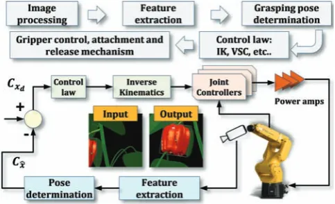
and drop operation between the explored and the application window, and are saved as “.ttt” files. Moreover, V-REP has several calculation modules that can directly operate on one or several scene objects. Figure 7a shows screenshots of a V-REP scene for simulation of sweet pepper robotic harvesting using Fanuc LRMate 200iD 6-DoF manipulator and artificial plants and fruits models[1]. The visual servo control scheme associated with
this project is shown in Figure 8. A similar project with the same manipulator was carried out in ROS MoveIt (visualized in RViz) for the SWEEPER project (sweeper-robot.eu) as shown in Figure 7b. The differences between the visual details and modeling features of the two scenes as well as the control functionalities of the robots are noticeable.
a. V-REP scene [1] visualized in Rviz using vision sensor publisher (robot control and image processing in MATLAB) b. ROS MoveIt and RViz
Source: AdaptiveAgroTech.com Source: sweeper-robot.eu
Figure 7 Comparison between visual features of the ROS MoveIt and the V-REP environment for a similar robot manipulator (Fanuc LRMate 200iD) and application
Figure 8 Visual servo control scheme with the eye in hand configuration based on image moment method used with the Fanuc
LRMate 200iD manipulator for harvesting of sweet pepper[1]
2.5 Other simulators and virtual environments
Other than the highlighted professional simulators, customized virtual environment solutions can be developed from scratch using combinations of different software, environment solutions can be developed from scratch using combinations of different software, however this will be extremely time-consuming. Some projects have employed combined features of programming languages (i.e., visual basic), computational software (i.e., MATLAB), CAD models, and virtual platforms to create farming simulator environments. For instance[36], used the programming language
C++ and Borland Delphi with ARToolKit and GLSCene for simulating robotic harvesting of citrus with a redundant manipulator (Figure 9a, the image is courtesy of Hanaian and the University of Florida). Another example is the simulation of conceptual robotic harvesting from Vision Robotics (shown in Figure 9b) which uses multiple manipulators for mass harvesting. Figure 9c shows a simulation of path planning for a tractor in Jaybridge simulation environment (image is courtesy of Jaybridge Robotics). Simulation of a manipulator that was controlled via MATLAB and was used in the design and simulation process of two robotic systems for automatic artichoke harvesting[37] is
shown in Figure 9d (simulation environment has not been mentioned in the original article). Figure 9e shows a harvesting
operation simulator software designed by AnyLogic for modeling the relationship between a grain combine, a grain cart, and a truck. This software also demonstrates the logistical dynamics that are associated with harvesting crops and provides users with capabilities and feature to visualize the complexities involved for optimizing the interaction of equipment during harvest. A good example of customized simulation platform is SAFAR, the Software Architecture for Agricultural Robots. This is a joint project of UniBots (a university spin-off company based in the UK) and MobotSoft (www.mobotsoft.com) for an academic initiative for easy-to-use by non-programmers to develop a set of designs, tools, and resources to simulate agricultural robots and promote precision agriculture and smart farming[17,18]. The
simulation scenes are created in Microsoft Robotics Developer Studio (MRDS)[8]. Sample screenshot from a tractor simulation
in SAFAR is shown in Figure 9f. A new version of this platform is SAFAR2 (can be downloaded from Mobosoft website) that includes a desktop application interfaced with Google Earth and MRDS for easier use.
In the new version of SAFAR, a random image taken from a field in any part of the world can be inserted into the software, then a route plan can be created for a selected robot in order to simulate a specific farming operation in MRDS without writing a single piece of code. It should be noted that SAFAR supports Python scripting engine and is closed source. Another example of using MRDS for agricultural robots is the simulation of Omnirota shown in Figure 9g (screenshot was captured from CornIsKing Youtube channel).
cultivation, spread fertilizer, simulate plow jobs and seeding, use drill machine attached to the tractors, move crops and animals in and out of the farms, work with sprayers and pesticide, perform harvest operation, and even sell the products. This virtual
environment gives users the benefits of learning difficult tasks such as parking of tractors which requires skill to be carried out in the real situation.
a. Citrus harvesting robot[36] b. Multiple robots for mass harvesting c. path planning of for a tractor, Jaybridge Robotics simulation environment
Hanaian, the University of Florida Source: Vision Robotics
d. Harvesting of artichoke[38] e. Harvesting in AnyLogic modeling software f. SAFAR tractor in MRDS g. Omnirota in MRDS
Source: SAFAR project Source: CornIsKing Youtube channel Figure 9 Examples of simulation projects in custom-built or non-professional simulator software
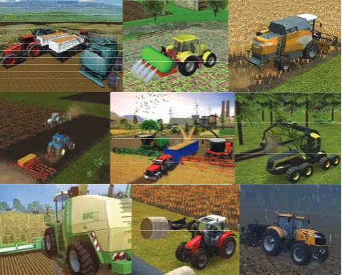
Figure 10 Screenshots of Farm Sim game for virtual experience with agricultural machinery (Courtesy of farming-simulator.com)
3 Performance comparison: V-REP, Gazebo,
ARGoS
V-REP, Gazebo, and ARGos share several similarities such as programming in C++ and ROS support, they also demonstrate clear differences when analyzed for the trade-off between scene complexity and computational performance. For instance, V-REP offers the widest range of features including, most notably, scene editor and visualization, importing different mesh file formats, in-scene mesh manipulation, built-in video recording, and several API supports (i.e., C/C++, Python, Java, Urbi, Matlab/Octave) for remotely connecting to a simulation. The model library in V-REP is relatively large, flexible, and well documented, and the graphical interface is easy to learn. Most importantly, compared to Gazebo and ARGoS, installation of V-REP is more straightforward, allowing users to immediately begin a project with the minimum
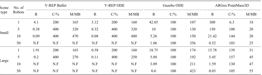
In order to analyze and compare the characteristics and performance of V-REP, Gazebo, and ARGoS, we conducted several tests in the 64-bit Ubuntu Linux 16.04 environment running on a computer with 4x Intel Core i7 2.2 Gz processor, 8GB RAM and Intel HD Graphics 6000 graphics card. There were two types of benchmark test performed with each simulator, the GUI, and the Headless benchmark. The GUI benchmark involved running a simulation of robots that moved in a straight line and avoided obstacles in real-time. The simulators were run along with their user interfaces. Each simulation took one minute. Detailed results of this test are available in [39]. The headless benchmark involved running the same simulation as in the GUI benchmark that lasted five minutes. The simulators were run from the command line without their user interfaces. We also used two types of simulation environment, “Small Scene” (where robots were put on a large 2D plane), and “Large Scene” (where an industrial building model with approximately 416000 vertices was imported into the simulator). A detailed description of the tests setup and methodology is available in [39]. Three performance metrics were used to evaluate the simulators: (i) real-time factor (denoted by R, defined as the simulated time divided by the real-time), (ii) the amount of CPU usage (denoted by C in percentage), and (iii) the amount of memory usage (denoted by M in Megabyte). A value of R>1 indicates that a simulation could run faster than the real-time and vice versa. Also, when C>100%, a simulator could utilize multiple processors cores. Two values for C and M were noted for Gazebo GUI experiments, corresponding to the usage of “gzclient” (visualisation) and “gzserver” (simulation), respectively.
Results of these tests are given in Table 2, indicating that ARGoS achieved the highest simulation speed in the GUI experiments with up to 50 robots in the Small scene and with up to 5 robots in the Large scene, while utilizing the smallest amount of resources. Gazebo outperformed ARGoS in other experiments, especially when the Large scene was used in the Headless. However, Gazebo usually required the largest amount of memory when it was running in the GUI mode, and a median amount in the Headless mode. V-REP combined with ODE usually achieved the lowest simulation speed. Using Bullet 2.78 often significantly
increased the performance of V-REP. Running Gazebo and ARGoS in the Headless mode (Table 2) increased R in environments where maximum CPU power was utilized by the GUI mode. On the other hand, R was often smaller in the Headless mode of V-REP, compared to its GUI mode. V-REP demonstrated the most optimal CPU utilization. It automatically spawned new threads when it was necessary and it could thus fully utilize all available CPU cores. Gazebo only utilized a single CPU core per process. In the GUI mode, Gazebo ran two processes, “gzclient” and “gzserver”, that could each utilize a maximum of 100% of CPU power. In the Headless mode, only a single core was utilized, as only the “gzserver” process was running. The multi-threaded core utilization by ARGoS worked in general but problems were experienced in larger experiments. The CPU usage was notably smaller when more robots were added to the environment. Furthermore, unlike V-REP, ARGoS requires the user to specify the desired number of threads, rather than automatically spawning new threads when it is necessary. It should be noted that the 3D models used in ARGoS and Gazebo were fairly simple compared to those used in V-REP, even though an effort was made to simplify the V-REP robot model. Moreover, the ARGoS physics engine was much simpler than those used by V-REP and Gazebo. It is therefore expected that using third-party libraries to cope with various aspects of the simulation that are currently not covered in ARGoS, such as calculating more complex physics dynamics or working with imported 3D meshes, would decrease the simulator's performance. Similarly, it is expected that more complex 3D models would decrease the performance of Gazebo compared to V-REP. In order to confirm that the mesh complexity played a major role in V-REP, several experiments were ran[39] using robots and scenes consisting of very simple 3D
meshes and models in the absence of sensing and controller capabilities. Results showed that an increase between 66% and 600% in R could be achieved, using only about 15% to one eighth of the computer's resources. These results[39] suggest that it is possible to significantly increase the performance of V-REP by carefully setting simulation parameters and by optimizing 3D models used in the simulation.
Table 2 Performance comparison between V-REP, Gazebo, and ARGoS simulators
Scene type
No. of Robots
V-REP Bullet V-REP ODE Gazebo ODE ARGos PointMass3D
R C/% M/MB R C/% M/MB R C/% M/MB R C/% M/MB
Small
1 4.1 200 165 3.12 200 160 42.85 100 107 300 6.3 18 5 0.38 400 320 0.32 400 320 10 100 130 150 100 20 10 0.09 400 470 0.08 400 480 5.26 100 150 21.42 144 20 50 N.F N.F N.F N.F N.F N.F 1.06 100 356 0.52 103 25
Large
1 1.91 200 165 0.58 200 160 18.75 100 174 15.78 139 31 5 0.2 400 270 0.11 400 250 5.88 100 192 5.45 157 45 10 N.F N.F N.F N.F N.F N.F 3.09 100 211 1.59 130 47 50 N.F N.F N.F N.F N.F N.F 0.6 100 423 0.03 105 55 Note: The best and the worst performance are respectively highlighted in green and red.
Source: Adapted from [39]
We summarize the performance comparison evaluation by highlighting that V-REP offers a number of useful features, such as multiple physics engines, a comprehensive model library, the ability of a user to interact with the world during simulation and, most importantly, mesh manipulation and optimization, however it is the most complex and the most resource-hungry of the three
are multiple important features missing from ARGoS, most notably the ability to import 3D meshes into the simulator. Gazebo occupies the space between V-REP and ARGoS. While it is much closer to V-REP in terms of features, its interface and default robot models are much simpler and resemble those found in ARGoS. It is notable that Gazebo outperformed ARGoS in the larger simulation environments mentioned here, which suggests that it is a more suitable choice for large swarm robotics experiments. In the other hand, V-REP automatically spawns new threads on multiple CPU cores and therefore utilizes the full amount of CPU power when it is necessary. For this reason, V-REP is more suitable for high-precision modeling of robotic applications such as the field scouting mobile robot example presented in section 4, as well as of various robotic harvesting applications, where only a few robots are required to operate at the same time. Our experiment with Gazebo showed that its usability is relatively poor. While it can import 3D meshes, there are no editing options, making it difficult to alter and optimize models. Moreover, Gazebo interface has a number of issues and fails to follow established conventions. Several difficulties were noted when installing dependencies for Gazebo and for many of its third-party models. While not necessarily severe by themselves, these issues together could have a negative impact on a research project.
4 Case study: Simulating a prototype scouting robot
in V-REP
V-REP library offers models of various integrated professional
mobile robots including Pioneer P3-DX[37] (CAD model is courtesy
of Eric Rohmer), Roller Walker (CAD model is courtesy of Lyall Randell), Robotnik Summit XL140701(Robotnik), Kuka YouBot (Kuka Laboratories GmbH), Omnidirectional Platform (Ono-Denki Co., LTD. Japan), dr12 (Cubictek co. Ltd), dr20 (Cubictek co. Ltd), Lumibot (Mey lean Kroneman, CAD model is courtesy of Philipp Urbanz), Khepera 3 (K-team corporation), Line follower (Cubictek Co. LTD), and E-puck (Ecole Polytechnique Federale Lausanne, Switzerlan). Each of these robots has built-in features, specifications, and parameters that can be adjusted in the script simulation or via the model properties. Some of the V-REP robot models (mobile and non-mobile) that can be adapted for agricultural simulation projects are shown in Figure 11. Additionally, V-REP supports different vision sensors (orthographic and perspective type), proximity sensors (Ray-type, pyramid-type, cylinder-type, disk-type, cone-type, and randomized ray-type proximity sensors), and built-in CAD models of various commercial sensors including Microsoft Kinect, 2D and 3D laser scanners, blob detection camera, Hokuyo URG 04LX UG01, SICK S300, SICK TiM310 fast laser measurement scanner, TimM10 sensors, and Fast Hokuyo URG-04LX-UG01 scanning laser range finder. Other sensor models (i.e., ultrasonic and infrared) can be built similarly based on combinations of different vision and proximity sensors. For example, the Fish-eye RGB Axis 212 PTZ sensor, or infrared Proximity Sensor Long Range-Sharp GP2Y0A02YK0F can be simulated in V-REP by direct use of vision and ultrasonic sensors respectively.
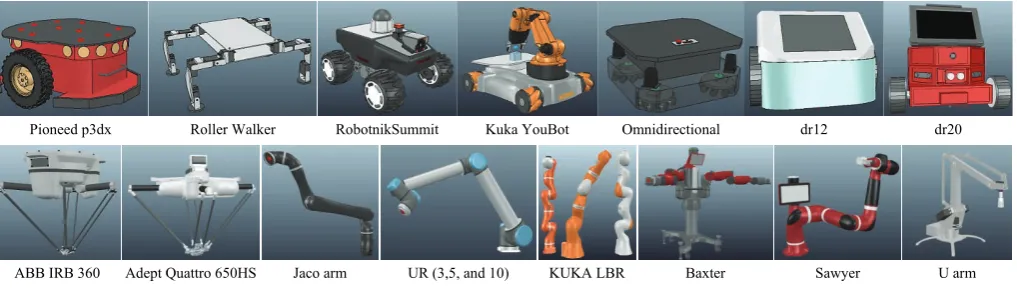
Pioneed p3dx Roller Walker RobotnikSummit Kuka YouBot Omnidirectional dr12 dr20
ABB IRB 360 Adept Quattro 650HS Jaco arm UR (3,5, and 10) KUKA LBR Baxter Sawyer U arm Figure 11 Screenshots of selected V-REP models for mobile and non-mobile robots that can be adapted for use in agricultural simulation
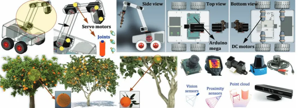
For the purpose of this case study and to show how V-REP functionalities can be extended and scaled from professional robot models to a customized model, we simulated a prototype robot shown in Figure 12 that was not available in the V-REP model library. The ultimate objective was to have a completely simulated robotic platform with different cameras and sensing systems that can perform (i) autonomous navigation and scouting in a virtual citrus orchard, (ii) 3D reconstruction of the environment, (iii) quantification of the fruits, and (iv) estimation of the instantaneous yield from real-time image data. Only a summarized description of this case study is provided here. We began the simulation process by importing CAD models (.STL file) of a prototype mobile robot and a 5-Dof manipulator. Necessary modifications and adjustments, including shape properties, objects grouping and bounding, axis and coordination settings, adding joints and sensors, and customizing physical appearances were carried out on the imported models. Information about preliminary setting and general modifications required prior to a simulation is available in the V-REP manual
of the simulated robot in V-REP.
Our mobile platform was a four-wheel drive and steering field robot that is controlled by four independent DC motors, and a 6-DoF manipulator controlled by six servo motors similar to the one used in [40]. The CAD model of this robot is publicly available for free download from GrabCad webpage of Hossam Mohamed. A similar application of such a mobile platform can be found in [41]. The following main steps were involved in the simulation: (i) creation of workspace, including import, modification, and simulation of the robot CAD model in V-REP (including adding joints, differential drive, and IK tasks), (ii) design and testing of the speed control and navigation system, (iii)
implementing path planning and line following algorithms using V-REP scripts of MATLAB API functions, (iv) experimenting with simulated sensors and camera and importing collected data into MATLAB for image processing, and (v) creating a bidirectional communication (information exchange) between the simulated robot, ROS, MATLAB, and the cameras with the real world. The artificial citrus trees were purchased from greenview3d.com. For the sake of simplicity, we did not simulate the gripper mechanism; hence the manipulator was simulated with five joints representing the five servo motors. The drive and steering subsystem is comprised of four independent wheels and motor units, also known as a differential drive[42].
Figure 12 Major scene objects used in the V-REP case study simulation, including CAD model of a prototype robot platform, artificial citrus trees, and simulated sensors
The robot changes its direction and speed by varying the relative rate of rotation of left and right wheels. For the purpose of simulating the control system in MATLAB, the same numerical value used in [40] was assumed for the DC motors, (that is the moment of inertia of the rotor J=42.6e-6 kg·m2, viscous friction
coefficient b=47.3e-6Nms, torque constant kt=14.7e-3Nm/Amp,
back emf ke=14.7e-3V.s/rad, terminal resistance R=4.67Ω and
electric inductance L=170e-3H). The objective was to control the angular rate of the DC motors (simulated in V-REP by independent joints in torque/force mode) by varying the applied input voltage that is assumed to be proportional to the motor speeds (this was carried out by implementing a PID controller for setting joint target velocity in V-REP). For this objective, the design criteria were defined in such a way that for a step input change of 5 radians per second (s) in the desired joint velocity, the controller satisfies a transient response with settling time of less than 0.5 s, overshoot of less than 5%, and steady-state error of less than 1%. For the inverse kinematics (IK) task of the manipulator, as well as path planning algorithm for the robot navigation, we used V-REP built-in calculation modules. The details of IK setup in V-REP is available in [1]. Descriptions of the path planning algorithm and corresponding set-ups in V-REP are also available as a video demonstration on the AdaptiveAgroTech Youtube channel. The simulated workspace provided a highly configurable, modular robotic system that is capable of adapting to several agricultural tasks and conditions through easy testing and debugging of control algorithms with zero damage risk to the real robot and to the actual equipment.
The vision sensor simulates RGB and gray-scale cameras
(filters are available in V-REP image processing for grayscale or specific R, G, or B band selection), and acquires images at a 512 by 512 pixel resolution. A similar sensor was used for visual servoing from our previous study[1] with inertial measurement filter.
by the pulse to be reflected off and return to the sensor. The frequency-phase shift method measures the phase of multiple frequencies on reflection together with performing simultaneous math calculations to deliver the final measure. Rangefinders are available in V-REP in the form of vision-sensors and proximity
sensors. For example, the Hokuyo URG-04LX-UG01 and the 3D laser scanner range finder use a ray-type laser proximity sensor. Finally, two color cameras were also added for tracking the scene and the position of the robot with respect to the fruit and trees in order to provide a wider view of the simulation scene.
a. Simulation environment for the virtual citrus orchard and the prototype field robot with multiple sensors and obstacle avoidance
b. Scanning with Kinect c. Kinkect sensor: RGB image d. Kinect sensor, depth image e. Scanning with Hokuyo f. Point clouds Figure 13 Using a simulated mobile robot for citrus tree scouting in a virtual orchard, and creating the point clouds of the environment 4.1 Dynamic considerations for realistic simulation
V-rep dynamic modules allow simulating real-world objects interactions in a realistic way such as fruits falling from a tree due to the collision of a vehicle (Figure 14a), or bouncing off the fruits from a conveyor belt or after they are dropped from a harvester gripper (Figure 14b[1]). Physics simulation such as inverse
kinematic is a complex task and can be achieved only to some degree of speed and precision, therefore V-REP dynamics support four physics engines known as the bullet library, the Vortex, the Newton, and the Open dynamics engine. This provides the user with the flexibility for selecting and switching from one engine to the other to satisfy the simulation needs. The bullet library, also known as the video game physic engine, is an open-source engine that supports both soft and rigid body dynamics, as well as three-dimensional collision detection, which are mostly used to provide visual effects in computer games and movies. The Vortex dynamics is a commercial closed source physics engine that provides physics simulation with a high reliability. It offers real-world parameters for simulating various physical properties in a precise and realistic fashion that corresponds to the actual
physical units. Because of these features, Vortex can be used for simulation of agricultural robotics and fruit handling that requires high performance and precision accuracy. An example is the simulation of mass and moment of inertia for sweet pepper fruits that fall on a conveyor belt as shown in Figure 14b. It is notable that the Vortex plugin is not included in the free version of V-REP. It is based on the Vortex Studio Essentials and requires registration with the CMlabs Company (Montreal, QC, Canada) for a free license key. The Newton dynamics implements a deterministic differential equation solver that is not based on classical iterative methods. It is a cross-platform physics simulation library that possesses the stability and speed respectively, making it a tool that is suitable for games and for real-time physical simulation. The Open dynamic is an open-source fully featured physics engine available at www.ode.org/ that is used for general simulation applications as well as games. It is stable, mature, and platform independent and provides an easy to use C/C++ API. It has two main components known as the collision detection and the rigid body dynamics. This engine is especially suitable for simulation field vehicles and objects in the virtual reality environments.
Dynamic data and results of dynamic modules can be recorded and collected using graph objects. While many other simulation packages rely on physics engines that are based on dynamic calculations and approximations and result in a relatively slow and imprecise output, V-REP can be considered a hybrid simulator software that combines both dynamics and kinematics calculations to achieve the most effective performance in different simulation scenarios. For instance, V-REP uses kinematics for robotic manipulators wherever it is possible and relies only on dynamics calculations for the manipulator’s gripper. In the case of simulating the movements and navigation for a crop scouting mobile robot that is operating on a flat field and is not supposed to have physical interaction or collide with the objects of the environment, using kinematics or geometric calculations will result in a much faster and more accurate simulation. It should be noted that the environment in V-REP refers to the properties and parameters, including background color, fog parameters, ambient light, settings, and creation information. These properties are not considered scene objects, but are part of a scene, and are only saved when a scene is saved (not when a model is saved).
4.2 External programming of V-REP (MATLAB and ROS) The main simulation programming script of V-REP contains basic code and functions that are called by the system to runs the simulation. By default, the main script has four functions known as the initialization (sysCall_init), actuation (sysCall_actuation), sensing (sysCall_sensing), and restoration (sysCall_cleanup).
Other than the initialization function that is mandatory, all other functions in the main script are optional. The initialization function is executed only one time right at the beginning of the simulation. The actuation function is executed at each simulation pass and is in charge of handling simulator functionality such as inverse kinematics, as well as lunching threaded and non-threaded child scripts. The sensing function is also executed at each simulation pass and is in charge of handling the sensors (i.e., proximity and vision sensors) or collision detection. The restoration function is executed one time only, right before a simulation is terminated, and is responsible for cleaning and restoring the initial configuration of scene objects, collision, and sensors states. It is notable that the main script is not supposed to be modified, and unless a function is not defined, the call will be ignored. If the main script is modified without having necessary commands, then a model such as a robot manipulator or sensors that are copied into a scene may not perform as expected. As an example of a simple V-REP programming, we illustrate the conventional vision-based navigation control for the prototype scouting robot. Figure 15 shows the sequence of navigation, sensing-and-display, and actuation program for collision avoidance. Here the laser sensor state is read from previous sensing corresponding to the previous simulation pass, then it reacts to the tree. If this sequence is altered, (i.e., sensing, actuation-and-display), the final display data will be different from the actual sensing.
Figure 15 Implementation of laser sensor and Anaglyph stereo sensors in V-REP As mentioned earlier, V-REP supports seven supported
languages: C/C++, Python, Java, Matlab, Octave, Lua and Urbi. For this case study, we used MATLAB as the remote API because it is one of the most widely used programming languages for control tasks and image processing problems. This approach allows controlling the simulation objects (i.e., DC and servo motors) with almost the exact same code as those that run the physical models. The remote API functionality relies on the remote API plugin (on the server side), and the remote API code on the client side. Both programs/projects are open-source (i.e. can be easily extended or translated for support of other languages) and can be found in the 'programming' directory of V-REP's installation. In order to use remote API functionality of V-REP in Matlab program, three files namely (i) remoteApiProto.m, (ii) remApi.m, and (iii) remoteApi.dll were copied from the V-REP's installation directory into Matlab current workspace directory. It is notable that Matlab should uses the same bit-architecture as the remoteApi library. All V-REP remote API functions begin with a prefix "simx”. A list of sample Matlab remote API functions used in the simulation is provided in Table 3. Descriptions of these functions are as follow: (1) simxStartSimulation: requests a start of a simulation, or a resume of a paused simulation, (2) simxGetVisionSensorImage2:
Table 3 MATLAB synopsis for some of the V-REP remote API functions used in the simulation
Remote API function MATLAB synopsis
simxStartSimulation [returnCode]=simxStartSimulation(clientID, operationMode)
simxGetVisionSensorImage2 [returnCode,resolution, image]=simxGetVisionSensorImage2(clientID,sensorHandle,options, operationMode) simxReadProximitySensor [returnCode,detectionState,detectedPoint,detectedObjectHandle,detectedSurfaceNormalVector]
=simxReadProximitySensor(clientID, sensorHandle,operationMode)
simxReadVisionSensor [returnCode,detectionState,auxData,auxPacketInfo]=simxReadVisionSensor(clientID,sensorHandle,operationMode) simxSetJointPosition [returnCode]=simxSetJointPosition(clientID,jointHandle,position,operationMode)
simxSetJointTargetPosition [returnCode]=simxSetJointTargetPosition(clientID,jointHandle,targetPosition,operationMode) simxSetJointTargetVelocity [returnCode]=simxSetJointTargetVelocity(clientID,jointHandle,targetVelocity,operationMode) simxSetVisionSensorImage2 [returnCode]=simxSetVisionSensorImage2(clientID,sensorHandle,image,operationMode) simxStopSimulation [returnCode]=simxStopSimulation(clientID,operationMode)
V-REP implements a ROS node with a plug-in which allows ROS to call V-REP commands via ROS services, or stream data via ROS publishers/subscribers. Publishers/subscribers can be enabled with a service call, and also be directly enabled within V-REP via an embedded script command. The general ROS functionality in V-REP is supported via a generic plugin “libv_repExtRos.so” or “libv_repExtRos.dylib”. It should be noted that plugins are loaded when V-REP is launched, and the ROS plugin will be successfully loaded and initialized only if “roscore” is running at that time. The plugin is open-source and can be modified as much as needed in order to support a specific feature or to extend its functionality. Three of the main ROS package folders in the V-REP, (located in
programming/ros_packages) are the “vrep_common”,
“vrep_plugin”, and “vrep_joy”. The first package is used to generate the services and stream messages that are needed to implement the V-REP API functions, while the second is the actual plugin that is compiled to a “.so” file used by V-REP. The “vrep_joy” package enables interaction with a joystick. Having the services and stream messages in a separate package allows for other application to use them in order to communicate with V-REP via ROS in a convenient way. A ROS package usually includes the followings folders and files: bin, msg, scripts, src, srv, CMakeLists.txt, manifest.xml. The first package is used to generate the services and stream messages that are needed to implement the V-REP API functions, while the second is the actual plugin that is compiled to a “.so” file used by V-REP. The “vrep_joy” package enables interaction with a joystick. Having the services and stream messages in a separate package allows for other application to use them in order to communicate with V-REP via ROS in a convenient way. These packages were copied to the catkin_ws/src folder. The command “$ roscd” was then used to check whether ROS is aware of these packages (e.g., $ roscd vrep_plugin). After navigating to the catkin_ws, the command “$ catkin_make” was used to build the packages and to generate the plugins. The created plugins were then copied to the V-REP installation folder to be used for image subscription and publishing. A new terminal was opened in Ubuntu for staring the ROS master using the command “$ roscore”. Another terminal was opened and was navigated to the V-REP installation folder to launch the V-REP simulator in Ubuntu by typing the command “$ ./vrep.sh”. The entire procedure is summarized as these steps: (i) installing ROS Indigo on Ubuntu and setting up the workspace folder, (ii) copying “ros_packages” in V-REP into the “catkin_ws/src” folder, (iii) source “setup.bash” file, (iv) run “roscore” and “./vrep.sh”. The two available nodes, “/rosout” and “/vrep” and the three topics
“/rosout”, “/rosout_agg”, “/vrep/info” were checked using “$ rosnode list” and “$ rostopic list” commands respectively. In addition, the command “$ rosservice list” was used to advertise all the services. It should be noted that the only V-REP topic that was advertised was “info” publisher that started as soon as the plugin was launched. All other V-REP topics for publishing and subscribing images and sensors were individually enabled using
Lua commands: “simExtROS_enablePublisher” and
“simExtROS_enableSubscriber”. Moreover, to visualize the vision sensor stream images and data, the “$ rosrun image_view image_view image:=/vrep/visionSensorData” and “$ rostopic echo /vrep/visionSensorData” were used respectively. The image subscription and publishing was performed by having V-REP ROS enabled based on ROS Indigo and Catkin build. The general ROS functionality in V-REP is supported via a generic plugin “libv_repExtRos.so” or “libv_repExtRos.dylib”. It is notanle that plugins are loaded when V-REP is launched, and the ROS plugin will be successfully loaded and initialized only if “roscore” is running at that time. The plugin is open-source and can be modified as much as needed in order to support a specific feature or to extend its functionality. Three of the main ROS package folders in the V-REP, (located in programming/ros_packages) are the “vrep_common”, “vrep_plugin”, and “vrep_joy”.