Electromagnetic Linear Microdrive for Braille
Screen: Control and Circuit Test
Dimitar N. Karastoyanov and Vladimir K. Kotev
Institute of Information and Communication Technologies–Bulgarian Academy of Sciences, Sofia, Bulgaria Email: [email protected], [email protected]
Abstract—Graphical interfaces based on visual representation and direct manipulation of objects make the adequate use of computers quite difficult for people with reduced sight. A new type of graphical Braille screen is developed. Permanent magnet linear actuator intended for driving a needle in Braille screen has been optimized. The recently developed permanent magnet linear electromagnetic actuator for driving a needle in a Braille screen and the circuit testing method using micro robots are discussed. Also, a planar and spatial motion tactile display with incorporated electromagnetic linear drives into its links is designed. The optimization is carried out with respect to minimal magnet motive force ensuring required minimum electromagnetic force on the mover. The optimization factors include dimensions of the cores and movable parts under additional constraint for overall dimension of the actuator. Finite element analysis, response surface methodology and design of experiments have been employed for the optimization. The static force characteristics and magnetic field distribution is studied when varying the parameters.
Index Terms—linear actuators, permanent magnets, tactile display, micro robots
I. INTRODUCTION
Permanent magnets have been intensively used in the constructions of different actuators in recent years. One of the reasons for their application is the possibility for development of energy efficient actuators. New constructions of permanent magnet actuators are employed for different purposes. One such purpose is the facilitation of perception of images by visually impaired people using the so called Braille screens. Recently, different approaches have been utilized for the actuators used to move Braille dots [1]-[8]. A linear magnetic actuator designed for a portable Braille display application is presented in [1]. Actuators based on piezoelectric linear motors are given in [2], [3]. A phase-change micro actuator is presented in [4] for use in a dynamic Braille display. Similar principle is employed in [5], where actuation mechanism using metal with a low melting point is proposed. In [6], Braille code display device with a polydimethylsiloxane membrane and thermo pneumatic actuator is presented. Braille sheet display is presented in [7] and has been successfully
Manuscript received January 14, 2014; revised June 6, 2014.
manufactured on a plastic film by integrating a plastic sheet actuator array with a high-quality organic transistor active matrix. A new mechanism of the Braille display unit based on the inverse principle of the tuned mass damper is presented in [8]. Research on development of tactile haptic interface for a Braille display by authors has been studied in the references [9]-[17].
In the present paper, permanent magnet linear actuator for driving a needle (dot) in Braille screen is developed. Methods of circuit testing are discussed. Also, a design concept for planar or 3D motion tactile display driven by electromagnetic linear drives is proposed.
II. DEVELOPMENT OF ALINEARACTUATOR
A. Development of a Linear Magnetic Actuator
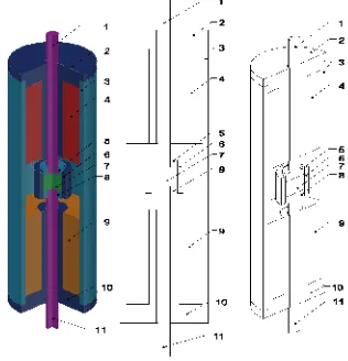
We have developed electromagnetic linear motion actuators for Braille Screen. A CAD model of the linear actuator is shown on Fig. 1.
Figure 1. Electromagnetic actuator 3D CAD model.
Figure 2. A prototype of electromagnetic actuator.
The two coils are identical and connected in series in such a way that they generate a magnetic flux of opposite directions in the region of the permanent magnet. In this way in accordance with the polarity of the power supply, the permanent magnet will move either up or down. When an upward motion is needed, the upper coil creates flux in the air gap coinciding with the flux of the permanent magnet. Lower coil at the same time generates opposite flux and the permanent magnet will move in an upper direction. When a downward motion is needed, the polarity of the power supply is reversed.
One of the main advanced features of the actuator is its increased energy efficiency, as the need of power supply is only during the switching between the two end positions of the mover. In each end position, the permanent magnet creates holding force, which keeps the mover in this position.
B. Performance Simulations of the Linear Actuator
We have performed a finite element modeling in order to study electromagnetic force of the actuator’s performance.
Figure 3. Typical flux lines distribution for three different mover positions.
Axisymmetric model is adopted as the actuator features rotational symmetry. The electromagnetic force acting on the moving permanent magnet is obtained using the weighted stress tensor approach. An example of the flux lines distribution is shown in Fig. 3. In this case, the force on the magnet is in upward direction. More results of this research have been published in papers [9] and [13].
C. Force Determination of the Linear Actuator
Linear displacement and force generated by actuators are important to develop tactile force display. Here, we study the static force parameters of the magnetic based linear actuator. The static force characteristics are obtained for different construction parameters of the actuator. The outer diameter of the core is 7 mm. The air gap between the upper and lower core, and the length of the permanent magnet and the coil heights has been varied. Fig. 4 and Fig. 5 depict the force-stroke characteristics given for different values of the permanent magnet height hm, coil height hw, magneto motive force Iw
and apparent current density in the coils J. Supply of the coils is denoted with c1and c2. The diameter of the mover
is depicted withδ.The coefficients c1=-1, c2=1 represent
the supply for motion up and the pair c1=1 and c2=-1–
motion down. When c1=0 and c2=0, there is no current in
the coil, i.e. this is the force due only to the permanent magnet. More extensive research on the determination of the static forces is conducted and published in the article [14] and [17].
-1.2 -1 -0.8 -0.6 -0.4 -0.2 0 0.2 0.4 0.6 0.8 1 1.2
-0.6 -0.4 -0.2 0 0.2 0.4 0.6
F, N
x, mm
Вариант NV3a (с външен магнитопровод и с горна и долна шайби при височина на ПМ hm=2 mm и въздушна междина δ =3 mm, hw=5mm, Iw=180, J=20А/mm2
c1=-1,c2=1 c1=1,c2=-1
c1=0,c2=0
Figure 4. Force-stroke characteristics for hm=2 (mm), δ=3(mm), hw=5
(mm), Iw=180 (A), J=20(А/mm2).
-1.2 -1 -0.8 -0.6 -0.4 -0.2 0 0.2 0.4 0.6 0.8 1 1.2
-1 -0.5 0 0.5 1
F, N
x, mm Вариант NV3a (с външен магнитопровод и с горна и долна шайби при височина на ПМ hm=4 mm и
въздушна междина δ =6 mm, hw=5mm, Iw=90, J=10А/mm2
c1=-1,c2=1 c1=1,c2=-1 c1=0,c2=0
Figure 5. Force-stroke characteristics for hm=2 (mm),δ=5(mm),
hw=10 (mm), Iw=180 (A), J=10 (А/mm2).
On the basis of our experiments, we can conclude that the major parts of the force characteristics are suitable for Braille screen application. The holding force for the case of hm=2mm, δ=5mm was experimentally verified.
D. Linear Actuator Optimization
cores. As constraints, minimal electromagnetic force acting on the mover, minimal starting force and overall outer diameter of the actuator have been set. The optimization is carried out using sequential quadratic programming. To optimize the linear actuator performance the following parameters ware considered
• NI —ampere-turns—minimizing energy
consumption with satisfied force requirements; • Fh —holding force—mover (shaft) in upper
position, no current in the coils;
• Fs—starting force—mover (shaft) in upper or
lower position and energized coils; • J—coils current density;
• hw, hm, hd—geometric dimensions.
Minimization of magneto-motive force NI is a direct
consequence of the requirement for minimum energy consumption. The lower bounds for the dimensions are imposed by the manufacturing limits and the upper bound for the current density is determined by the thermal balance of the actuator.
The radial dimensions of the construction are directly dependent on the outer diameter of the core – D whose
fixed value was discussed earlier. The influence of those parameters on the behavior of the construction have been studied in previous work [15], [16] that make clear that there is no need radial dimensions to be included in the set of optimization parameters Fig. 6.
-0.4 -0.3 -0.2 -0.1 0 0.1 0.2 0.3 0.4 0
0.1 0.2 0.3 0.4 0.5 0.6 0.7 0.8
x, mm
F
,
N
FORCE-STROKE characteristic (energized coils)
Fh - force switches to the holding force when current is ceased F - final force (shaft imoved in lower position, coils still energized)
Fs - starting force (shaft in upper position)
Figure 6. Force-stroke characteristic of the optimal actuator. Coils are energized. The shaft is displaced from final upper to final lower position.
The force constraints for Fs and Fh are active which
can be expected when minimum energy consumption is required. The active constraint for hw is also expected
because longer upper and lower cores size, which respectively means longer coils, will increase the leakage coil flux and corrupt the coil efficiency.
In (Fig. 7 and Fig. 8), the magnetic field of the optimal actuator is plotted for two cases. The first one is magnetic field of the optimal actuator with shaft in upper position and coils energized to create downward force (Fig. 7). In the second case, coils are not energized (Fig. 8). More results of this research have been provided in papers [16] and [17].
Figure 7. Magnetic field of the optimal actuator with shaft in upper position and energized coils.
Figure 8. Magnetic field of the optimal actuator with no current in the coils.
III. DEVELOPMENT OF ALINEARACTUATOR
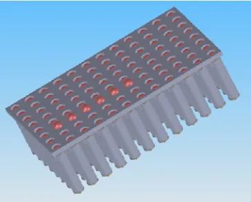
A tactile matrix for Braille screen is designed (Fig. 9) and developed (Fig. 10). The developed electromagnetic linear motion micro actuators (Fig. 2) discussed into the previous chapter is put into the matrix (Fig. 10).
Figure 10. A prototype of a Braille screen with needles (dots) driven by linear actuators.
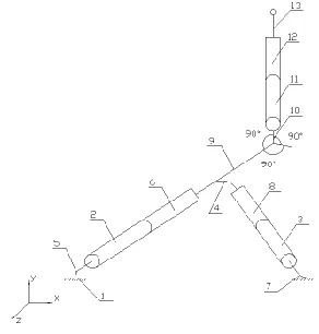
For better resolution of the graphical images the Braille screen must be larger, for example 96x64 linear micro drives (pixels). It is more than 6000 elements in human hand size with 4 coil connectors for each. In this case we need a strong electro-mechanical test of the entire circuit. We plan to use micro robots for positioning and testing, [15]-[19]. We are developing a smart micro robot with 3 DoF (Degree of freedom) and piezo effectors. Its structural scheme is shown on (Fig. 11). This micro manipulator consists of 1-base; 2, 3, 11-mobile links; 4, 5, 7-elastic connections; 6, 8, 12-piezo actuators; 9, 10-hard connections; 13-sensing element.
Figure 11. Micro manipulator with 3 DoF and incorporated electromagnetic actuators into its links.
A. Desing and Modeling of a Tactile Display
We have been developing tactile force displays based on electromagnetic linear motion actuators. Generally, planar and spatial motion tactile devices (Fig. 12 and Fig. 13) are being designed and modeled. In this research the designed tactile mechanisms will be used for development of Braille screen. More in particular, we are focused on the design of mechanisms with close kinematic chain (CKC) driven by electromagnetic actuators. The main advantages of this type of mechanisms are: considerable decrease in the weight of mechanical systems; reduced inertial forces–increased accuracy; reduced backlashes when links are connected by revolute joints. Also, there are some disadvantages typical for them, such as compensation of the hysteresis.
In addition, mechanisms with CKC and incorporated actuators into their links could be used for precise linear motion mechatronics systems and robots. Geometrical syntheses of 3 DoF planar mechanisms are discussed below.
Figure 12. Structural scheme of 3 DoF mechanism with electromagnetic actuators.
Figure 13. Structural scheme of 2 DoF mechanism with electromagnetic actuators.
In the structural schemes (Fig. 12 and Fig. 13) electromagnetic driven links are illustrated as prismatic pairs. λ1 and λ2 represent linear displacement of the
H-H´ of the mechanism’s output link, the problem will be solved if the following are given:
• Linear equation;
• Angle of the slope of the straight line; • Linear equation passing through 2 points.
We assume that the slope of line (к) i.e. necessary linear trajectory) is given:
tgγ =
k (1)
whereγis a given slope of the line
' H H ' H H HH' x x y y = K − − (2) θ l + y = y θ, l x =
x C 'H
' H
c − *cos *sin (3)
δ) ( l y = y δ), ( l x =
xA C −2cos − A C −2sin − (4)
In order to control the designed tactile devices with CKC mechanisms or micro motion manipulator the Forward and Inverse kinematics are required. The dynamics of the tactile devices could be derived easily from the equations from (1) to (3). After that the transfer function will be defined. We define the relations between the driving force of the actuators and the displacement of the construction and the end-effector of manipulators (Fig. 13). Also, the stress and stiffness of the constructions due to actuators forces are found.
IV.CONCLUSIONS
Braille screen interface causing force sensation on the user’s hand has been developed. Electromagnetic linear motion micro actuators are developed and manufactured to drive the tactile Braille screen. The permanent magnet linear actuator is intended to drive a needle in Braille screen. The mover of the actuator consists of a permanent magnet and ferromagnetic discs. Moreover, we have studied and optimized this magnetic based linear actuator. The optimization is carried out with respect to minimal magnet motive force ensuring required minimum electromagnetic force on the mover. The optimization factors are dimensions of the cores and mover parts under additional constraint for overall dimension of the actuator. In addition, to achieve better dynamics and construction of the linear actuator finite element method analysis has been done. Many experimental tests have been done on electromagnetic linear actuator in order to control Braille screen. The obtained results of our research show that actuator’s static force characteristics are suitable for Braille screen application. We have been working on the control of the developed Braille screen.
To achieve better contact force representation on the user’s hands mechanisms with closed kinematic chain and actuators incorporated into their links have been
designed. We are developing a tactile force display based on these mechanisms.
ACKNOWLEDGMENT
This work was supported in part by the project Advanced Computing for Innovation - AComIn, grant 316087, funded by the FP7 Capacity Programme (Research Potential of Convergence Regions).
REFERENCES
[1] T. Nobels, F. Allemeersch, and K. Hameyer, "Design of a high power density electromagnetic actuator for a portable braille display," in Proc. International Conference EPE-PEMC, Cavtat & Dubrovnik, Croatia, 9-11 September, 2002.
[2] H. Cho, B. Kim, J. Park, and J. B. Song, "Development of a braille display using piezoelectric linear motors," in Proc. International Joint Conference SICE-ICASE, Busan, South Korea, 2006, pp. 1917-1921.
[3] H. Hernandez, E. Preza, and R. Velazquez, "Characterization of a piezoelectric ultrasonic linear motor for braille displays," in Proc. Electronics, Robotics and Automotive Mechanics Conference CERMA 2009, Cuernavaca, Mexico, 2009, pp. 402-407.
[4] S. Green, B. Gregory, and N. Gupta, "Dynamic braille display utilizing phase-change microactuators," in Proc 5th IEEE Conference on Sensors, Daegu, Korea, 2006, pp. 307-310. [5] C. Chaves, I. Peixoto, A. Lima, M. Vieira, and C. J. de Araujo,
“Microtuators of SMA for braille display system,” presented at IEEE International Workshop on Medical Measurements and Applications- MeMeA, 29-30 May 2009, pp. 64-68.
[6] A. Kwon, S. W. Lee, and S.S. Lee, “Braille code display device
with a PDMS membrane and thermo pneumatic actuator,”in Proc.
21st IEEE International Conference on Micro Electro Mechanical Systems MEMS 2008, JW Marriott Starr Pass Resort & Spa Tucson, AZ, USA, 2008, pp. 527-530.
[7] Y. Kato Y. et al., "A flexible, lightweight braille sheet display with plastic actuators driven by an organic field-effect transistor active matrix," IEEE International Electron Devices Meeting, 2005.
[8] Y. Kawaguchi, K. Ioi, and Y. Ohtsubo, "Design of new braille display using inverse principle of tuned mass damper," in Proc. SICE Annual Conference, Taiwan, 2010, pp. 379-383.
[9] I. Balabozov, I. Yatchev, K. Hinov, and D. Karastoyanov,
"Influence of different factors on the static force characteristics of a permanent magnet linear actuator for braille screen," in Proc. SIELA Conference, Burgas, Bulgaria, vol. 2, 2012, pp. 20-26. [10] D. Karastoyanov, "Braille screen," Bulgarian Patent Announce
110731, August 10, 2010.
[11] D. Karastoyanov and S. Simeonov, "Braille display," Bulgarian Patent Announce 110794, November 11, 2010.
[12] D. Karastoyanov, I. Yachev, K. Hinov, and T. Rachev, "Braille screen," Bulgarian Patent Announce 111055, October 13, 2011. [13] I. Yatchev, K. Hinov, V. Gueorgiev, D. Karastoyanov, and I.
Balabozov, "Force characteristics of an electromagnetic actuator for braille screen," in Proc. International Conference on Electrical Machines, Drives and Power Systems ELMA 2011, Varna, Bulgaria, 2011, pp. 338-341.
[14] I. Yatchev and D. Karastoyanov, "Optimization of permanent magnet linear actuator for braille screen," presented at the International Symposium IGTE 2012, Graz, Austria September 16-18, 2012, pp. 59-63.
[15] S. Simeonov and N. Simeonova, "Graphical interface for visually impaired people based on bi-stable solenoids," International Journal of Soft Computing and Software Engineering, vol. 3, no. 3, pp. 844-847, 2013.
[16] S. Simeonov, N. Simeonova, and A. Iliev, "Deterministic model of CPU scheduling in real time operating system," in Proc. Confer. UNITECH-13, Gabrovo, Bulgaria, 2013, pp. 192-197.
[18] V. Kotev and D. Karastoyanov, "Micromanipulator for inspection
of shafts coating with nano components," in Proc. 1st
International Conference on Manipulation, Manufacturing and Measurement on the Nanoscale 3M-NANO, Changchun, China, 2011, pp. WE19.1-WE19.4.
[19] P. Genova, K. Kostadinov, V. Kotev, and T. Tyankov, "Micro-electro-mechanical device for manipulators," Bulgarian Patent Announce 110597, 2010.
Dimitar N. Krarastoyanov is a member of
the Bulgarian Scientists Association. He was born in Stara Zagora, Bulgaria in 1952. He has a master degree in Electrical engineering. He graduated from the Technical University Sofia in 1977. The author received a doctoral degree in 1982 in Robotics from the Institute of engineering cybernetics and robotics (BAS). Dr. Karastoyanov is a professor at the Institute of Information and Communication Technologies (BAS). Prof. Dr. Karastoyanov is a key professor under AcomIn project at the IICT– BAS. He is conducting research on design, dynamics and intelligent control of
robots and mechatronic systems. His professional interests refer to real time systems, adaptive control, industrial engineering and robotics.
Vladimir K. Kotev is a member of the
Bulgarian Scientists Association. He was born in Sliven, Bulgaria in 1976. He has a Master degree in Mechanical engineering. He graduated from the Technical University Sofia in 2002. After that he worked in a private machine building company for 2 years. Next, the author received a doctoral degree in 2008 in Biomechanics from the Institute of Mechanics at the Bulgarian Academy of Sciences (BAS). Dr. Kotev is an assistant professor at the Institute of Mechanics. He has been a postdoctoral researcher in medical robotics at the Kawasaki and Mori
laboratory at Gifu University–Japan from 2011 to 2013. Dr. Kotev is a