ABSTRACT
DOSHI, JIMIT. Framework for the Integration of Distributed Energy Storage Device with the Future Renewable Electric Energy Delivery and Management System. (Under the direction of Dr. Srdjan Lukic.)
The Future Renewable Electric Energy Delivery and Management (FREEDM) System is a
revolutionary concept in revamping the grid infrastructure and making the move towards Smart
Grids. It envisions a distributed electric energy system that supports bi-directional power flow
with the grid, coupled with the intelligence to make optimal use of such distributed resources
from an economic and electric standpoint.
The FREEDM System consists of several localized Energy Cells made of one or more
renewable energy generation and storage devices which are governed by distributed and
intelligent energy management algorithms. Energy storage devices, based on batteries and super
capacitors, shall play a vital role in such a distributed system to act as local reservoirs of energy
that can be utilized for applications such as peak shaving, frequency regulation, load levelling
etc. The operation and control of such a Distributed Energy Storage Device (DESD) thus
depends on its control and communication interface with other devices within the Energy Cell.
This thesis presents a comprehensive framework to integrate a DESD within the FREEDM
Energy Cell. It involves defining a standardized command and status interface, called the ’Device
Profile’, which it can share with any other device on the network. We implement an end to end
communication network between the DSPs (that directly interact with the hardware of the
DESD) and the external entity that seeks to control the DESD. We make judicious choice
of various communication protocols such as MQTT, MODBUS and IEEE 802.15.4 based on
RF that make this network, considering not only system requirements but also their scalability,
portability and acceptance in the industry. In this regard, the DESD is used as a template device
an embedded systems perspective. We arrive at a two-tier solution consisting of the DSPs to
directly control the power electronics and a central single board computer such as the Beagle
Bone Black (BBB) that acts as a communication gateway and also an application development
platform. This scheme is generic and suitable enough for all the power converter devices within
the FREEDM Energy Cell, and not just the DESD.
Using the BBB platform and a battery data acquisition system, we implement a State of
Charge (SoC) estimation algorithm for the DESD which helps us track it’s energy reserve
capacity in real time. Based on this we develop other application such as SoC Balancing between
the batteries of DESD and also Integration with a Smart Home system. We also characterize the
performance of the DESD by measuring parameters such as communication latencies, reference
Framework for the Integration of Distributed Energy Storage Device with the Future Renewable Electric Energy Delivery and Management System
by Jimit Doshi
A thesis submitted to the Graduate Faculty of North Carolina State University
in partial fulfillment of the requirements for the Degree of
Master of Science
Electrical Engineering
Raleigh, North Carolina
2015
APPROVED BY:
Dr. David Lubkeman Dr. Iqbal Husain
DEDICATION
To my parents
BIOGRAPHY
Jimit Doshi was born on October 2, 1987 in the city of Bhavnagar (Gujarat), India.
He received the Bachelor of Engineering (B.E.) degree in Electronics Engineering from the
K .J. Somaiya College of Engineering, University of Mumbai, in 2009. Subsequently he worked
as a Senior Embedded Design Engineer at Sprylogic Technologies Ltd. (Thane, 2009 - 2012)
and as a Senior Software Engineer at Robert Bosch Engineering and Business Solutions India
Ltd.(Coimbatore, 2012 - 2013).
Jimit joined the Electrical and Computer Engineering Department of North Carolina State
University in August 2013 to pursue the Master of Science (M.S.) degree in Electrical
Engineering. He has been working with the Future Renewable Electric Energy Delivery and
Management (FREEDM) Systems Center under the guidance of Dr. Srdjan Lukic since January
2014. He worked at Makani Power (Google[x]) as a Hardware Engineering Intern from June to
August 2014.
His research interests include Embedded Systems and Power Electronics. After his graduation
ACKNOWLEDGEMENTS
I thank Dr. Srdjan Lukic for giving me the opportunity to work on this Thesis. Your complete
support and faith in me since I joined the FREEDM Center has given me the confidence to
pursue this Thesis to the best of my abilities. I shall always remember the numerous insightful
discussions we have had over the past year as they have always been a great source of learning.
I sincerely appreciate your patience with me when things wouldnt necessarily go as planned.
I thank Dr. David Lubkeman for guiding me as a part of the Software Team responsible for
the Green Energy Hub (GEH) Demonstration. It wouldnt have been possible to make all the
appropriate design choices for architecting the communication network if not for your helpful
suggestions and deep understanding of the system requirements.
I express my gratitude to Dr. Iqbal Husain for agreeing to be a part of my committee and
efficiently leading the FREEDM Center over the past year.
Thank you Siddhartha for handling the MQTT backend and a lot many other things. It was
great fun working with you. Thanks Habib for often taking out the time in spite of your hectic
schedule for guiding me with the implementation of SoC algorithm. I thank Youxi Shao for
introducing me to the project and Chi and Xinyu for assisting me with the design and testing
of hardware.Thanks Aakash and Heinrich for assisting me with data processing. A special thanks
to Karen, Hulgize and Greg : you guys leave no stone unturned to make FREEDM a resourceful,
safe and friendly place to work at.
Nirmal and Bhumi, I wouldnt be here without you. Thanks for your unwavering confidence
in me and for always ensuring my well being.
Saurabh and Rohan, thanks for always being there. We have come a long way from where
we began.
Bhavin and Manasi, I never missed my family when I was around you guys. Thanks for
being with me through all the ups and downs. Soumya, thanks for all your guidance time and
Neha, this thesis wouldnt be the same without you. Thanks for keeping me motivated.
To all my friends and colleagues : I have learnt something from each one of you and am glad
that our paths crossed at some point of time.
I would like to express my sincere appreciation to my extended family : my aunts, uncles,
cousins, nephews and nieces. I cannot thank you enough for your love and blessings.
Mom and Dad, I shall be eternally grateful for all your love and sacrifices for me. I thank you
for your patience and understanding. I will always be indebted to you for your unconditional
faith in me. Parth, even the shortest chat with you would lighten up my day and I feel blessed
TABLE OF CONTENTS
LIST OF TABLES . . . .viii
LIST OF FIGURES . . . ix
Chapter 1 Introduction . . . 1
1.1 The FREEDM System . . . 2
Chapter 2 Design and Operation of Distributed Energy Storage Device . . . . 6
2.1 System Design . . . 7
2.1.1 Cascaded H-Bridge Series Inverter System . . . 9
2.1.2 Battery Management System . . . 11
2.1.3 Communication and Application Development Platform . . . 14
2.2 System Operation . . . 21
Chapter 3 Communication Architecture for DESD. . . 24
3.1 DESD Architectural Configurations . . . 25
3.2 Evaluation of M2M and IoT Messaging Protocols . . . 28
3.3 Architecture and Implementation of the MQTT based Communication Network . 31 3.3.1 Architecture of the FREEDM MQTT Network . . . 31
3.3.2 Implementation of the MQTT based Communication Network . . . 33
3.4 Performance Test of the Communication Network . . . 40
3.4.1 Test A: Network of Two Devices . . . 40
3.4.2 Test B: Network of Three Devices . . . 43
Chapter 4 Applications Developed for DESD . . . 46
4.1 State of Charge Estimation . . . 46
4.1.1 Determining the Ahbattmax . . . 48
4.1.2 SoC Estimation Algorithm . . . 48
4.1.3 Validation . . . 54
4.2 State of Charge Balancing Algorithm . . . 54
4.3 Integration with a Home Energy Management System . . . 59
Chapter 5 Performance Benchmarking Tests for the DESD . . . 61
5.1 Reference Signal Tracking . . . 61
5.2 Response Time and Ramp Rate . . . 62
Chapter 6 Conclusion . . . 64
6.1 Accomplishments . . . 64
6.2 Future Work . . . 65
BIBLIOGRAPHY . . . 66
Appendix A Serial Communication Commands . . . 71
A.1 DESD Turn ON Sequence . . . 72
A.2 DESD Turn OFF Sequence . . . 72
A.3 Power Dispatch Commands . . . 72
A.4 System Parameter Polling Commands . . . 74
A.5 Modbus Polling for BMS . . . 75
Appendix B Xbee Configuration for Master - Slave Operation . . . 76
B.1 Xbee Master Configuration . . . 77
B.2 Xbee Slave Configuration : Rx and Tx Enabled . . . 77
B.3 Xbee Slave Configuration : Only Rx Enabled . . . 78
LIST OF TABLES
Table 3.1 Test Results for Communication Latency between two Clients representative
of a DESD and an SST . . . 42
Table 3.2 Test results for communication latency between three clients representative of a DESD, SST and a Data Concentrator . . . 43
Table 5.1 Reference Tracking Performance of DESD . . . 62
Table A.1 DESD Turn ON Sequence . . . 72
Table A.2 DESD Turn OFF Sequence . . . 73
Table A.3 Charge / Discharge Direction Command for DESD . . . 73
Table A.4 Sample Power Command Dispatch Frames . . . 74
Table A.5 Polling Commands for System Parameters . . . 74
Table A.6 Range of Modbus Data Points for each Battery . . . 75
LIST OF FIGURES
Figure 1.1 Electric grid with key elements of the FREEDM System. Adapted from [1] . 3 Figure 1.2 Functional Diagram of an SST. Adapted from [1] . . . 4
Figure 2.1 System Block Diagram of DESD . . . 8 Figure 2.2 Topology of Cascaded H-Bridge DESD. Adapted from [2] . . . 9 Figure 2.3 Power Stage System Configuration of Cascaded H-Bridge DESD. Adapted
from [2] . . . 10 Figure 2.4 Cell Composition Structure of the Battery . . . 11 Figure 2.5 Functional Block Diagram of LTC6803-2. Adapted from [3] . . . 13 Figure 2.6 (a) RC Filter Circuit for Cell Module Voltage Detection and (b) RC Filter
Circuit for Battery Current Detection . . . 13 Figure 2.7 Complete setup of BMS system . . . 14 Figure 2.8 Single SPI Master communicating with multiple Slaves over an isolated
network. Note the need for a dedicatedCS signal for each Slave . . . 17 Figure 2.9 Single I2C Master communicating with multiple Slaves over an isolated
network. SDA (Data) line is bidirectional requiring sophisticated isolation provisioning . . . 18 Figure 2.10 Multi node isolated CAN bus . . . 18 Figure 2.11 Modbus Communication over Serial Line (UART) using XBee . . . 20 Figure 2.12 (a)Beagle Bone Black. Adapted from [4] and (b) XB24-AWI-001. Adapted
from [5] . . . 21 Figure 2.13 System operation with a two-tier controller scheme . . . 23
Figure 3.1 SSTs directly controls their respective DESDs as a means to match demand-supply constraints. The DGI software manages IEM algorithms on SST to control the power flow operation . . . 25 Figure 3.2 DESD as a part of a smart home, controlled by an intelligent HEMS . . . 26 Figure 3.3 Example of an MQTT Network using hierarchical topics to organize messages 32 Figure 3.4 Multi-Tiered Network Architecture of the FREEDM System . . . 34 Figure 3.5 Device Profile of a DESD . . . 35 Figure 3.6 Data flow path between an SST and DESD over the MQTT Network . . . . 37 Figure 3.7 Hardware - software platforms for different test cases in a two device network 41 Figure 3.8 Test setup for a three device network . . . 44
Figure 4.1 Calculation of the residual energy capacity in the DESD based on the SoCs of cell modules that make a battery . . . 48 Figure 4.2 Charge characteristics for a fully discharged battery cell module to calculate
it’s Ah capacity. Blue lines demarcate the integration limits for charging current against time . . . 49 Figure 4.3 Battery Model with interal resistance, relaxation effect and Voc - SoC
Figure 4.5 SoC, Charging current and Voltage for a cell module approaching full charged state. The intermittent fall in current readings can be attributed
to measurement noise . . . 53
Figure 4.6 Block Diagram for SoC Balancing Algorithm . . . 57
Figure 4.7 Convergence of Battery Pack SoCs during a discharge operation . . . 58
Figure 4.8 Integration of DESD with the HEMS System . . . 60
Figure 5.1 Response Time and Ramp Rate Calculation. Adapted from [6] . . . 63
Figure 5.2 Response Time observed for the DESD . . . 63
Chapter 1
Introduction
The existing electric grid infrastructure, deployed several decades ago, has essentially
remained the same over the years in terms of its architecture and design. The fundamental law
governing its design was to transfer power from a centralized generation system to the end user
through a series of distribution transformers. While this infrastructure has served us well over
the years, it is not suitable to support a number of recent developments in the power generation
and distribution domain. Firstly, the world is making a slow transition to utilizing
non-conventional energy resources, such as wind and solar power, thanks to increasing environmental
consciousness and the realization that conventional energy resources such as coal and gas are
fast depleting. However, the intermittent nature of such renewable energy resources can cause
serious stability issues with the grid [7, 8, 9], unless we have a better forecast data acquisition
mechanism in place : something thats absent from the existing grid infrastructure. Secondly,
these non-conventional energy resources need not necessarily be deployed in a centralized fashion
with large capacities, but rather they can be distributed in space, closer to the end user and
in smaller capacities. Such a distributed power generation architecture goes against the design
philosophy of existing grid which was meant to support only a unidirectional power flow .
Thirdly, the power grid infrastructure has largely remained insulated from the tremendous
We need to integrate these ICT technologies with the grid infrastructure to reap the benefits
of real time data gathering, big data analytics and robust control.
This recognition that the needs of the 21st century are vastly different from the ones that the
existing grid infrastructure was designed to serve, has led to extensive interest in the concept of
Smart Grids (SG). The National Institute of Standards and Technology defines Smart Grid as “a
modernized grid that enables bidirectional flows of energy and uses two-way communication and
control capabilities that will lead to an array of new functionalities and applications”[10]. So SG
shall be an enabling technology to allow bi-directional flow of both power and communication.
It involves redesigning the hardware at each stage of transmission and distribution network
to support a bidirectional power flow and redefining the terms of engagement between various
devices that form this network which connects the end user to the grid. An SG shall allow easy
integration of renewables to the electric grid by being adaptive enough to their dynamic nature
while at the same time better managing the supply-demand constraints in real time.
1.1
The FREEDM System
The Future Renewable Electric Energy Delivery and Management (FREEDM) System [11] as
being developed at the North Carolina State University and its partner universities, essentially
envisions such an Energy Internet that is architected to allow automated and flexible electric
power distribution. Power converters such as the Solid State Transformer (SST), Distributed
Renewable Energy Resource (DRER) and Distributed Energy Storage Device(DESD) form the
building blocks of FREEDM Systems power flow scheme. Figure 1.1 from [1] shows a possible
layout of a FREEDM system. The DRER, DESD and loads are connected to an SST that
also hosts an Intelligent Energy Management (IEM ) subsystem. The SST is a three port
energy router that consists of a high voltage AC port and low voltage AC and DC ports
(Figure 1.2). It not only performs the voltage step down function but also serves to route
(DGI) [12] software and communication interfaces uses the SST as the underlying hardware
to serve as a power exchanger and an energy router. There can be several small and modular
DRERs (powered by solar panels or wind turbines) and DESDs (based on batteries of any
chemistry or even those of plug in hybrid vehicles or supercapacitors) that are connected to
an SST and governed by the IEM algorithm(s) running on that SST. Such a cluster of power
converters whose operation is governed by a local intelligence system, be it IEM or even a Smart
Home Management System (for residential users) can be called an Energy Cell. The FREEDM
grid is then composed of several such Energy Cells, each of whom try to achieve an optimal
electric and economic performance at any given point of time. Considerable work has been
Figure 1.1 Electric grid with key elements of the FREEDM System. Adapted from [1]
done in the area of designing power electronics and control strategies for and amongst each
of these converters, but the communication interface between them has been rather loosely
defined. While a Distributed Grid Intelligence (DGI) Operating System that would allow peer
Figure 1.2 Functional Diagram of an SST. Adapted from [1]
communication link within an Energy Cell governed by such a DGI node that is still missing.
This thesis identifies the communication needs specifically for a device that is meant to
operate within an Energy Cell. We use a 1 kW / 2.7 kWh DESD as a template device
while proposing a comprehensive framework to connect the different devices within an Energy
Cell. While all the testing and validation for the proposed communication design has been
performed with the said DESD, it is portable and generic enough to be adopted by any of the
other devices(such as a DRER) in the energy cell. Additionally, this thesis also demonstrates
the development of multiple applications that can be deployed on the DESD to support
it’s various possible use cases with the FREEDM System. Finally we also derive certain
performance parameters for characterizing the DESD in order to provide a complete picture of
it’s performance to any entity that seeks to control it.
The remainder of this thesis is organized as follows : Chapter 2 describes the DESD design
and operation in detail. This DESD hardware was first developed by Sanzhong Bai [2]. That
setup has since been enhanced to a higher power rating and energy capacity. It also describes
the design of a battery data acquisition system which collects the raw data to estimate the
State of Charge (SoC) of the batteries. A two-tier embedded controller solution consisting of
meeting all the computational and communication needs of the DESD. The choice of Modbus
protocol for communication within the DESD (between the DSPs and the BBB) is also justified
here. Chapter 3 details the role of the DESD in a FREEDM system and the different use cases
it might need to support. Requirements for a suitable external communication interface are
identified and addressed by assessing the relevant industry standard protocols. Message Queue
Telemetry Transport (MQTT), a messaging layer communication protocol based on TCP/IP is
finally chosen and implemented after a careful consideration of system requirements. Relevant
implementation details and test results are discussed. Chapter 4 elaborates on the algorithm
and implementation details for three different applications viz. State of Charge Estimation,
State of Charge Balancing and Integration with a Home Energy Management System (HEMS),
that we have demonstrated to work with the DESD. In Chapter 5 we present the results of some
characterization tests performed on the DESD to benchmark its performance. Finally Chapter
6 concludes the thesis with a summary of the accomplishments and suggesting a road map for
Chapter 2
Design and Operation of Distributed
Energy Storage Device
Conventional energy storage installations have used mechanisms such as pumped
hydro-storage, compressed air hydro-storage, spinning flywheel and lead acid or sodium sulphur based
batteries[14]. While these are suitable for a large scale, centralized or utility controlled
installations, not all of them scale down well to support a distributed architecture with smaller
capacities. Battery based solutions, albeit of varying battery chemistries, dominate this space
due to their ubiquitous availability and easy scaling. While lead acid has typically been the
dominant battery type in all kinds of industrial applications, a lot of recent efforts have been
focused on exploring other battery chemistries for energy storage applications to achieve higher
energy density without compromising on safety and reliability[15, 16, 17, 18].
This chapter gives an overview of the design and features of the DESD used for this work.
The modular control scheme of the DESD as described in Section 2.1 lends itself well to having
low voltage batteries of different chemistries and capacities in the same unit. Currently the unit
is powered with Li-ion batteries reclaimed from Hymotion L5 conversion module for a Toyota
port of any power system. So as a part of the FREEDM Energy Cell, it can be interfaced to
the 120 V AC port of an SST (at a community level) or it may also be used directly by the
residential end user as a part of a Smart Home. It also incorporates a Battery Management
System (BMS) that provides real time battery cell module voltage, current and temperature
data to estimate the State of Charge (SoC) of the batteries. The relevant architecture and
implementation details are described in the sections below.
2.1
System Design
With reference to Figure 2.1 below, the DESD broadly consists of 3 sub-systems that work
in tandem to deliver the overall functionality :
1. Cascaded H-Bridge Series Inverter System : Consists of power electronics, sensors and
grid interface.
2. Battery Management System : Consists of analog front end and a DSP to acquire raw
data of cell voltage and current from each battery in the system
3. Communication and Application Development Platform : Consists of an ARM based single
board computer, the Beagle Bone Black (BBB), to run native algorithms and also act as
2.1.1 Cascaded H-Bridge Series Inverter System
The AC DESD device uses a cascaded H-bridge topology as described in [2, 19] . In Figure 2.2
each block represents a modular and bi-directional H-bridge inverter interfaced to it’s battery.
In the actual set up elaborated in Figure 2.3, four such converters are connected in series so
that they share the AC current while their respective AC voltages add up to form the interface
voltage with the grid (via a 1:2.5 transformer). The main advantages of such a topology are as
below :
1. Modular design with independent control of each module.
2. Batteries with dissimilar chemistries and potentials can be combined in a single unit.
3. No need of a centralized controller, which leads to a scalable architecture.
4. No need for communication between modules as each of them independently follow their
own control law.
Figure 2.3 Power Stage System Configuration of Cascaded H-Bridge DESD. Adapted from [2]
The overall control strategy is as below:
1. Module 1 solely controls the AC current that flows through the series string of H-bridge
converters. The reference signal for this AC current is derived from the power dispatch
command and the sensed grid interface voltage.
2. Modules 2, 3 and 4 control their respective additive contributions in sharing the grid
interface voltage. The overall grid interface voltage is thus the sum of those generated
by modules 1 to 4, but directly controlled by only modules 2, 3 and 4 (since module 1
operates with AC current as the control parameter). The voltage contribution of any of
modules from 2, 3 and 4 is directly proportional to it’s net power contribution to the total
power command. Thus, in the simplest case when all the modules are sharing the total
power equally amongst themselves, the voltage reference for each of the modules 2, 3 and
4 is also equal.
All the modules receive the isolated signal for grid interface voltage. They natively apply
zero crossing detection to achieve phase synchronization of their respective sinusoidal PWM
generation signals. The digital control of this system is performed by a DSP (TMS320F28335,
The above work was accomplished by Sanzhong Bai as a part of his PhD dissertation. A
complete formal description of the control strategy with additional implementation details can
be found in [2, 19].
2.1.2 Battery Management System Architecture
The DESD consists of four H-bridge converters, each supported by a stack of two Lithium
ion batteries in parallel. Thus the system consists of a total of eight batteries. We have two
batteries in parallel for each H-bridge module to raise the system capacity and provide better
transient response, considering that the batteries being used are reclaimed ones.
Each battery consists of a series string of eight cell modules, each rated for 3.3 V nominal.
Each of these cell modules physically consists of eleven ANR26650M1A cells (A123 Systems
[21]) in parallel. The cell composition structure that makes up a battery is thus shown below
in Figure 2.4 The analog front end to acquire raw data of module voltages and current for each
Figure 2.4 Cell Composition Structure of the Battery
battery is based on the LTC 6803-2 IC (Linear Technologies [3]. It is designed to perform analog
to digital conversion of sensed battery parameters from a stack of battery cells. A PCB board
is mounted on each of the batteries. A single DSP controller communicates with all of these
BMS boards to acquire raw data of cell voltages and battery currents. The LTC 6803-2 IC
supports Serial Peripheral Interface (SPI) communication protocol, so all the BMS boards are
connected over a shared SPI bus with the DSP. Since the LTC 6803-2 IC also has provision for
4 bit addressing, it’s easy to individually address each of the BMS boards by assigning them
a unique 4 bit address in hardware. The DSP then polls each of the BMS boards in a cyclic
manner to gather the raw data associated with it’s battery.
Implementation
This section describes the hardware implementation details for the BMS system.
The BMS board is capable of measuring all the eight cell module voltages, the net battery
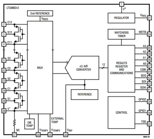
current and also ambient temperature. As seen in the functional diagram of the LTC 6803-2 IC
[3] in Figure 2.5, it has provision to measure cell voltages of upto 12 stacked cells in any battery.
We use it for monitoring the 8 cell modules of the battery used by this DESD. A simple low
pass RC filter with cut-off frequency of 16 kHz (R = 100 Ω, C = 0.1 µF) recommended in [3]
as optimal, is used for cell voltage measurement (Figure 2.6a).
The LTC 6803-2 also has provision for interfacing two external temperature sensors at
terminals VT EM P1 and VT EM P2. We use one of those terminals for actually interfacing a Hall
Effect current sensor, ACS759LCB-050B (Allegro MicroSystems LLC, [22]) , to measure the
battery current. However, the battery current is actually not a clean DC signal, but rather a
rectified sinusoidal signal with 60 Hz as the dominating fundamental frequency. This is because
the battery is directly interfaced with the H-bridge converter. Since we are interested in the
average value of the signal for calculating the SoC of the batteries, we feed the signal to a
low pass RC filter with a cut-off frequency of less than 2 Hz (R = 22 kΩ, C = 4.7 µF) before
applying it to the VT EM P1 pin of LTC6803-2 (Figure 2.6b). The output of the current sensor is
Figure 2.5 Functional Block Diagram of LTC6803-2. Adapted from [3]
(a) (b)
Figure 2.7 Complete setup of BMS system
While the board has provision for implementing an NTC type temperature sensor, we do
not use one currently as it’s not required for any of the implemented algorithms. However,
we have evaluated MF52C1104F4150 (Cantherm [23]) to be suitable for measuring ambient
temperature.
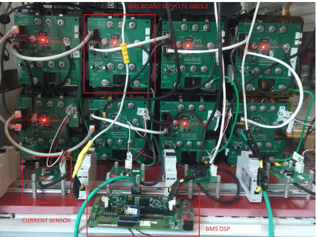
In order for all the boards to share the same SPI communication bus with a DSP, ISO7220A
and ISO7221A (Texas Instruments [24]), high speed digital isolators from TI, are used. They
provide an isolated communication interface for the LTC6803-2 ICs which are powered from
their respective batteries. Figure 2.7 shows the actual setup of BMS system with all the eight
batteries with their respective BMS boards and the DSP that controls all of them.
2.1.3 Communication and Application Development Platform
While the DSPs are powerful enough to handle all the power electronics related sensing and
control operations, a dedicated central controller is required to act as an external communication
other devices in the FREEDM System (described in Chapter 3), but also serves as a platform
for implementing native algorithms and applications for the DESD (described in Chapter 4).
We chose the Beagle Bone Black (Figure 2.12a), a low cost embedded Linux based single board
computer for this purpose. It is powered by the AM3358BZCZ100 processor from TI, based on
the ARM Cortex A8 architecture. It runs a Debian distribution of Linux out of the box. On
the hardware side, it features 512 MB of RAM, 4 GB of Flash and a 1 GHz clock.
Internal Communication between the BBB and DSPs
The BBB handles internal communication with the DSPs to issue them power commands
and poll system parameters at run time. It also communicates with the BMS DSP to fetch raw
values of sensed cell module voltages and current for each of the batteries. Several board level
embedded communication options such as Inter Integrated Circuit (I2C) [25], Serial Peripheral
Interface (SPI) [26], Controller Area Network (CAN) [27] and Modbus over Serial line [28, 29]
were evaluated to chose a suitable mechanism to handle this internal communication between
the BBB and DSPs. The most significant factors to consider in this context were:
1. The communication protocol should have minimal processing and computational
requirements as the DSPs could be running power control loops at frequencies in the
order of tens of kHz, which implies a system interrupt atleast every 100 µs. The digital
control loop’s execution time typically runs in tens of microseconds thereby leaving only
so much more time for the DSP to handle other housekeeping and communication tasks.
2. Since the communication between the BBB and DSPs shall be performed in an electrically
noisy environment as the power converter(s) would be operational, it should have
built-in defence mechanisms for error identification, else we run the risk of undetected data
corruption which could lead to unsafe operation.
3. It should be a modular and scalable mechanism as a single BBB would need to
future enhancements should be smooth.
4. Topolgy wise, it would essentially be a Master- Slave mechanism with the BBB as Master
and all the DSPs as slaves. So the BBB should have the flexibility to either broadcast it’s
commands to all the slave DSPs or individually address them if required.
5. The DSPs would be electrically isolated from each other as well as from the BBB as they all
could be powered from different sources. The underlying physical layer for communication
should support such a scheme.
SPI
We begin our evaluation with SPI, it being the simplest protocol amongst all possible
options.However it does not meet most of the above requirements. It’s not scalable (requires
a dedicated chip select pin CS for each slave), doesn’t have any inherent error checking,
cannot be used for broadcast communication and would lead to complicated wiring for isolated
Figure 2.8 Single SPI Master communicating with multiple Slaves over an isolated network. Note the need for a dedicatedCS signal for each Slave
I2C
I2C was originally designed for communication between an embedded controller and a peripheral
IC like memory chips or external ADCs. While it does support a well defined multi-slave
networking scheme, driving the bus for slaves that are physically not on the same board is
often challenging because the bus lines are passively driven with pull up resistors. External
Figure 2.9 Single I2C Master communicating with multiple Slaves over an isolated network. SDA (Data) line is bidirectional requiring sophisticated isolation provisioning
CAN
CAN bus has been designed to provide robust performance in noisy environments with features
such as differential bus signalling, multi-node communication, sophisticated mechanism for error
detection and fault handling and high speed communication throughput (a baud rate of up to
1 Mbps is possible). It makes for a viable choice but given it’s flexibility and features,it is
considerably more complicated to implement and troubleshoot. Moreover, as each board would
end up requiring an isolator and a CAN transceiver, it would lead to non-trivial wiring.
Modbus over Serial Line
Finally, we consider the Modbus over UART scheme. Modbus is an open standard protocol
quite popular in industrial control applications. It defines a Client-Server model where multiple
servers could be connected to the same Client, which maps perfectly with the desired
Mater-Slave scheme. It follows a query-response architecture that is supported by an acknowledgement
and a 16 bit Cyclic Redundancy Check (CRC) mechanism for fault identification. Modbus,
fundamentally being an application layer protocol in terms of the OSI model, is supported
by several physical layer options ranging from RS-232 to Ethernet. For typical embedded
microcontroller multi-slave applications Modbus is implemented over an RS-485 physical layer
bound by the UART channels of controllers, which could be isolated if required. We instead opt
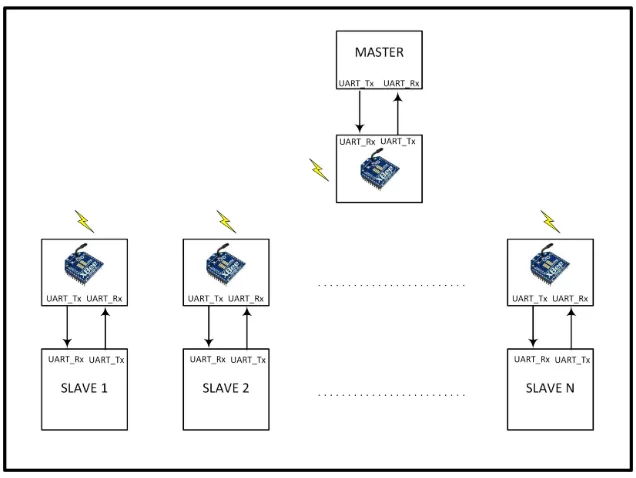
to use XBee radios with the controllers to greatly simplify isolation and assembly. XBee radios
are manufactured by Digi International and they communicate over an RF network based on
the IEEE 802.15.4 standard [30]. We use the XB24-AWI-001 modules [5] (Figure 2.12b) due to
their reasonable power consumption (50 mA) and easy to implement UART interface with the
controllers. So all the DSPs and the BBB have a XBee radio mounted to their respective UART
ports such that they form a multi-drop network .As far as the controllers are concerned, they
just work with their respective UART ports (where the XBee radios are interfaced) without
really bothering about the management of the wireless network, as that’s handled completely by
the XBee radios themselves. Using XBee radios also gets us around the grounding and isolation
Figure 2.11 Modbus Communication over Serial Line (UART) using XBee
In the current implementation for the DESD, not all the DSPs communicate with the
BBB over Modbus though. This is due to legacy reasons as the DSPs controlling power
electronics already had their communication interface defined previously. Thus only the BMS
DSP communicates with the BBB over Modbus. However, since the underlying physical layer
is still UART for either of the cases, its indeed possible to have proprietary and Modbus
implementations working on the same network with appropriate safeguards in place for
preventing misinterpretation of data. (Appendix A).
Implementation
Modbus needs to be implemented on both Master as well as Slave sides. While the master side
code runs on the Linux platform, the slave side code runs on the DSPs. Accordingly, dedicated
software meant for each of the platforms needs to be used.
We used theFreeModbus library [31] as the base code for the slave side. FreeModbus provides
(a) (b)
Figure 2.12 (a)Beagle Bone Black. Adapted from [4] and (b) XB24-AWI-001. Adapted from [5]
ports available for various platforms such as for controllers from Atmel, Freescale, TI etc.
However, it wasn’t ported for the DSP (TMS320F28335) used in the DESD. Therefore the
FreeModbus library was ported for the DSP being used in this project.
The software development on BBB can be done in a variety of languages such as C, C++,
Python etc. We chose Python and accordingly themodbus-tk package [32] for Python was used
to implement the Modbus Master routines. It’s an open source implementation of Modbus
master developed primarily by Luc Jean.
2.2
System Operation
The BBB board controls the operation of DESD by issuing appropriate commands to the
DSPs to actuate the hardware. As previously stated, this communication between the BBB
and DSPs is conducted using XBee radios over the wireless RF network. The XBee radios are
appropriately configured such that the one connected to the BBB acts as a Master and all the
Master - Slave modules is then handled in a command/query-response fashion.
At run time, the BBB is expected to receive a power dispatch command for the DESD from
an external device as a result of an intelligent power or energy management algorithm running
on that external device. Once the BBB receives this dispatch command, which could be either
a charge or discharge command, it formulates the corresponding data frames for each of the
DSPs (Appendix A) and transmits them via the XBee network.
The BBB also periodically polls the raw battery cell module voltage, current and temperature
(V,I,T) data from the BMS DSP and processes it at a sampling rate of 1 second to run the
SoC estimation algorithm. Further details about SoC estimation algorithm are provided in
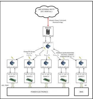
Section 4.2. As shown in Figure 2.13, we have a two tier controller system in place consisting of
the DSPs that directly control the hardware and the BBB board that acts as a communication
gateway for the DESD and also as a platform for developing native applications. This kind
of a layered architecture of controllers suits even a DRER or an SST kind of power converter
as they both need to perform communication and control operations just like the DESD. It is
noteworthy that the BBB neither directly interacts with the hardware nor handles any sensing
or control operation for the power electronics. This sort of decoupling leads to a modular design
as any of the sub components can be later changed or upgraded with minimal changes in rest of
the system. Not only that, the capability of the BBB to communicate with multiple slave DSPs
also makes the design reasonably scalable as additional DSPs can be added in any converter
Chapter 3
Communication Architecture for
DESD
The DESD is designed to work in conjunction with other smart power converters that form the
FREEDM Energy Cell so that it can play it’s role in acting as a reservoir of energy that’s charged
or discharged strategically. Considering this need for close coordination amongst the different
power converters within the Energy Cell, it’s essential that a standard communication interface
be designed to simplify system integration. We begin our analysis in Section 3.1 by investigating
the various possible architectural configurations for the DESD in the FREEDM System which
would allow us to identify the communication requirements for it. In Section 3.2 we perform
a comparative analysis of various standard protocols and their suitability for usage with the
DESD. Section 3.3 describes the implementation details of the communication architecture
arrived based on the issues identified so far and Section 3.4 discusses the performance results
3.1
DESD Architectural Configurations
A DESD could potentially be deployed at any level of hierarchy within the power distribution
network. Two representative cases could be :
1. Community Energy Storage Device: A community of end users which is served by an SST
type of Energy Router could be supported by one or more DESDs to deliver functionalities
such as peak shaving, load levelling, frequency regulation or voltage control. In such use
cases, the DESD is used as a captive energy source to mitigate intermittent fluctuations
in demand and supply of power thereby ensuring a smooth and reliable provision of ‘grid’
power to the end user. The SST shall be directly governing the operation of the DESD
based on the IEM algorithms running on it.
Figure 3.1 SSTs directly controls their respective DESDs as a means to match demand-supply constraints. The DGI software manages IEM algorithms on SST to control the power flow operation
2. Residential Energy Resource: The DESD could also be located closer to the end user
by serving a smart house or a smart building system directly. Here it is more likely to
be used in conjunction with a DRER based on solar or wind power. Typical use cases
generation by DRER or as a back up for uninterrupted power supply (UPS) schemes. The
DESD is essentially used to make economically optimal use of the grid power. In such a
case, the DESD could be controlled by a Home Energy Management System (HEMS) or
a Building Automation System (BAS). It is noteworthy that in such cases, the HEMS or
BAS could in turn be coordinating with an SST like device to negotiate the power flow
direction and quantum in real time.
Figure 3.2 DESD as a part of a smart home, controlled by an intelligent HEMS
Irrespective of the way a DESD is deployed, it needs to be intelligently controlled by an
external entity. We therefore need a reliable Machine to Machine (M2M) messaging mechanism
to interface with the DESD. Since the ethernet based TCP/IP network is pervasive and growing,
thanks to the Internet of Things (IoT) phenomenon, it’s but natural to look for a solution from
this domain to meet our communication needs. A BBB like single board computer serves this
functionality adequately as the underlying operating system provides the necessary resources
to deploy any such messaging infrastructure.
Another observation that one can make considering the above usage scenarios is that the
identify and interact with each other. The characteristics of this network would be data transfer
of small packet size but high frequency, low communication latency (for effective control) and
support for devices across the power/ performance spectrum: from wireless sensor networks and
embedded single board computers to sophisticated supervisory platforms and servers.
Based on the use cases described above and the operational details of the DESD within the
Energy Cell, we can identify the following requirements for the M2M messaging protocol:
1. To control the DESD, short but frequent data transfer is needed. Status information
(such as state of charge, residual energy capacity etc.) shall be frequently polled whereas
commands to start/stop or dispatch power flow (direction and quantity) would be
delivered to the DESD. So while the payload size would typically be only a few bytes, it
needs to be exchanged periodically (typically in the order of seconds). So the messaging
protocol should be efficient and have low overheads such that it can work even on low
bandwidth networks.
2. The DESD might also need to communicate it’s status information to a SCADA like
supervisory system. There could also be independent ‘observers’ on the network that
could be maintaining a database or logging usage statistics for any applications. In
such a scenario, the messaging protocol should have in place a mechanism to allow the
DESD to communicate it’s state to more than one entity on the network. However, since
such a supervisory mechanism could also be retrofitted as it does not directly affect the
functionality of the DESD, we would need the messaging protocol to handle the situation
with minimal changes on DESD’s end.
3. The chosen messaging protocol has to be application agnostic and scalable enough to
become the glueing logic for not just the DESD but also DRERs and other devices within
the Energy Cell. End users might also want to avail the real time status of their devices
be having resource constrained hardware as their communication gateway and hence the
messaging protocol has to feature a light weight implementation with minimal overheads.
4. Compliance with the IEC 61850 standard [33] is being actively pursued in substation
automation domain. It defines a hierarchical data model to map a device’s physical
attributes to the data points that the device can exchange with an external entity [34].
While devices such as the DESD do not necessarily fall within the scope of IEC 61850, it
would be prudent to chose a messaging protocol that would support hierarchical object
model so that compliance in future to similar or derived protocols is ensured.
3.2
Evaluation of M2M and IoT Messaging Protocols
Given the analysis presented in Section 3.1, we considered several M2M messaging protocols
to evaluate their suitability for our application.
HTTP
The Hypertext Transfer Protocol (HTTP) [35] was the first protocol to be considered as it has
been thede factostandard for information transfer over the Web. HTTP is designed to work on
a Client-Server model as a request-response protocol. At the simplest level, the client essentially
sends a request to the server to fetch or set data. It’s intended usage is for transferring sizeable
chunks of data over the World Wide Web. Such an architecture is not suitable for our application
as the underlying complexity and verbosity of HTTP would work against our design needs for
a light weight protocol. Moreover, the Client-Server model for point to point communications
doesn’t scale up well in a distributed environment where multiple nodes could be tracking the
CoAP
We next consider the Constrained Application Protocol (CoAP)[36], which is a simpler
alternative to HTTP. It is optimized for platforms with constrained power and processing
capabilities. It has a simplified header mechanism as compared to HTTP while still providing
mapping methods to HTTP via defined proxies. It also supports multicast communication with
resource discovery. However unlike HTTP which uses TCP, CoAP uses UDP to manage the
Transport Layer. This comes with it’s own drawbacks as retries and re-ordering need to be
implemented in the application stack. CoAP also provides options for ensuring reliability (two
qualities of service: ‘conformable’ and ‘nonconformable’)and resource discovery. We considered
CoAP to be a viable option while continuing to explore other alternatives.
AMQP
Advanced Message Queuing Protocol (AMQP) [37] is another application layer protocol
initially developed by the financial industry. It’s an enterprise level feature rich protocol designed
for message passing between servers. It follows a publish - subscribe (pub-sub) model for message
passing. In a pub-sub design, the sender does not transmit message to any specific recipient,
rather the message is published to a particular ‘topic’ which could be subscribed to by one
or more peers on the network. This requires the use of a ‘broker’ on the network to manage
message routing. Such an architecture is easy to scale as the message transmitter no longer
has to bother about intended recipients because that is completely managed by the broker.
Moreover, a topic based messaging mechanism easily renders itself to hierarchical messaging
as hierarchical topics can be formed which can then be selectively subscribed to by interested
recipients. AMQP is also quite comprehensive in the sense that it supports multiple messaging
patterns like round-robin, message queuing, store-and-forward etc. However, such a rich feature
set comes at the cost of communication overhead (the smallest packet size is 60 bytes) and
MQTT
We finally turn to MQTT (Message Queuing Telemetry Transport) which was originally
developed by IBM and recently (November 2014) was formalized as an open standard managed
by OASIS (Organization for the Advancement of Structured Information Standards). MQTT
provides a simple pub-sub model designed for resource constrained devices, typically embedded
systems. While it’s simple to implement, it still supports three qualities of service :
fire-and-forget(unreliable), atleast once (to ensure a message is sent a minimum of one time) and exactly
once. It also provides a hierarchical topic based message passing.
[38] provides a comprehensive overview of the underlying mechanism for working, reliability
and security of some of the protocols discussed above. Based on these observations with regard to
the various protocols considered, HTTP and AMQP were ruled out because of their processing
overheads and high data bandwidth requirements. They wouldn’t be a suitable choice for
transferring short but frequent messages across multiple nodes on a network. We eventually
narrowed down the choice between CoAP and MQTT.
According to [39] MQTT experiences lower delays than CoAP for lower packet loss and higher
delays than CoAP for higher packet loss. MQTT’s underlying layers being TCP as compared
to CoAP’s UDP leads to simpler application layer as message reordering need not be explicitly
handled. By providing a hierarchical topic based message transmission mechanism, MQTT can
be suitably adapted in future to support IEC 61850 like protocols, though it would involve a
fairly complex mapping from real world parameters to virtual data objects and eventually
to topics for the messaging layer. MQTT also gels perfectly well with an allied protocol
called MQTT-SN (MQTT for Sensor Networks) [40] which is a pub-sub protocol for Wireless
Sensor Networks. It can be thought of as a version of MQTT which is designed for wireless
communication environments. Such a provisioning could lead to easy integration, especially in
home over MQTT-SN and with other devices in the Energy Cell using MQTT. Considering
these issues, we selected MQTT for communications amongst the devices within an Energy
Cell.
3.3
Architecture and Implementation of the MQTT based
Communication Network
3.3.1 Architecture of the FREEDM MQTT Network Overview of the MQTT Protocol
MQTT is described as a pub-sub messaging protocol that uses TCP/IP under the hood. Any
given MQTT network consists of one or more clients and a single broker. All the clients on a
network communicate with each other via a broker. As such, all the clients are decoupled from
each other and are connected only to the broker. An MQTT client could be any device, varying
in computational power from a microcontroller to a server, that can run any implementation
of the MQTT library on it. The client could be a publisher, subscriber or both. Publishers tag
their messages with topics and transmit them to the broker. Subscribers let the broker know
about the message topics they are interested in. It’s the broker that receives all the messages,
filters them based on their respective topics and then forwards them to appropriate subscribers
for each message. A powerful implementation of broker can handle subscription of thousands of
clients. The broker is also responsible for handling authentication and security over the network.
[41] is the complete specification of the protocol and [42] provides a comprehensive overview
of the protocol from an implementation perspective. Moreover, one can also use TLS/SSL
(Transport Layer Security/ Secure Sockets Layer) protocol for encryption purposes if required.
MQTT also provides username/password based authentication mechanism for the clients to
Figure 3.3 Example of an MQTT Network using hierarchical topics to organize messages
As an example, consider a simple thermostat system for home that uses an MQTT network
as shown in Figure 3.3. Clients A, B , C and D are connected to a central broker, and are
agnostic about each other’s presence. Client A is a a temperature sensor that publishes the
real time temperature value to the network using the topic Home/Sensors/T emperature.
Client B is subscribed to it because it manages the cooling system and uses the temperature
sensor’s value for control purposes. Client B is also a publisher for the fan speed parameter
which being acquired by a sensor, is published under the topic Home/Sensors/F anSpeed.
Client C is basically a data logger and is therefore interested in all the sensor readings available
over the network. As such, it subscribes to the broker using a wild card topic using an ‘*’.
as Home/Sensors/∗. This basically tells the broker that Client C is interested in all the
data published under the topic of ’Sensors’. Client D being a remote display is interested
in only displaying the temperature data and therefore subscribes specifically to the topic
Home/Sensors/T emperature. This is makes the topic based pub-sub communication not only
MQTT Network in FREEDM Energy Cell
In the context of the FREEDM Energy Cell, we can think of all the possible devices within
the Energy Cell as MQTT clients which network via a broker as shown in Figure 3.1. The
broker, essentially being software driven, could be actually running on any of the client devices
as well to reduce the device count on the network. So a possible configuration could be that
all the DRERs, DESDs, FIDs etc. connected to a given SST can have an instance of MQTT
client running on them . Now since all of them need to communicate atleast with the SST, even
the SST shall have an instance of MQTT client running on it. Moreover, the broker could be
running from SST itself as a background process.
Another possible configuration for the Energy Cell could be as shown on the right hand side
of Figure 3.4 where an SST directly networks with a Smart Home in a small community. Here
we show an architecture that further exploits the choice of MQTT by having a tiered networking
structure. Internal to the home, all the smart sensors and appliances could be communicating to
the HEMS via MQTT-SN or MQTT as applicable. We assume the presence of an appropriate
Gateway device to couple the two networks. And then the HEMS as a single entity could
network with the SST to arrive at an optimal power usage operation.
Looking at a possible overall FREEDM communication architecture in Figure 3.4, the
communication across SSTs is handled using TCP/IP sockets as managed by DGI. The SSTs
could also need to communicate to a SCADA server or any central command centre. Since this
falls within the ambit of a distribution network, a protocol like DNP3 or IEC 61850 is ideal for
this purpose.
3.3.2 Implementation of the MQTT based Communication Network
We have used open source tools for our implementation of MQTT. The broker services
Figure 3.4 Multi-Tiered Network Architecture of the FREEDM System
implementation of Eclipse Paho project [44].
Device Profile
MQTT doesn’t specify any data model for messaging as a part of it’s standard. It’s completely
up to the application to specify the message format and it is assumed that the receiver is aware
of this message format. We devised a simple data model for prototyping purposes which can be
used by any of the small scale distributed entities within the Energy Cell.
We start with listing all the static and dynamic attributes of interest for the device in a
spreadsheet in a predefined format. This spreadsheet is called as the Device Profile of the
device. The device attributes could be either static (such as Device Name, Model, Version
etc.) or dynamic (Active Power , Temperature, Discharge Capacity etc.). Static attributes do
not influence the run-time behavior of the device whereas dynamic attributes either control or
report the run-time behavior of the device. Furthermore, the dynamic attributes could either
Figure 3.5 Device Profile of a DESD
or a command (IN) to the device by one of its peers in the network. Thus we come up with
further classification of device attributes as AIN, AOUT, DIN and DOUT. Static attributes
are correspondingly tagged by a field called DEV CHAR (device characteristics). Different
attributes belonging to the same tag are identified by their indices (starting with 0). The said
representation borrows heavily from the DNP3 representation of data points. This spreadsheet
also lists the default, minimum and maximum values for all the attributes which are used at
start up (for initialization) and run time (for boundary check). A sample device profile made
for the DESD is shown in Figure 3.5. The device profile is stored locally on the device’s BBB
or equivalent board.
Data Flow Mechanism
While the Device Profile provides an easy to manage interface for the programmer to add or
remove data points from the device’s object model, it is not used directly during run time as
working with spreadsheets at run time could be computationally intensive. Instead, we use a
data format called JSON (JavaScript Object Notation) to manage the data points at run time.
JSON defines a format for specifiying an order collection of name/value pairs which is light
weight (in terms of parsing) and easy to read/write (in terms of implementation as well as
time the MQTT client as well as any native applications on the device could read/write into
the data points. The JSON file then serves as a consistent means of storing the state of the
device across all the applications running on it. A set of API (Application Program Interface)
routines were developed to read/write specific data attributes from the JSON file with inbuilt
checks for atomic access (using file lock mechanisms), write protection and boundary checking.
Any application, including the MQTT Client, would be using these routines to access the data
Figure 3.6 describes the data flow path across devices and within their respective controllers.
For any given device (like for the SST and DESD shown), there could be multiple applications,
such as the MQTT Client, the Modbus implementation or any other native application (App)
that could be the producer or consumer of data points stored in the JSON file (device attributes).
While the Modbus code deals with translation and transfer of data points within the device,
MQTT Client handles the transfer of data points external to the device. As such, with regard to
the two-tier controller architecture described in Section 2.2, we can generically call the DSPs as
controllers for power electronics and BBB as an Application Platform (which could possibly be
any device with an operating system and a networking communication stack) for the purpose
of this discussion.
Consider the device communication between just the DESD and an SST for simplicity.To
begin with the DESD, at the simplest level, the DESD expects to receive commands for
start/stop, power dispatch etc. from the SST and the SST receives the residual energy left
in the DESD as a status update from it. All of these data points are listed in the Device Profile
for DESD. For example, start/stop being a binary value is considered a DIN because it is
received as an external Digital Input. Similarly, power command to the DESD is an AIN data
point (Analog Input) whereas the residual energy calculated by the DESD based on it’s BMS
system is quantified as an AOUT (Analog Output) data point. At the beginning of program
execution, the DESD’s application platform (BBB in our case) translates the Device Profile
(which is a spreadsheet) into an equivalent JSON format. This JSON file is also published over
the network so that the devices that are interested in controlling or monitoring the DESD can
do so based on the data points published therein. Any native application that wants to read
the AIN/DIN data points or write to AOUT/DOUT data points would be using the previously
mentioned API routines developed to handle the JSON file in order to do so. The Modbus
application would need to periodically poll for any updates in the data points that need to be
on the data received from the DSPs. The MQTT Client would be tracking any changes that
happen on the JSON file and if any of the AOUT/DOUT data points is updated by Modbus
or any other native application, then the MQTT Client shall push it over the network to the
broker with full hierarchy of the data point as the message topic. For example, if it wants to
publish the quantity of residual energy left in the DESD over the network, it would publish the
data point called ‘Discharge Capacity’ which is enumerated as an AOUT with index 0 in the
Device Profile, as a message with topic ‘DESD/1/AOUT/0’. The actual name of the quantity
is not required as a part of the message topic because the type (AOUT) and enumeration index
(0) are enough to uniquely identify the data point and it’s source.(DESD 1).
From the perspective of the application platform on SST, as soon as the DESD application
platform joins the MQTT network, it receives DESD’s Device Profile in the form of JSON file
because it would have subscribed for the same with the broker. The SST’s application platform
would also have another JSON file which it would have generated by itself based on it’s own
unique Device Profile. However, that JSON file is not relevant to the discussion here because
it plays no role in communicating with the DESD. As such, any device that controls another
device, shall have it’s JSON file in addition to it’s own JSON file. The MQTT Client on SST
has a two fold task: one, to subscribe to the relevant AOUT/DOUT topics of DESD so that
anything that the DESD publishes for those data points is received by the SST and second,
to publish to DESD’s AIN/DIN data points in order to control it. The static characteristics
of the DESD, under the category of DEV CHAR are not subscribed to because they are not
updated/published during run time, instead they are read directly from the JSON file received
at the beginning of the communication.
In this way, MQTT Clients on all the devices connected to the network essentially seek
to synchronize the data points for each device via updates in their respective JSON files.
Applications running natively on the devices can then read or write to the data points by
communication network.
Thanks to Siddhartha Kumar for developing the APIs to read/write JSON files concurrently
while using MQTT as the underlying communication network.
3.4
Performance Test of the Communication Network
We performed a set of tests to characterize the performance of our implementation of the
MQTT network and identify the critical factors affecting it. The various test scenarios, their
associated results and conclusions are as presented below.
All the hardware boards used during the tests were initially time synchronized to NCSU’s
NTP servers so that they can all be trusted to follow the same clock. Moreover, they are all
connected to NCSU’s ethernet network. Specifically, the Android phone and Ubuntu laptop are
connected via Wi-Fi whereas the BBB boards were connected physically to an ethernet switch
(TE-100 S8, Trendnet). the MQTT communication for all the tests was handled with QoS value
of 1, which ensures message delivery of ‘atleast once’.
3.4.1 Test A: Network of Two Devices
To model a communication network between just two devices, we used a variety of hardware
and software platforms as described in Figure 3.7. We performed tests to calculate the average
communication latency to transfer a data point from Client A to Client B. To represent analog
and digital data points, we performed the tests with message sizes of 10 bytes and 3 bytes
respectively. This is because, the minimum header size for MQTT is 2 bytes and therefore
considering an additional byte to represent digital data, the message size for it is 3 bytes. For
the analog data, the actual message size depends on the range and resolution of the number,
however, 10 bytes is considered representative of a typical data point.Table 3.4.1 lists the average
Table 3.1 Test Results for Communication Latency between two Clients representative of a DESD and an SST
Platform Test 1 Test 2 Test 3 Test 4
Client A
Intel Core i3-2370M 2.4 GHz Ubuntu LTS 14.04
Intel Core i3-2370M 2.4 GHz Ubuntu LTS 14.04
BBB ARMv7 Processor 300MHz
Debian 7.8
BBB ARMv7 Processor 300MHz
Debian 7.8
Broker
Qualcomm Snapdragon S4 Pro (ARMv7) @ 1.5GHz
Android v5.0 (Lollipop) MQTT Broker Pro
Intel Core i3-2370M 2.4 GHz Ubuntu LTS 14.04
Mosquitto Broker
Intel Core i3-2370M 2.4 GHz Ubuntu LTS 14.04
Mosquitto Broker
Qualcomm Snapdragon S4 Pro (ARMv7) @ 1.5GHz
Android v5.0 (Lollipop) MQTT Broker Pro
Client B
BBB ARMv7 Processor 300MHz
Debian 7.8
BBB ARMv7 Processor 300MHz
Debian 7.8
BBB ARMv7 Processor 300MHz
Debian 7.8
BBB ARMv7 Processor 300MHz
Debian 7.8 3 Bytes
(ms) 192.985 8.455 15.542 335.132
10 Bytes
Consider Test 1 that has a laptop powered by an Intel Core -i3 Processor and a BBB
communicating via a broker that is running on an Android mobile phone (LG Nexus 4). The
test results here are similar to Test 4 where the only difference is that the laptop is replaced by
another BBB device. This implies that the relatively high communication latency is not due to
the processing power constraints on the client platforms but rather due to the bottlenecks in the
broker’s performance. For Tests 2 and 3, we have lower communication latency as the broker
is actually running on the laptop which leads to superior performance. It should also be noted
that the broker implementations could also be considerably different since the one running on
laptops is the open source Mosquitto Broker whereas the one running on the Android device
is an ‘Android App’ called MQTT Broker Pro. Test 2 gives the lowest latency, as expected,
because one of the clients and the broker share the same powerful platform of the laptop. Test 3
reaffirms our observation that even with both the devices being BBB boards, the communication
latencies are low which implies that the performance of the broker holds the key to improving
network latencies.
3.4.2 Test B: Network of Three Devices
In this test, we added a ‘Listener’ device to the network. This ‘Listener’ device is
representative of any device that could be present on the network that wishes to snoop on
the data transactions occurring on the network in order to capture the states of the devices at
different time instances. Figure 3.8 shows the setup for the test case whereas Table 3.2 lists the
test results. For this test, the aim was to assess the impact on communication latency due to
Table 3.2 Test results for communication latency between three clients representative of a DESD, SST and a Data Concentrator
Client A
BBB ARMv7 Processor 300 MHz
Debian 7.8
Client B / Broker Intel Core i3 - 2370M
2.4 GHz Ubuntu LTS 14.04
Client C
BBB ARMv7 Processor 300 MHz
Debian 7.8
3 Bytes(ms) 5.777 8.876
![Figure 1.1 Electric grid with key elements of the FREEDM System. Adapted from [1]](https://thumb-us.123doks.com/thumbv2/123dok_us/1469070.1179994/16.612.136.494.290.537/figure-electric-grid-key-elements-freedm-adapted.webp)

![Figure 2.2 Topology of Cascaded H-Bridge DESD. Adapted from [2]](https://thumb-us.123doks.com/thumbv2/123dok_us/1469070.1179994/22.612.212.422.407.608/figure-topology-cascaded-h-bridge-desd-adapted.webp)
![Figure 2.3 Power Stage System Configuration of Cascaded H-Bridge DESD. Adapted from [2]](https://thumb-us.123doks.com/thumbv2/123dok_us/1469070.1179994/23.612.210.417.70.222/figure-power-stage-conguration-cascaded-bridge-desd-adapted.webp)

![Figure 2.12 (a)Beagle Bone Black. Adapted from [4] and (b) XB24-AWI-001. Adapted from [5]](https://thumb-us.123doks.com/thumbv2/123dok_us/1469070.1179994/34.612.109.522.69.289/figure-beagle-bone-black-adapted-xb-awi-adapted.webp)