Design and Implementation of Multilevel
Chopper using Bidirectional Control
Technique
R.Srinivasan1, D.Kalidass2, P.Iraianbu3
Assistant Professor, Department of EEE, Muthayammal College of Engineering, Rasipuram, Namakkal, Tamilnadu, India 1,2,3
ABSTRACT: In this paper we describe about the different cascaded multilevel topologies for utilizing the braking energy during regenerative braking with the help of super capacitor to dc bus in the regenerative applications. It is highly used in the high power application for the energy storage purpose. Super capacitors are chosen highly because of high density, efficiency and long life cycles. The modular multilevel dc/dc converter (MMC) is used to reduce voltage and increase frequency across the inductor in order to reduce the weight and size of the inductor with phase shifting modulation. It uses bi-directional power source and converter [2-5]. The super capacitors are used for voltage balancing for output current control. The proposed system is plays an important role in hybrid and electric vehicle applications.
KEYWORDS: Super capacitors, modular multilevelconverter, regenerative application
I.INTRODUCTION
Regenerative brake is an energy recovery mechanism during braking operation it slows a vehicle by converting kinetic energy into another form of energy, which can be used immediately or stored in energy storage system. This contrasts with the conventional braking mechanism, w here the excess energy is converted to heat by friction in the brake and wasted. Regenerative braking is one of the type electrical braking which is used in electric traction and hybrid in order to utilize the braking energy. During braking operation the energy dissipated in resistor or stored in different systems such as batteries, capacitors or super conductive magnets .Instead of that super capacitors or chosen for the simplicity and high power capability. Super capacitors are the energy storage devices they store energy in the form of electric field. Super capacitors are used as power sources, in front of batteries. So they are best placed in applications where high power levels are needed during a short period of time from milliseconds to few hundreds of seconds. Utility applications include uninterruptible power systems or utility voltage stabilizers in wind farms or photovoltaic (PV) plants.
In mobile applications, Super capacitors are connected with the batteries in order prevent from the damage during overvoltage condition; super capacitors will provide the balanced voltage and degraded the life of the battery and increase the efficiency of the system. It is also used to provide instant power whenever it is demanded. In these applications, SCs provide constant power and batteries’ constant energy. However, if the batteries are connected in parallel with the super capacitor directly it may cause m any drawbacks. The energy flow cannot be controlled in the parallel connection and also the voltage at which the capacitors are connected will be almost constant. Therefore the super capacitors are not used as energy source, but they are used as decoupling capacitor. In order to control the energy flow and achieve the energy management 1234 converter has been used [6-8].
Super capacitors are low voltage devices. Super capacitors are used in high power applications. To achieve Traction applications large number of cells is connected in series. The series connection of the cells may cause voltage imbalance in the system due to the capacitance difference in the each cell connection because of common series current. The voltage imbalance may cause destruction to the cell or premature failure of the super capacitor. On the other hand, instead of series connection we can use the parallel connection. But the parallel connection there is one disadvantage it requires some voltage adaptation [16-20]. The voltage adaptations are used in order to connect super capacitors to the high-voltage dc bus. Voltage adaptation can be achieved using bidirectional boost converter, but the inductor size will be high in needed. By using multichannel interleaved converters, the size of inductor can be reduced and efficiency can be increased if the discontinuous conduction mode is used. DC/DC bidirectional transformer isolated converters are also used [9-11].
In the HB converter the inductor is connected between two switches. The super capacitors are low voltage device. They are interfaced with the modular multilevel dc/dc converter in order to maintain the power constant. The super capacitors are used achieve high power with short period of time. The inductor size and weight will be reduced with the help of modular multilevel dc/dc converter and the power flow will be controlled. The converters are used to operate at low voltage level with high frequency with the inductor current ripple.
II. LITERATURE SURVEY
Literature Survey I:
Xiaofeng Sun, Member, IEEE, Baocheng Wang, Yue Zhou, Wei Wang, Huiyuan Du, and Zhigang Lu
ABSTRACT: In this paper, a novel cascaded seven-level inverter topology with a single input source integrating switched capacitor techniques is presented. Compared with the traditional cascade multilevel inverter (CMI), the proposed topology replaces all the separate dc sources with capacitors, leaving only one H-bridge cell with a real dc voltage source and only adds two charging switches. The capacitor charging circuit contains only power switches, so that the capacitor charging time is independent of the load. The capacitor voltage can be controlled at a desired level without complex voltage control algorithm and only use the most common carrier phase-shifted sinusoidal pulse width modulation (CPS-SPWM) strategy. The operation principle and the charging-discharging characteristic analysis are discussed in detail. A 1kW experimental prototype is built and tested to verify the feasibility and effectiveness of the proposed topology.
Literature Survey II:
M.Saravanakumar , C.Harris Naveen, Dr.M.Muruganandam, Muthayammal Engineering College, Rasipuram, Tamilnadu, India
is used to reduce voltage and increase frequency across the inductor in order to reduce the weight and size of the inductor with phase shifting modulation. The circuit is used as a bi-directional power source and converter. The super capacitors are used for voltage balancing for output current control. The proposed system is plays an important role in hybrid and electric vehicle applications.
III.CASCADED AND MMC
In the regenerative application the two quadrant dc/dc converter is used with battery. The battery is interfaced with the super capacitor during the breaking operation the energy will be flown to the battery through the super capacitor in order to maintain voltage balancing. Thus the converter is used to control the power flow and prevent from the damage. During traction mode the energy stored in the battery will be taken. It will be flown from the battery to the load. The super capacitors are used to maintain balancing condition during charging and discharging condition[11-12]. In the some system authors have described about the cascaded connection of flying capacitor and h bridge converter. In the proposed system we have used HB converter which is shown in the figure 1 with its current waveforms.
A.HB Converter
In the HB converter we have used two switches which is operated according to the required condition. In the buck mode the switch S1 will be operated where the output voltage will be less than the input voltage. In the boost mode the switch S2 will be operated where the output voltage will be greater the input voltage. Thus the voltage U1 and U2 is connected through the inductor L. The HB converter is bidirectional in current so the current control loop has been used. In the proposed system the voltage is irreversible, and the equation for the two voltages U1 and U2 is given in the equation 1. The equation for the two currents with respect to duty cycle is shown in the equation 2. The equations are given on the basis of the continuous conduction mode of operation.
U2=D· U1 (1) I1=D·I2 (2)
Where U1 and U2 are the voltage levels in each side connected in the converter with respect to the duty cycle limit given by 0 ≤D ≤1, thus I1 and I2 are the two currents of the converter the current waveform of the converter is shown in the fig1(b) there is a severe ripple at the voltage side U1[15-17]. The super capacitor of the dc bus can be connected voltage side either U1 or U2 in order to maintain the dc bus voltage constant. In the regenerative application the super capacitors are used to maintain voltage constant due to changes in the voltage. It is helpful in storing and releasing of the energy stored in the battery based on their requirement
When the super capacitors are connected to U1, the converter is said to work in the buck mode. During this mode, it reduces the output voltage which is lesser then the input voltage. When the voltage source U2 is connected, then the converter works in the boost mode where the output voltage will be greater the input voltage. Due to the constant operation the super capacitor is maintained at low current in order to increase the efficiency of the system. In order to maintain the stability SCs are operated between the rated voltages to half rated voltage.
IDC=I2=IL (3)
The equation for current through is given in the equation 3. During the boost mode the super capacitors will be fully charged at the initial condition which is equal to the dc bus voltage. When the energy stored in the super capacitor is discharged the voltage will be reduced to half of the rated dc bus voltage with the duty cycle of 0.5.
B. Cascaded Buck converter
sideU1. Where the SCs get fully charged at the condition Uscn = 2 Udc/N, where N is the number of the series connected modules.
C. Cascaded Boost converter
Thus the cascaded boost converter is connected with the series connection HB converter. In this mode the converter is connected at the high voltage side U1, when the super capacitors are connected at the low voltage side U2. Where the super capacitors are half charged at the condition Usc = Udc /2, with the duty cycle of 0.5 it has maximum ripple inductor current.
D. Modular Multilevel DC/DC converter
The modular multilevel DC/DC converter is shown in the figure 2(c). It is made through the series connection of HB converters. Due to the presence of the super capacitor and battery they are used in the high power application. The converter is operated unique due to the cascaded connection. If the converter is connected in series connection then it cannot be operated unique. Thus the modular multilevel dc/dc converter proposed in the paper, it depends on the each switching state of the HB converter with the phase shift modulation. Each HB has a Uscn = Usc/N voltage level.
Thus the frequency of the inductor is N times of the HB switching frequency Feq = N. FS, and the voltage
applied at the inductor is given as USCN. In the phase shift modulation triangular wave is used as carrier wave
compared with the reference wave of the output and makes the dc/dc converter to be operated with shift angle of 360./N with respect to the next HB converter cascaded.
E. SC Considerations: Input Filter
As said previously, SCs can be connected in the high voltage side U1 or in the low-voltage side U2. When connected to the low-voltage side U2, the inductor and SC current ripple is smaller compared with when connected to the high-voltage side U1. SCs cannot attenuate high-frequency currents. They behave as a resistor for frequencies above 100 Hz [28]. Therefore, when connected to the high-voltage side, filters must be installed [8]. LC filters are used because of low losses and simple design.
CBk and modular multilevel dc/dc converters need filters for SC current. Fig. 5 shows the LC filter used to filter input currents in SCs. An attenuation of approximately −30dB can be easily obtained with an Lf of 1% of the HB one-level converter inductor, and a filter capacitor C for a cut off frequency five times smaller than the switching frequency. When using filter in the SCs in the CBk and modular multilevel dc/dc converter, losses in SCs are reduced by a factor of D, but the inclusion of this filter can cause input disturbances to the controller.
IV. BLOCK DIAGRAM
During the breaking operation the energy will be flow from the load to source and energy is stored in the battery and the super capacitors are used in the voltage balancing. In order to control the fluctuations the converters are used by cascaded condition. The HB converters are used as buck and boost converter.
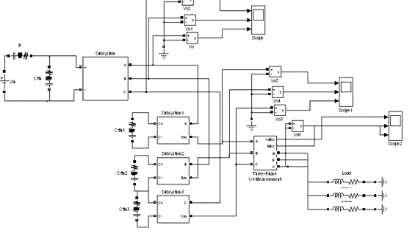
Fig. 2 Block Diagram of Modular Multi Level DC-DC Converter
In the boost mode the super capacitors are fully charged. In the proposed system four HB converters cascaded and connected to the single inductor r by using this condition the inductor size and weight of the inductor is reduced. Fuzzy logic controller is use d in the proposed system in order to increase the stability of the system. By using the super capacitor balanced voltage is given to energy storage system and used when it is needed. In order to equalize the energy store d in the super capacitor. The voltage at the super capacitor will be controlled at the same value with the help of converter.
V. SIMULATION AND HARDWARE CIRCUIT DESIGN
The simulation result for design and control of modular multilevel dc/dc converter for t he regenerative application is shown in the Fig 4. In the existing system they have used PI controller in the current control in order to increase the stability and efficiency of the system fuzzy controller is used in the current control loop. The HB converter has used two MOSFET for switching where the switch S1 will b e operated during the buck mode and the switch S2 will be operated during the boost mode. Likewise man y number of the HB converter is cascaded. The proposed model reduces the size and weight of the inductor by using phase shifting modulation.
SIMULATION RESULTS
Fig4 Output voltage and output current
A phase shifting modulation is used to allow the low voltage and high frequency to be applied across the inductor to reduce the size. The Super capacitors are used to maintain the voltage at the balancing in order to increase the life of the battery and prevent from the damage. Super capacitors are used for the high power applications. The energy stored in the battery are used whenever it is required
VI. CONCLUSION
The proposed system can b e used for both regenerative and the solar power applications. The main thesis of my project is to reduce the size and weight of the inductor by using the phase shifting modulation. The converter circuit is used to control the power flow and batteries are used to store the energy. The voltage balancing can be achieved with the help of the super capacitors in order to maintain the power constant at the battery. A phase shifting modulation of the modular multilevel dc/dc converter is used to operate for low voltage level with the high voltage applied across the inductor and to maintain the current ripple. The balancing loop used in the system help s to maintain the voltage balance during charging and discharging.
REFERENCES
[1]S.GubbeNamaratha ,S.Nalini “7 level modular multilevel dc/dc converter ,”IJES Trans jan 2014.
[2]M.Muruganandam, N.Senthil K umar, V.Sadasivam, ‘A Low-cost Four-quadrant Chopper-fed Embedded DC Drive Using Fuzzy Controller’, Published in Inter National Journal of Electric Power Components and Systems, Taylor and Francis, V olume 35, Issue 8 August 2007, pages 907-920.3.
[3]J.M.Miller“Propulsion system for Hybrid vehicle,”stevenage, U.K :Institution of engineering and technology,2010
[4]J.Dionisio Barros, J.Fernando, A.Silva and G.A.Jesus “Fast-Predictive optimal control of NPC Multilevel converters,” IEEE Trans vol60, no. 2, FEB 2013
[5]M.Muruganandam and M.Madheswaran, “Implementation of Hybrid Fuzzy- Neuro Controller for Chopper Fed PMDC Motor” 2nd International Conference on Computer, Electrical, Electronics & Mechanical Engineering (ICEEME'2013), organized by Planetary Scientific Research Centre, March 17-18, 2013, Dubai (UAE).
[7]J.M.Miller ,”Ultracapacitor application,” stevenage, U.K Institution of engineering and t echnology,2011 J.Dixion, S.Bosch, C.Castill o, and M.Mura “Ultracapacitors as unique energy storage for city-car using five level converter,” IEEE Ind Electron, 2009.
[8] M..Guan and Z.Xu ,”Modeling and control of a modular multilevel converter-based HVDC systems under unbalanced grid conditions,”IEEE Trans vol . 2, no.12 , DEC 2012.
[9]A.Rufer and P.Barrade,” A su percapacitors based energy storage system for the elevators with soft commutated interface,” IEEE Trans , vol.38 ,no.5 ,SEP-OCT 2002.
[10]M.Muruganandam and M.Madheswaran, Modeling and Simulation of Modified Fuzzy Logic Controller for Various types of DC motor Drives ” IEEE international conference on Control, Automation, Communication and Energy Conservation -2009, 4th-6th June 2009, Erode, Page(s):272 - 277 vol.1.
[11]C.Nagarajan and M.Madheswaran - ‘Experimental verification and stability state space analysis of CLL-T Series Parallel Resonant Converter’ - Journal of ELECTRICAL ENGINEERING, Vol.63 (6), pp.365-372, Dec.2012.
[12]C.Nagarajan and M.Madheswaran – ‘Analysis and Implementation of LLC-T Series Parallel Resonant Converter with Fuzzy controller’- International Journal of Engineering Science and Technology (IJEST), Applied Power Electronics and Intelligent Motion Control. Vol.2 (10), pp 35-43, December 2010
[13]C.Nagarajan and M.Madheswaran - ‘Performance Analysis of LCL-T Resonant Converter with Fuzzy/PID Using State Space Analysis’- Springer, Electrical Engineering, Vol.93 (3), pp.167-178, September 2011.
[14]C.Nagarajan and M.Madheswaran - ‘Stability Analysis of Series Parallel Resonant Converter with Fuzzy Logic Controller Using State Space Techniques’- Taylor & Francis, Electric Power Components and Systems, Vol.39 (8), pp.780-793, May 2011.
[15]C.Nagarajan and M.Madheswaran - ‘DSP Based Fuzzy Controller for Series Parallel Resonant converter’- Springer, Frontiers of Electrical and Electronic Engineering, Vol. 7(4), pp. 438-446, Dec.12.
[16]C.Nagarajan and M.Madheswaran - ‘Experimental Study and steady state stability analysis of CLL-T Series Parallel Resonant Converter with Fuzzy controller using State Space Analysis’- Iranian Journal of Electrical & Electronic Engineering, Vol.8 (3), pp.259-267, September 2012. [17]C.Nagarajan and M.Madheswaran, “Analysis and Simulation of LCL Series Resonant Full Bridge Converter Using PWM Technique with Load Independent Operation” has been presented in ICTES’08, a IEEE / IET International Conference organized by M.G.R.University, Chennai.Vol.no.1, pp.190-195, Dec.2007
[18]R.Raja and C.Nagarajan,“Performance Analysis of LCL-T Filter Based 2 Stage Single Phase Gird Connected Module with ANN Controller using PV Pane," Current Signal Transduction Therapy, Vol.13, No.2, pp.159-167,2018
[19]C. Nagarajan, M.Madheswaran and D.Ramasubramanian- ‘Development of DSP based Robust Control Method for General Resonant Converter Topologies using Transfer Function Model’- Acta Electrotechnica et Informatica Journal , Vol.13 (2), pp.18-31,April-June.2013
[20]M.Kannan, G.Neelakrishnan and R.Srinivasan “A Cascaded Multilevel H- Bridge Inverter for Electric Vehicles with Low Harmonic Distortion” in the International Journal of Scientific Engineering and Technology (IJSET) Nov. 2014.
[21]R.Srinivasan, M.Kannan and G.Neelakrishnan “AC/DC SEPIC Converter for Non-Linear Controller” in the IJAREEIE, Vol 3, Issue 11, Nov. 2014.
[22]R.Srinivasan et.al “A Hybrid Text Classification Approach Using Knn and Svm” in the International Journal of Advances Foundation and Research in Computer (IJAFRC), Volume 1, Issue 3, March 2014.
[23]R.Srinivasan and D.Vinoth have published a paper titled “Protection of Wireless Sensor Network from Gang Injection False Data Attack” in the IJAREEIE, Vol 3, Issue 2, and Feb. 2014.
[24]R.Srinivasan and D.Vinoth “Probabilistic Based Rock Texture Classification” in the International Journal of Advances in Engineering & Technology (IJAET), Volume 6 Issue 6, pp. 2439-2447, Jan. 2014.
[25]R.Srinivasan, D.Kalidass and D.Vinoth “Remote Admittance & Demonstrate for Client Control Mobile Computing” in the International Journal of Scientific Engineering and Technology (IJSET) Volume No.3, Issue No.1 pp: 13-16, Jan. 2014.
[26]R.Srinivasan and D.Vinoth “Characterization of Color and Texture Features from Retrieved Images using CBIR” in the International Journal of Research in Advent Technology (IJRAT), Volume 1, Issue 5, pp. 61-67 Dec. 2013.