Design & Selection of Automatic Lubrication
System For SPM
Gouri Prabhavalkar1, Sonal Gokhale2, Pournima Kamble3, Aishwarya Shinde4. M. S. Shinge5
U.G. Student, Department of Mechanical Engineering, BharatiVidyapeeth’s College of Engineering, Kolhapur, India1234.
Assistant Professor, Department of Mechanical Engineering, BharatiVidyapeeth’s College of Engineering, Kolhapur, India5.
ABSTRACT:This paper deals with the study and review of Automatic Lubrication System.Any rotating or sliding parts may develop certain amount of heat due to friction of the moving parts and consequently, there will be some wear and tear and loss of power. The most effective method of reducing friction to minimum and to save the metals from wear and tear is efficient lubrication and the substance used for this purpose is called lubricant. So proper lubrication system for lubrication is the most important arrangement for efficient running of engines and machine parts.
KEYWORDS:Automatic Lubrication, Lubricants, Design.
I. INTRODUCTION
Lubrication is the process or technique employed to reduce the friction between, and wear of one or both, surfaces in proximity and moving relative to each other, by interposing a substance called lubricant in between them t. The lubricant can be a solid, liquid or gas. Lubrication can be of two types 1) Manual lubrication and 2) Automatic lubrication. In earlier times only method to lubricate the parts was manual this leads to failure of lubrication due to excessive or less amount of lubricants. This results into low production, time consuming, sometimes the physical location on machine often makes it impractical to manually lubricate the points & it also requires maximum man efforts. Thus automatic lubrication system came into existence. In an automatic lubrication system, often referred to as pressurized lubrication system, is a system that delivers controlled amounts of lubricant to multiple location on a machine while the machine is operating.
Waghmare. S.L et al. [1] This project includes design and selecting of automatic lubrication system. Which allows to do oiling on regular time period and in adequate amount. This system also ensures safety to components and labour. It reduces manpower requirement for system lubrication. P.DivakaraRao et al. [2] In centralized lubrication system the goal is to reduce friction and dissipate some of the heat generated by friction. With centralized lubrication, every bearing receives the proper lubricant in an exact amount to minimize wear and promote longer service life Here different type of oil flow rate is wanted for the lubrication points these are all easily done with COL.T. Elakkiya and A. Anitta [3] Lubrication is the process or technique employed to reduce the wear of one or both surface in close proximity. Most of the bear lubrication fail due to the too much or too less grease injected using manual lubrication. So, to replace the manual lubrication discrete wiring employed in lubrication system in heavy machines using PLC.
pump,Meteringcartridges,Manifolds,Tubings and Fittings.With the help of these components we have designed the circuit layout of automatic lubrication system for this machine.
II. RELATED WORK
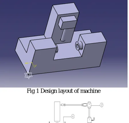
Fig 1 Design layout of machine
Fig 2 Flow Diagram For Automatic Lubrication System
This is two way drilling and one way reaming machine there are two spindles for drilling and one spindle for reaming. This machine is beneficial for work shop where drilling and reaming perform simultaneously on job. The motor used for drilling and reaming is of 3 HP three phase induction motor.
The job operated on this machine is a Valve Guide which is a cylindrical piece of metal, pressed or integrally cast into the cylinder head, with the valve reciprocating inside it. It is used in the cylinder head of the ships, it is the sleeve that valve moves up and down in and keeping it moving in an in and out motion.
With the help of machine layout, flow diagram for automatic lubrication system is designed. There are six lubricating points on this machine for which this system is designed.
Metering cartridges Manifolds
Tubings and fittings
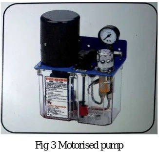
1.Motorised pump :
Fig 3 Motorised pump
Table no. 1 Specifications of Motorized pump CL2700Dx
Pump it is central source of oil in lubrication line. It is mini hydraulic power pack fitted with motor and rotory positive displacement pump.This unit fitted with pressure gauge,floatswitch,transperent reservoir.The unit is designed for intermittent run only and best suitable for single short centralized lubrication.
2.Metering cartridges : The element is a valve which ejects out metered amount of oil to lubrication point.It is a sort of mini cylinder with a special check valve where stroke of piston determines the dosage of oil.The complete design of metering injector does not allow it to leak at low as well as at high pressure of oil.The ejected oil will not return back to the injector due to in-built check valve.The metering injectors are supplied along with copper seal ring.
We have selected D2 size on the basis of required amount of oil in cc. For this we calculated required amount of oil by considering area of guide ways and oil film thickness
Specifictions of moving slide = L=350mm, W=300mm, H= 75mm Discharge of Pump 0.75 LPM
Reservoir Capacity 2.7 liters. Transparent (in polycarbonate material)
Motor 0.09 KW, 1500 rpm, Single Phase, 220 VAC
Relief Valve Pre set at 12 kg/sq.cm.
Pressure Switch 220 V (Max), 1 Amp (Max), With 1 NO + 1 NC contact, Preset at 10 kg/sq.cm.
Fig 4 Metering Cartridge
Table no. 2 specifications of metering cartridges
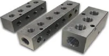
3.Manifold : Manifolds are nothing but steel blocks for mounting metering injector. These have two ports and few side outlets. On side outlets, metering injector are screwed directly while in lines ports are meant for joining next manifold.Manifolds are classified as one way(DM1),two way(DM2) upto ten way(DM10).We have selected DM-2 i.e two way for two injectors as there are two points on each side.
SIZE DOSE IN CC AREA (CM^2) Drops
D1 0.01 cc, 0.03 cc, 0.05 cc, 0.10 cc, 0.16 cc
Per Stroke.
Upto 4, 4to12, 12to20, 20to40,
40to65
1/3, 1, 2, 3, 5
D2 0.25 cc, 0.40 cc Per Stroke.
65to100, 100to150
8, 12
D3 1.00 cc, 1.60 Per Stroke.
150to400, 400to650
Table no. 3 specifications of manifold
4. Tubings and fittings :Tubing and fittings are basic accessories for the lubrication system.These are from the pump to the manifold and from the manifold to the lubrication point with in between metering cartridges tubing are required.For ejecting oil into the lubrication points, fittings are essential part of various threads.Tubings we have used are of 4 mm and 6 mm. 4 mm tube is used for metering cartridge and 6 mm tube is considered as a main pipe.Somefittings used for this system are as follows.
Straight Elbow Screws Tee-block Clamps Ferrule connector
Fig 6 Tubings and fittings Table no. 4 Fittings and their uses
Fittings Uses
Straight connector To connect 6 mm & 4 mm OD tube at the end point
Elbow For joining two tubes at right angle of 6 mm & 4 mm OD tube Screws For fixing clamps and to plug the manifold
Tee-block For dividing main line into three lines of 6 mm & 4 mm OD tube
Clamps For clamping tubes
Ferrule for fastening, joining, sealing or reinforcement.
L No of
Mounting
holes
W Thickness Port
III. ADVANTAGES AND DISADVANTAGES OF AUTOMATIC LUBRICATION SYSTEM 1) Advantages
Appropriate Oil Consumption
Variable Oil Dosages
Enhanced Machine Life
Elimination of Human Error
Increased Reliability
Increased Production
Low Noise Level
Less Power Consumption
Less Wear & Tear
SAFE, No Need to stop Machines
Reduced Spares/Inventory Costs
Overall Increased Profitability
2) Disadvantages
Expensive construction
Good sealing required
Supply of lubrication is made via centralized lubricating system (costly)
IV. EXPERIMENTAL RESULTS AND DISCUSSION
In order to achieve optimum reliability and maximum benefits from lubrication programme, several factors need to be taken into account. These factors are summarized by the wellknown five “R”s of lubrication:
The right lubricant
In the right quantity
At the right time
At the right point
With the right method
Once the five “R”s are defined, you can determine the best way to lubricate a component with the resources available.
V. CONCLUSION
REFERENCES
[1] Waghmare S.L. et.al., “Review of Automatic Lubrication System”, International Journal of Engineering Technology, Management and Applied Sciences ( Vol 3 Issue 3, ISSN 2349-4476)
[2] P. DivakaraRao. et.al., “Design of Centralized Oil Lubrication for Writing & Printing Paper Plant ”, ( Vol 3 Issue 1, 2013 )
[3] T. Elakkiya and A. Anitta , “ Comparative Study of Manual Lubrication and Automatic Lubrication ”,(ISSN : 2248-9622, Vol. 5, Issue 2, ( Part -4) February 2015, pp.16-20)
[4] Bruce L. Taia, ,David A. Stephenson, Richard J. Furness, Albert J. Shiha 'Minimum Quantity Lubrication (MQL) in Automotive Powertrain Machining', 6th CIRP International Conference on High Performance Cutting, HPC2014
[5] E.R. Booser and A.E. Baker (1976), "Evaporation-A Factor in Ball Bearing Grease Life," NLGI Spokesman, 40, P60-65. 3) T. Kawamura, M. Minami and M. Hirata (2001), "Grease Life Predication for Sealed Ball Bearings," Tribology Transactions, 44, 2, P256-262.
[6] Ito, H., Koizumi, H., and M. Naka. (1995), “Grease Life Equations for Sealed Ball Bearings,” Proceedings of the International Tribology Conference, Yokohama, Japan, pp 931-936.
[7] Scarlett, N.A. (1967), “Use of Grease in Rolling Bearings,” Proc. IMechE. Part 3A, 182, pp 167-171.
[8] H. Mikami: "Latest Trends in Lifespan Prediction for Lubrication Grease and Grease," Hydraulics & Pneumatics (Japan) 576, Vol.46, No.11, (2007) P42- 46.
[9] Bowden, F.P. Council for Scientific and Industrial Research, East Melbourne, Australia and Tabor, D on Mar 1947- The Lubrication by Thin Metallic Films and the Action of Bearing Metals.
[10] Mohawk College of Applied Arts and Technology: Reasons for Lube Systems; MATLLUB04. January 2007, FLO Components Ltd. [11] Lincoln Industrial Corporation: Quicklub Centralized & Automated Lubrication Systems. April 2007.
[12] Paul Conley, Lincoln Industrial Corporation and Raj Shah, Koehler Instrument Company: Ventmeter Aids Selection of Grease for Centralized Lubrication Systems. In: Machinery Lubrication Magazine. January 2004
[13] Steve Cartwright; LubriSource Inc. Product Guide - Centralized Lubrication Systems. In: Machinery Lubrication Magazine. July 2002 .
BIOGRAPHY
Gouri Prabhavalkar1
U.G. Student, Department of Mechanical Engineering,
BharatiVidyapeeth’s College of Engineering, Kolhapur, Maharashtra, India1
Sonal Gokhale2
U.G. Student Department of Mechanical Engineering,
BharatiVidyapeeth’s College of Engineering, Kolhapur, Maharashtra, India1
Pournima Kamble3
U.G. Student Department of Mechanical Engineering,
Aishwarya Shinde4
U.G. Student Department of Mechanical Engineering,
BharatiVidyapeeth’s College of Engineering, Kolhapur, Maharashtra, India1
M. S. Shinge5
Assistant Professor, Department of Mechanical Engineering,