ISSN(Online): 2319-8753 ISSN (Print): 2347-6710
I
nternational
J
ournal of
I
nnovative
R
esearch in
S
cience,
E
ngineering and
T
echnology
(An ISO 3297: 2007 Certified Organization) Website: www.ijirset.com
Vol. 6, Issue 8, August 2017
Static and Dynamic Analysis of A Car Chassis
Using FEA
Katamaraju Ediga Madhu Latha1, Sri P Hari Shankar2
PG Student, Department of Mechanical Engineering, G.P.R College of Engineering, Andhra Pradesh, India1
Assoc. Professor, Department of Mechanical Engineering, G.P.R College of Engineering, Andhra Pradesh, India2
ABSTRACT: Car chassis typically refers to the lower body of the vehicle including the tires, motor, outline, driveline and suspension. Out of these, the frame gives essential help to the vehicle components set on it. Likewise the chassis ought to be sufficiently solid to withstand shock, twist, vibrations and different loads. The chassis outline comprises of side individuals appended with a progression of cross individuals. Alongside the quality an imperative thought in the suspension configuration is to increase the stiffness(bending and torsion) characteristics. Normally torsional stiffness is required to have great dealing with characteristics. Typically the chassis are composed on the basis of strength and stiffness. In the regular outline strategy the design depends on the strength and accentuation (emphasis) is then given to enhance the strength of the chassis. Structural system like the chassis can be effortlessly analyzed for the stress, and stiffness, and so on utilizing finite element analysis. The chassis is demonstrated in PRO-E software. Analysis is done on the demonstrated chassis utilizing the Ansys workbench.
KEYWORDS: Design, Analysis, Vibration,Natural Frequency,Car Chassis
I. INTRODUCTION
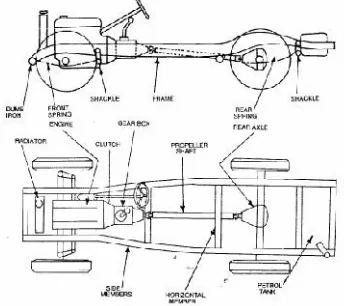
A body comprises of an inner structure that backings a man-made object in its development and utilize. It is comparable to a creature's skeleton. A case of a chassis is the under piece of an engine vehicle, comprising of the frame on which the body is mounted. If the running gear, for example, wheels, and once in a while even the driver's seat, are incorporated then the get together is depicted as a moving body.Chassis is a French term and was initially used to denote the frame parts or Basic Structure of the vehicle. It is the back bone of the vehicle. A vehicle without body is called Chassis. The components of the vehicle like Power plant, Transmission System, Axles, Wheels and tires, Suspension, Controlling Systems like Braking, Steering etc., and also electrical system parts are mounted on the Chassis frame. It is the main mounting for all the components including the body. So it is also called as Carrying Unit.
ISSN(Online): 2319-8753 ISSN (Print): 2347-6710
I
nternational
J
ournal of
I
nnovative
R
esearch in
S
cience,
E
ngineering and
T
echnology
(An ISO 3297: 2007 Certified Organization) Website: www.ijirset.com
Vol. 6, Issue 8, August 2017
II. LITERATURE SURVEY
RoslanAbdRahman has done stress analysis on heavy duty truck chassis by finite element package ABAQUS. To improve the fatigue life of components at critical point by design modifications the stresses can be reduces. He uses ASTM low alloy steel a 710 C (Class 3) with 552 MPa of yield strength and 620 MPa of tensile strength for chassis founds the maximum stress 386.9 MPa at critical point occurred at opening of chassis. This critical point is located at element 86104 and node 16045, which was in contacted with the bolt from it he concludes, that this critical point is an initial to probable failure.
MohdAzizi Muhammad Nordetermine the stress analysis of an actual low loader structure having I-beams design application of 35 ton trailer. He uses CATIA V5R18 for modeling. Analysis results show that the location of maximum deflection and maximum stress agrees with theoretical maximum location of simple beam under uniform loading distribution. This shows that there is discrepancy between the theoretical (2-D) and numerical (3-D FEA) results. It shows that the maximum deflection is pointed in situated in between BC1 and BC2 with magnitude of 7.79mm. The results show the numerical analysis revealed that the location of maximum deflection and maximum stress agrees well with theoretical maximum location of simple beam loaded by uniform force.
CicekKaraogluhas done stress analysis of heavy duty truck chassis with riveted joints by using a finite element package ANSYS version 5.3. He examine the effect of the side member thickness and connection plate thickness with length change, the thickness of the side member is varied from 8 to 12 mm, and the thickness of the connection plate is also varied by local plate from 8 to 12 mm, the connection plate thickness is varied from 7 to 10 mm, and the length of the connection plate (L) is varied from 390 to 430 mm during his study. From it he concluded that if it is not possible to change the side member thickness using local plates, because of increase in weight of chassis then choosing an optimum connection plate length (L) seems to be best practical solutions for decreasing the stress values.
Swami K.I. et al.(Jan. 2014)The Automotive chassis is considered as the backbone of the vehicle. On chassis, different parts are provided with strength, an important consideration in chassis design is to have adequate bending stiffness for better handling characteristics. So, strength and stiffness are two important criteria for the design of the chassis. This paper related with work performed towards the static structural analysis of the truck chassis. Structural systems like the chassis can be easily analysed using the finite element techniques. So a proper finite element model of the chassis is to be developed. The chassis is modelled in ANSYS. Analysis is done using the same software.
Kenji KARITA, Yoichiro KOHIYAMA, Toshihiko KOBIKI, Kiyoshi OOSHIMA, Mamoru HASHIMOTO (2003) had developed a chassis made by Aluminium. The material selected for the frame is 6061-T6. They used the Variable section extrusion method for making the chassis. It’s developed with the help of computer Aided Engineering. Aluminium material gives an advantage of weight reduction. From this study authors found that the Aluminium chassis meets the target of weight reduction, strength and rigidity. Also they concluded that the remaining technical issues will be addressed to enable commercial adoption of the aluminum frame.
Alireza Arab Solghar, ZeinabArsalanloo (2013) studied and analyzed the chassis of Hyundai Cruz Minibus. ABAQUS Software was used for modeling and simulation. Self-weight of the chassis is considered for static analysis and Acceleration, Braking and Road Roughness were considered for dynamic analysis. It’s observed that the stresses on chassis caused by braking were more compared with acceleration.
III. PRO-E DESIGN
Initially 2D drawings were created using sketcher toolbar; tools in profile tool bar such As line, rectangle, points, reference lines etc. and sketch references like grid, vertex, and dimensions are used.
ISSN(Online): 2319-8753 ISSN (Print): 2347-6710
I
nternational
J
ournal of
I
nnovative
R
esearch in
S
cience,
E
ngineering and
T
echnology
(An ISO 3297: 2007 Certified Organization) Website: www.ijirset.com
Vol. 6, Issue 8, August 2017
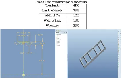
Table 3.1: the main dimension of car chassis
Total length 4130
Length of chassis 3988
Width of Car 1620
Width of track 1380
Wheelbase 2450
Fig 3.1 Sketcher of chassis Fig 3.2: Solid model of chassis
IV. ANALYSIS OF CHASSIS
ANSYS means Analysis System Product. Dr. John Swanson founded ANSYS. Inc. in 1970 with a vision to
commercialize the concept of computer simulated engineering, establishing himself as one of the pioneers of Finite Element Analysis (FEA). ANSYS Inc. supports the ongoing development of innovative technology and delivers flexible, enterprise wide engineering systems that enable companies to solve the full range of analysis problem, maximizing their existing investments in software and hardware. ANSYS Inc. continues its role as a technical innovator. It also supports a process-centric approach to design and manufacturing, allowing the users to avoid expensive and time-consuming “built and break” cycles. ANSYS analysis and simulation tools give customers ease-of-use, data compatibility, multi-platform support and coupled field multi-physics capabilities.
Static analysis is used to determine the displacements, stresses, strains and forces in structures or components due to loads that do not induce significant inertia and damping effects. Steady loading in response conditions are assumed. The kinds of loading that can be applied in a static analysis include externally applied forces and pressures, steady state inertial forces such as gravity or rotational velocity imposed (non-zero) displacements, temperatures (for thermal strain).
A static analysis can be either linear or nonlinear. In our present work we consider linear static analysis. The procedure for static analysis consists of these main steps:
ISSN(Online): 2319-8753 ISSN (Print): 2347-6710
I
nternational
J
ournal of
I
nnovative
R
esearch in
S
cience,
E
ngineering and
T
echnology
(An ISO 3297: 2007 Certified Organization) Website: www.ijirset.com
Vol. 6, Issue 8, August 2017
A. Material: Structural Steel st37
Static Analysis
Table 4.1 Properties of structural steel st37
Density 7850 kg m^-3
Coefficient of Thermal
Expansion
1.2e-005 C^-1
Specific Heat 434 J kg^-1 C^-1
Resistivity 1.7e-007 oh m
Young Modulus 2.1e+011 Pa
Poison’s Ratio 0.3
Fig 4.1Meshed Model Fig 4.2 applied boundary conditions
ISSN(Online): 2319-8753 ISSN (Print): 2347-6710
I
nternational
J
ournal of
I
nnovative
R
esearch in
S
cience,
E
ngineering and
T
echnology
(An ISO 3297: 2007 Certified Organization) Website: www.ijirset.com
Vol. 6, Issue 8, August 2017
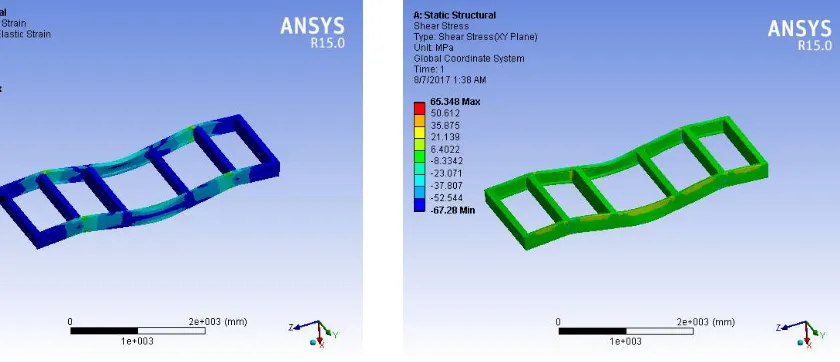
Fig 4.5 Equivalent Elastic Strain Fig 4.6Shear Stress
DYNAMIC ANALYSIS
Model Analysis
ISSN(Online): 2319-8753 ISSN (Print): 2347-6710
I
nternational
J
ournal of
I
nnovative
R
esearch in
S
cience,
E
ngineering and
T
echnology
(An ISO 3297: 2007 Certified Organization) Website: www.ijirset.com
Vol. 6, Issue 8, August 2017
Fig 4.9 Deformation of 1st mode shape Fig 4.10 Deformation of 2nd mode shape
ISSN(Online): 2319-8753 ISSN (Print): 2347-6710
I
nternational
J
ournal of
I
nnovative
R
esearch in
S
cience,
E
ngineering and
T
echnology
(An ISO 3297: 2007 Certified Organization) Website: www.ijirset.com
Vol. 6, Issue 8, August 2017
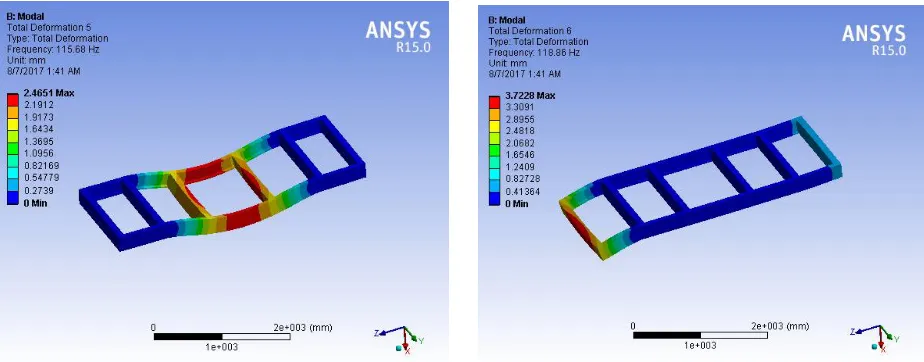
Fig 4.13 Deformation of 5th mode shape Fig 4.14 Deformation of 6th mode shape
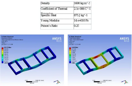
B. Material: Carbon epoxy fiber
Static Analysis:
Table 4.2 Mechanical properties of material
Density 1600 kg m^-3
Coefficient of Thermal
Expansion
2.1e-006 C^-1
Specific Heat 875 J kg^-1
C^-1
Young Modulus 14 e+010 Pa
Poison’s Ratio 0.25
ISSN(Online): 2319-8753 ISSN (Print): 2347-6710
I
nternational
J
ournal of
I
nnovative
R
esearch in
S
cience,
E
ngineering and
T
echnology
(An ISO 3297: 2007 Certified Organization) Website: www.ijirset.com
Vol. 6, Issue 8, August 2017
Fig 4.17 Equivalent Elastic Strain Fig 4.18Shear Stress
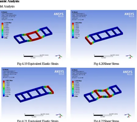
Dynamic Analysis:
Model Analysis
Fig 4.19 Equivalent Elastic Strain Fig 4.20Shear Stress
ISSN(Online): 2319-8753 ISSN (Print): 2347-6710
I
nternational
J
ournal of
I
nnovative
R
esearch in
S
cience,
E
ngineering and
T
echnology
(An ISO 3297: 2007 Certified Organization) Website: www.ijirset.com
Vol. 6, Issue 8, August 2017
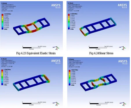
Fig 4.23 Equivalent Elastic Strain Fig 4.24Shear Stress
Fig 4.25 Equivalent Elastic Strain Fig 4.26Shear Stress
V. RESULTS AND DISCUSSIONS
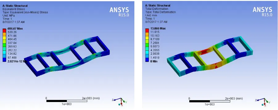
Table 5.1 static results
Properties St 37 Carbon
fibre Epoxy
Stress (MPa) 606.67 612.73
Shear Stress (MPa)
65.34 62.73
Strain 0.0106 0.00382
Displacements (mm)
ISSN(Online): 2319-8753 ISSN (Print): 2347-6710
I
nternational
J
ournal of
I
nnovative
R
esearch in
S
cience,
E
ngineering and
T
echnology
(An ISO 3297: 2007 Certified Organization) Website: www.ijirset.com
Vol. 6, Issue 8, August 2017
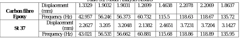
Table 5.2 Model Analysis Results
Carbon fibre Epoxy
Displacement (mm)
1.3329 1.9032 1.9031 1.2699 1.4638 2.2078 2.2069 1.8637
Frequency (Hz) 42.957 56.246 56.373 60.732 115.5 118.63 118.67 135.72
St 37
Displacement
(mm) 2.2627 3.205 3.2048 2.1382 2.4651 3.7231 3.7204 3.1427
Frequency (Hz) 43.021 56.535 56.662 60.881 115.68 118.86 118.89 135.95
VI. CONCLUSION
Generally, the material that is used in the construction of chassis is steel. But now the bigger automobile companies like BMW, Mercedes-Benz etc have already started using carbon fiber material. So we tried to compare the two materials i.e. steel st37 and Carbon fiber epoxy and through ANSYS and MATLAB found out the results that which material can withstand the loads applied and have less deformation. So below is the comparison theoretically and analytically.
When we compare density, then steel is denser than carbon fiber, steel density is about 7.9 kg/mm3 and carbon fiber density is 1.6 kg/mm3. Therefore carbon is much lighter and young’s modulus for steel is around 210000 MPa and whereas for carbon fiber it is 140000 MPa. We know that young’s modulus measures the resistance of a material to elastic (recoverable) deformation under load. So the material with high young’s modulus changes its shape slightly under elastic loading. Poisson’s ratio for steel is 0.33 and whereas for carbon fiber it is 0.25. The ratio of lateral strain by longitudinal strain is Poisson’s ratio. So material with less Poisson’s ratio has less deformation.
From Static Analysis of chassis, we found that Carbon Fiber have less shear stress, strain and deformation when compare to steel. But both materials values are under the allowable parameter so both withstand the loading conditions.
After calculating the Modal Analysis for both Materials we can conclude the mode shapes of chassis while in
motion. Where the different mode shapes according to the frequency are obtained.
After model analysis all deformations according to their frequencies are tabulated in table 5.7, 5.8, 5.11 and
5.12. Where we found carbon fibre epoxy have better performance than st37.
After MATLAB Simulink Simulation the maximum deformation variable is 5.5868 mm.
REFERENCES
[1] Stress analysis of a truck chassis with riveted joints by CicekKaraoglu*, N. SefaKuralay,
2002.Department of Mechanical Engineering, DEU Faculty of Engineering, 35100 Bornova,Izmir, Turkey ,Finite Elements in Analysis and Design 38 115–1130
[2] The effect of connection plat thickness on stress of truck chassis with riveted and welded joint under dynamic loads is carried out by M. zehsaz, VakiliTahami and Esmaeili. Asian Journal of applied Science 2(1): 22-35, ISSN 1996-3343.
[3] Dynamic Analysis of a Modified Truck Chassis by Mohammad Reza Forouzan., Majlesi Journal of Mechanical Engineering Vol. 3/ No. 4/ Summer
[4] Analysis of Torsional Stiffness and design improvement study of a Kit Car Chassis Prototype, by Wesley Linton, M.Sc. thesis,Cranfield University, School Of Industrial And Manufacturing Science Motor sport Engineering And Management
[5 Fermer, M., McInally, G., Sandin, G., “Fatigue Life Analysis of Volvo S80 Bi-fuel”, Proceedings of 1st MSC worldwide automotive conference, MSC, 1999
[6] Johansson, I., and Gustavsson, M., “FE-based Vehicle Analysis of Heavy Trucks Part I” Proceedings of 2nd MSC worldwide automotive conference, MSC, 2000
ISSN(Online): 2319-8753 ISSN (Print): 2347-6710
I
nternational
J
ournal of
I
nnovative
R
esearch in
S
cience,
E
ngineering and
T
echnology
(An ISO 3297: 2007 Certified Organization) Website: www.ijirset.com
Vol. 6, Issue 8, August 2017
[8] Parnell, T., White, C., and Day, S., “Finite Element Simulation of 180o Rollover for Heavy Truck Vehicles”, ASCE Engineering mechanics conference, Baltimore, 1999.
[9] Jin-yi-min, “Analysis and Evaluation of Minivan Body Structure” ,Proceedings of 2nd MSC worldwide automotive conference, MSC, 2000..