Volume 2007, Article ID 32807,9pages doi:10.1155/2007/32807
Research Article
Direct Conversion EHM Transceivers Design for
Millimeter-Wave Wireless Applications
Abbas Mohammadi,1Farnaz Shayegh,2Abdolali Abdipour,1and Rashid Mirzavand1
1Microwave and Wireless Communication Research Labratory, Electrical Engineering Department, Amirkabir University of Technology (Polytechnic), Tehran 1587-4413, Iran
2Electrical and Computer Engineering Department, Concordia University, Montreal, QC, Canada H4G2W1
Received 29 March 2006; Revised 14 November 2006; Accepted 15 November 2006
Recommended by Kiyoshi Hamaguchi
A direct conversion modulator-demodulator with even harmonic mixers for fixed wireless applications is presented. The circuits consist of even harmonic mixers (EHMs) realized with antiparallel diode pairs (APDPs). A communication link is set up to exam-ine the overall performance of proposed modulator-demodulator. The transmission of 16-QAM signal with 110 Mbps data rate over fixed wireless link has been examined. We also evaluate the different levels of I/Q imbalances and DC offsets and use signal space concepts to analyze the bit error rate (BER) of the proposed transceiver usingM-ary QAM schemes. The results show that this structure can be efficiently used for fixed wireless applications in Ka band.
Copyright © 2007 Abbas Mohammadi et al. This is an open access article distributed under the Creative Commons Attribution License, which permits unrestricted use, distribution, and reproduction in any medium, provided the original work is properly cited.
1. INTRODUCTION
Local multipoint distribution system (LMDS) is a broadband wireless point-to-multipoint communication system oper-ating above 20 GHz and provide high-data-rate voice, TV, and internet services. It is desirable to increase the spec-tral efficiency or the transmission capacity of LMDS ser-vices by using sophisticated amplitude and phase modula-tion techniques (QPSK and QAM). The cost reducmodula-tion in LMDS transceiver design is a key issue to increase the deploy-ment of this system. Among various realization techniques, the direct conversion implementation reduces the size and cost of LMDS transceiver. A direct conversion modulator-demodulator using even harmonic mixers (EHMs) is de-signed at 28 GHz for LMDS applications. The EHM is based on antiparallel diode pair (APDP). The APDP has a balanced structure that suppresses the fundamental mixing products (m fLO±n fIFwherem+n=even). These products flow only
within the APDP loop [1]. The EHM with APDP has some advantages that make it very attractive for millimeter-wave transceivers. These advantages are: (1) it can operate with halved LO frequency; (2) in direct conversion transmitter, it can suppress the virtual LO leakage (2fLO) that locates nearby
a desired RF signal; (3) it suppresses DC offset in direct con-version receivers.
The paper is organized as follows: the even harmonic mixer structure and three methods to improve its behavior are introduced. Then, a direct conversion modulator is de-signed using even harmonic mixers. The modulator struc-ture is reciprocal and can also be used as a direct conversion demodulator. Next, we consider the effects of I/Q imbalances and DC offsets on the bit-error-rate performance of the de-modulator for M-ary QAM schemes. Finally, a communi-cations link using direct 16-QAM modulator-demodulator with 110 Mbps data rate is successfully demonstrated.
2. EVEN HARMONIC MIXER
Figure 1(a) shows a circuit configuration of the even
Open-circuited stub
IF port RF port
LPF A
B LO port
BPF
Antiparallel diode pairs
Short-circuited stub
(a)
(b)
Figure1: (a) Circuit configuration of the even harmonic mixer, (b) Schottky diode nonlinear model.
−28.674, so there is a good matching in filter input and out-put. The GaAs Schottky barrier APDP (agilent HSCH-9551) is used to realize the mixer.Table 1shows its parameters.
This mixer is used to mix the baseband signal (at 100 MHz) with the second harmonic of the LO signal (at 13.95 GHz) to provide the RF signal at 28 GHz. Figure 3 shows the mixer conversion gain versus LO power [3]. This results are obtained from the harmonic-balance simulation.
Figure 1(b)shows the Schottky diode nonlinear model. In
continue, we introduce three ways to improve the mixer be-havior and reduce its conversion loss.
2.1. Matching networks
In this section, matching networks in both sides of the APDP are included in an effort to reduce the mixer conversion loss and the LO power required for optimal mixer conver-sion loss [4]. LO matching network consists of a series delay line followed by a shunt short-circuited stub. RF matching network consists of a series delay line followed by a shunt open-circuited stub. These matching networks are designed to match the APDP impedance at the LO and RF ports to 50 ohm. The length of these stubs is iteratively tuned to
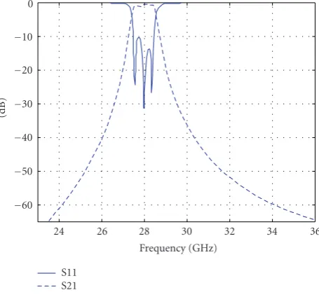
−60 −50 −40 −30 −20 −10 0
(dB)
24 26 28 30 32 34 36
Frequency (GHz) S11
S21
Figure2: Filters S11 and S12 (dB).
Table1: Diode parameters.
Junction capacitance (Cj0) 0.04 pF Series resistance (Rs) 6Ω Saturation current (Is) 1.6E-13A
Ideality factor (N) 1.2
provide good conversion loss at a relatively low LO drive level. Figure 4 shows the mixer conversion gain versus LO power with and without the matching networks. As we can see from this figure, matching networks result in decrease of LO power required for optimal mixer conversion loss and a slight improvement in mixer conversion loss.
2.2. Parallel diodes
As we know, series resistance (Rs) of Schottky diodes is a major factor in diode mixer conversion loss. If two parallel Schottky diodes are substituted for each diode in APDP, ef-fective Rs of the structure will be divided by an approximate factor of two and the conversion loss will be decreased [5]. Also use of three diodes instead of each diode causes more decrease in mixer conversion loss. For each of the above cases, matching networks should be designed again.
Figure 5shows the mixer conversion loss with one, two, and three diodes.
2.3. Self-biased APDP
−35 −30 −25 −20 −15 −10 −5
Con
ver
si
on
ga
in
(d
B
)
0 5 10 15 20 25 30
Oscillator power (dBm) Figure3: Conversion gain of the EHM.
−35 −30 −25 −20 −15 −10 −5
Con
ver
si
on
ga
in
(d
B
)
0 5 10 15 20 25 30
Oscillator power (dBm) Without matching networks With matching networks
Figure4: Mixer conversion gain.
APDP. The conversion loss of EHM using self-biased APDP is almost constant from 10 dBm to 25 dBm of LO power.
2.3.1. Numerical results
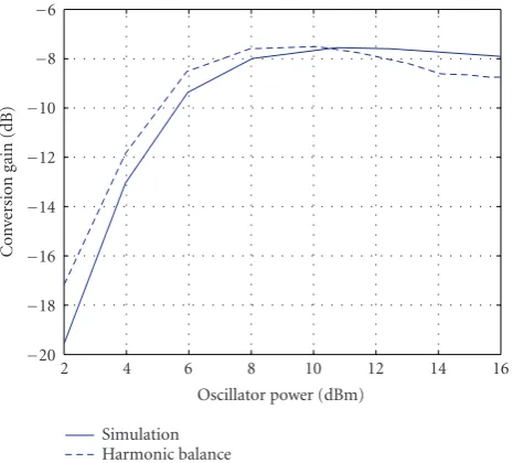
We also write a program with Matlab software in order to calculate the conversion loss of the EHM using self-biased APDP by the harmonic-balance method. Diode parameters used for calculation are obtained from the agilent HSCH-9551 data sheet. We set the RF frequency to 28 GHz and the RF power to−75 dBm. The RF signal is mixed with second harmonic of the LO signal.Figure 7shows calculated
conver-−13 −12 −11 −10 −9 −8 −7 −6 −5
Con
ver
si
on
ga
in
(d
B
)
0 5 10 15 20
Oscillator power (dBm) With 1 diode
With 2 diodes With 3 diodes
Figure5: Mixer conversion gain.
−35 −30 −25 −20 −15 −10 −5
Con
ver
si
on
ga
in
(d
B
)
0 5 10 15 20 25 30
Oscillator power (dBm) Self-biased APDP
Conventional APDP
Figure6: Conversion gain of the EHM using self-biased APDP and conventional APDP.
−20
Figure7: Conversion gain of the EHM using self-biased APDP cal-culated by the harmonic balance method and compared with simu-lated results.
3. MODULATOR STRUCTURE
The proposed I-Q modulator consists of two even harmonic mixers as shown inFigure 10. The LO signal is splited by a Wilkinson power divider, and a 45◦delay line is connected to one of Wilkinson power divider arms to provide 90◦phase difference at the second harmonic of the LO [8]. The LO carriers are mixed with baseband modulating signals (I and Q) in even harmonic mixers. Finally, both mixed signals are combined in a Wilkinson power combiner and the modu-lated signal is produced.
The following formulas illustrate the modulator inputs:
vLO(t)=cosωLOt,
Then, the outputs of EHMs can be obtained as follows:
e1(t)=cos 2ωLOt×cosωIFt,
Finally, using Wilkinson power combiner, the modulated sig-nal is as follows:
e(t)=e1(t) +e2(t)=cos
is suppressed without external filters.
In order to characterize the modulator performance, we insert two sinusoidal carriers at the same low frequency (fIF = 100 MHz), same amplitude, and quadrature phase
on the I andQ inputs. Figure 11 shows the RF spectrum of the modulator operating at LO power of 10 dBm and LO frequency of 13.95 GHz. The power of virtual LO leakage
(2fLO = 27.9 GHz) is −67 dBm. So, the suppression of the
virtual LO leakage of 77 dB is obtained. The lower sideband component (2fLO−fIF=27.8 GHz) is 25 dB lower than the
desired component (fRF=2fLO+ fIF=28 GHz).
Figure 12shows the conversion gain of the whole
modu-lator using a self-biased APDP and a conventional APDP.
4. DEMODULATOR
As mentioned above, the modulator is realized with passive components and the mixer is based on Schottky diodes that do not need DC bias circuitry. Accordingly, the whole mod-ulator has zero DC power consumption. This modmod-ulator is totally reciprocal and can be used as a demodulator [9]. To characterize this circuit as a demodulator, a sinusoidal signal is inserted on RF port and the power atI andQoutputs is measured.Figure 12shows conversion gain of the demodula-tor versus RF frequency from 26 to 30 GHz. The figure shows that the demodulator has bandwidth better than 1.5 GHz. The average conversion loss is 7.5 dB around 28 GHz for both channels.
5. BER CALCULATIONS
In this section, we consider the impacts of I/Q imbalances and DC offsets on QAM detection in the demodulator. The input signal in the RF port is a QAM signal and can be writ-ten as follows:
Mis restricted to 2Pso that each symbol can be represented byPbits. We will restrict our consideration to Gray code bit mapping [10]. The Gray code mapping has the property that twoP-bit symbols corresponding to adjacent symbols differ in only a single bit. As a result, an error in an adjacent symbol is accompanied by one and only one bit error. Finally, we do our calculations under AWGN channel.
5.1. BER calculations in presence of I/Q imbalances
We assume that theIandQpaths of LO signal in the demod-ulator are equal to
LO matching
Figure8: EHM structure used in our design.
−10
Figure9: Input and output IP3 versus LO power for self-biased EHM.
Figure10: Modulator scheme.
whereεandθrepresent gain and phase errors, respectively. As we know from [1], the conductance expression for an APDP can be written as follows:
g=2αiscosh(αV). (7)
Figure11: Spectrum at output of the modulator.
In this formula,αandisare the slope (α=q/kT) and
satu-ration current of diodes. For the usual case in which only the LO signal modulates the conductance of the diodes, we may substitute V = XLo(t). So, conductances inI andQpaths
may be expanded in the following series [1]:
gI=2αis
whereInare modified Bessel functions of the first kind. So,
−20
Figure12: Conversion gain versus RF frequency forIandQ chan-nels at LO power of 10 dBm.
It can be seen that in either case, the errors in the nominally 45◦ phase shifts and mismatches between the amplitudes of theI andQsignal corrupt the downconverted signal con-stellation, thereby rising the bit error rate. In continue, we calculate the BER for different levels of amplitude and phase imbalances. For this purpose, we use the signal space con-cepts described in [11]. We derive algorithms to do this cal-culations for 16, 64, and 256-QAM schemes. We also use approximate-closed-form formula in (10) to compare our re-sults with
First, we assume amplitude imbalance.Figure 13shows the BER of the 16-QAM signal for εvalues of 0, 0.08, 0.16. It also illustrates the BER obtained from closed-form formula that is in agreement with our result forε=0. From the fig-ure, it can be seen that as the amplitude error increases, the amount of Eb/N0 required to have BER of 10e-6 increases. In 16-QAM modulation, if the amplitude error inIandQpaths reaches 28 percent, the BER will be irreducible. This error for 64 and 265-QAM is 11 and 5 percent, respectively.Figure 14 illustrates BER of 16, 64, and 256-QAM schemes in permit-ted ranges of amplitude error. In continue, we consider phase errors. Like amplitude error, as phase error increases the
10−6 calculated-from the closed form formula.
10−6
64-QAM, phase error=0 64-QAM, phase error=5 256-QAM, phase error=0
256-QAM, phase error=2 16-QAM, phase error=0 16-QAM, phase error=9 Figure14: BER versusEb/N0 for 16, 64, 256-QAM in permitted
ranges of amplitude error. From left to right: 16-QAM:ε=0, 0.12, 64-QAM:ε=0, 0.03, 256-QAM:ε=0, 0.014.
amount of Eb/N0 required to have BER of 10e-6 increases. In 16-QAM modulation, if phase error inIandQpaths reaches 20 degree, the BER will be irreducible. This error for 64 and 256-QAM is 9 and 4 degrees, respectively.Figure 15shows BER of 16, 64, and 256-QAM schemes in permitted ranges of phase error. So, inM-ary QAM, asMincreases, the amount of permitted amplitude and phase errors reduces and the amount of BER increases.
5.2. BER calculations in presence of DC offsets
10−6
64-QAM, phase error=0 64-QAM, phase error=5 256-QAM, phase error=0
256-QAM, phase error=2 16-QAM, phase error=0 16-QAM, phase error=9 Figure15: BER versusEb/N0 for 16, 64, 256-QAM in permitted
ranges of phase error. From left to right: 16-QAM:θ=0, 9 degrees, 64-QAM:θ=0, 5 degrees, 256-QAM:θ=0, 2 degrees.
diodes of the APDP, we may assume that
is1=is+Δis, is2=is−Δis,
α1=α+Δα, α2=α−Δα.
(11)
As we know from [4], the conductance expressions forisand
αmismatches can be, respectively, written as follows:
gΔis=2αis
Like in the previous section, we multiply these conductances to the applied voltage. The output current of the APDP has a DC offset that is equal to
Current terms add constructively when one of the diodes has both a higher slope and higher saturation current. They add destructively otherwise. So the output currents inI andQ paths after a lowpass filter are equal to
signal constellation is corrupted and the BER increases. In continue, we calculate the BER due to different levels of diode imbalances. As the mismatches increase, the amount of Eb/N0 required to have BER of 10e-6 increases. For example, in 16-QAM signal, we consider different cases of mismatch
10−6
Diode’s slope mismatch of 10% isand diode’s slope mismatch of 10% Figure16: BER of 16-QAM signal for different levels of diodes mis-matches. From left to right: without mismatch,ismismatch of 10%,
αmismatch of 10%, bothαandismismatch of 10%.
Figure17: Input baseband signal spectrum.
that are shown inFigure 16. It can be seen that the effect of αmismatch on BER degradation is more thanismismatch
[12].
6. COMMUNICATION LINK FOR 16-QAM SIGNAL
−140 −120 −100 −80 −60 −40 −20
RF
spect
rum
(dBm)
27.955 27.97 27.985 28 28.015 28.03 28.045 Frequency (GHz)
Figure18: Output spectrum of the modulator at 28 GHz.
−80 −75 −70 −65 −60 −55 −50 −45 −40 −35 −30
Output
baseband
sp
ect
ru
m
(dBm)
0 0.01 0.02 0.03 0.04 0.05 Frequency (GHz)
Figure19: Output demodulated signal spectrum.
is depicted in Figure 18. As can be seen from this figure, the data rate of the system is 110 Mbps. Finally, the RF-modulated signal is deRF-modulated with the LO signal. The output baseband signals are produced at the land demod-ulator’sI andQports. Spectral response of these signals is drawn in Figure 19. As may be seen, the proposed struc-ture efficiently transmits the modulated signal. In-phase and quadrature-phase signals at time domain are presented in Figures 20and21. The figures show a close agreement be-tween input and output signals at time domain both inIand Qpaths.
7. CONCLUSION
Direct conversion circuitry with even harmonic mixers based on antiparallel diode pair (APDP) was used to realize a Ka band even harmonic quadrature modulator-demodulator operating at 28 GHz. Self-biased APDP was used in order to
−0.2 −0.15 −0.1 −0.05 0 0.05 0.1 0.15
In
-phase
sig
n
als
(V
)
0 0.25 0.5 0.75 1 1.25 1.5 1.75 2 2.25 2.5 Time (μs)
Figure20: Input and output in-phase signals.
−0.2 −0.15 −0.1 −0.05 0 0.05 0.1 0.15
Quadr
atur
e-phase
sig
n
als
(V
)
0 0.25 0.5 0.75 1 1.25 1.5 1.75 2 2.25 2.5 Time (μs)
Figure21: Input and output quadrature-phase signals.
flatten the conversion loss of the system versus LO power. The system structure is very attractive, because of reducing hardware complexity and cost. The impacts of I/Q imbal-ances and DC offsets on BER performance of the system was also considered. A communication link is built with the proposed modulator-demodulator. The experimental re-sults show that this system can be a low-cost and high-performance 16-QAM transceiver for LMDS applications.
ACKNOWLEDGMENTS
REFERENCES
[1] M. Cohn, J. E. Degenford, and B. A. Newman, “Harmonic mixing with an antiparallel diode pair,”IEEE Transactions on Microwave Theory and Techniques, vol. 23, no. 8, pp. 667–673, 1975.
[2] K. Itoh, A. Iida, Y. Sasaki, and S. Urasaki, “A 40 GHz band monolithic even harmonic mixer with an antiparallel diode pair,” inProceedings of IEEE MTT-S International Microwave Symposium Digest, vol. 2, pp. 879–882, Boston, Mass, USA, June 1991.
[3] M. R. Barber, “Noise figure and conversion loss of the schot-tky barrier diode,”IEEE Transactions on Microwave Theory and Techniques, vol. 15, no. 11, pp. 629–635, 1967.
[4] C. J. Verver, D. Drolet, M. G. Stubbs, and C. Pike, “Devel-opment of a Ka-band even harmonic modulator for a satel-lite briefcase terminal,” in Proceedings of Asia Pacific Mi-crowave Conference (APMC ’99), vol. 2, pp. 448–451, Singa-pore, November-December 1999.
[5] M. W. Chapman and S. Raman, “A 60 GHz uniplanar MMIC 4X subharmonic mixer,” inProceedings of IEEE MTT-S In-ternational Microwave Symposium Digest, vol. 3, pp. 95–98, Phoenix, Ariz, USA, May 2001.
[6] M. Shimozawa, T. Katsura, K. Maeda, et al., “An even har-monic mixer using self-biased anti-parallel diode pair,” in Pro-ceedings of IEEE MTT-S International Microwave Symposium Digest, vol. 1, pp. 253–256, Seattle, Wash, USA, June 2002. [7] P. Blount and C. Trantanella, “A high IP3, subharmonically
pumped mixer for LMDS applications,” inProceedings of the 22nd Annual Gallium Arsenide Integrated Circuit (GaAs IC ’00), pp. 171–174, Seattle, Wash, USA, November 2000. [8] J.-Y. Park, S.-S. Jeon, Y. Wang, and T. Itoh, “Integrated antenna
with direct conversion circuitry for broad-band millimeter-wave communications,”IEEE Transactions on Microwave The-ory and Techniques, vol. 51, no. 5, pp. 1482–1488, 2003. [9] I. Telliez, A.-M. Couturier, C. Rumelhard, C. Versnaeyen,
P. Champion, and D. Fayol, “A compact, monolithic mi-crowave demodulator-modulator for 64-QAM digital radio links,”IEEE Transactions on Microwave Theory and Techniques, vol. 39, no. 12, pp. 1947–1954, 1991.
[10] P. J. Lee, “Computation of the bit error rate of coherent m-ary psk with gray code bit mapping,”IEEE Transactions on Com-munications, vol. 34, no. 5, pp. 488–491, 1986.
[11] L. Jianhua, K. B. Letaief, J. C.-I. Chuang, and M. L. Liou, “M-PSK and M-QAM BER computation using signal-space con-cepts,”IEEE Transactions on Communications, vol. 47, no. 2, pp. 181–184, 1999.