Mitigation of Harmonics from Power System
Network using Shunt Active Power Filter
Abhishek Srivastava 1, Dr. Pratibha Tiwari 2
PG Student [PS], Dept. of EE, SHIATS University, Allahabad, Utter Pradesh, India1 Assistant Professor, Dept. of EE, SHIATS University, Allahabad, Utter Pradesh, India2
ABSTRACT:Power Quality issues are becoming a major concern of today’s power system engineers. The widespread use of power electronics devices such as rectifier, inverter etc. in power system causes serious problem relating to power quality. One of such problem is generation of current and voltage harmonics causing distortion of load waveform, voltage fluctuation, voltage dip, heating of equipment etc. There are different power quality issues and from that harmonics is one of the important issues that affect on equipment connected in our system. The harmonics are introduced because of nonlinear load in system that causes severe damage to power system. Among various method used, one of the effective method to reduce harmonic in power system is the use of Shunt Active Power Filter (SAPF). This Paper gives detail performance analysis of SAPF under instantaneous active and reactive power theory (p-q) based on current control strategy. In this method a reference current is generated for the filter which compensates either reactive power or harmonic current component in power system. In this paper, a current controller known harmonic current controller is described which is used provide corrective gating sequence of the IGBT inverter and thus helps to remove harmonics component. The proposed shunt active filter model uses balanced non-linear load. This paper successfully lowers the THD within IEEE norms and satisfactorily works to compensate current harmonics. To validate and highlight the performance of shunt active filters a Matlab/Simulink model was developed. Simulation results are also presented.
KEYWORDS: Shunt Active Power Filter, Instantaneous Active and Reactive Power theory, Harmonics Distortion.
I.INTRODUCTION
Power electronic switching device in conjunction with nonlinear loads causes serious harmonic problem in power system due to their inherent property of drawing harmonic current and reactive power from AC supply mains. They cause voltage unbalance and neutral currents problem in power system. With the distortion of current and voltage waveform due to presence of harmonic effect the power system equipment that are connected to maintain steady and reliable power flow in the power system. Major effects include overheating, capacitor failure, vibration, resonance problem, low power factor, overloading, communication interference and power fluctuation. Thus to improve the performance it is required to eliminate harmonics from power utility system.
One of the method used for elimination is the use of shunt active power filter (SAPF) in which a reference current is generated to remove distortion from the harmonic currents. Shunt active power filter continuously monitor the harmonics current and reactive power flow in the network and generate reference current from distorted current waveform. Thus dynamic closed loop action of SAPF helps the reduction of harmonics and compensation of reactive power in real time basis with little time delay. SAPF can be used with different current control strategy such as d-q method, fuzzy logic controller, p-q method, neural networks etc. which is helpful in removing effective harmonic from power system.
Harmonics are usually defined as periodic steady state distortions or deterioration of original voltage and/or current waveforms in power systems where frequency of harmonic wave is an integral multiple of fundamental frequency. Major sources of voltage and current harmonic generation in power system are
Controlling action of power electronic devices such as chopper, inverter etc. cause imbalance in power system leading to harmonic generation.
Power electronic converter such as high-voltage direct-current power converters, traction and power converters, wind and solar-powered dc/ac converters etc. cause harmonic generation owing to their energy conversion and controlling action.
Heating material in ac/dc converters acts as a nonlinear load whose controlling action produces harmonics due to inherent property of high reactive power requirement.
Harmonics may cause interference and disturbance in power systems network. Some of the major problems include: Harmonic currents present in the power system causes heating of equipment, such as transformers and generators
and give huge copper loss.
In generators owing to multiple zero crossings of distorted current waveform causes voltage instability and voltage fluctuation.
Since frequency of harmonic current is different from that of fundamental may cause improper breaker and switch operation which is undesirable.
II. SHUNT ACTIVE POWER FILTER
As the name depicts the shunt active power filter (SAPF) are connected in parallel to the power system network wherever a source of harmonic is present. Its main function is to cancel out the harmonic or non-sinusoidal current produce as a result of presence of nonlinear load in the power system by generating a current equal to the harmonic current but off opposite phase i.e. with 180o phase shift w.r.t to the harmonic current. Generally SAPF uses a current controlled voltage source inverter (IGBT inverter) which generates compensating current (ic) to compensate the harmonic component of the load line current and to keep source current waveform sinusoidal. Basic arrangement of SAPF is shown in figure 2.1 through block model.
Figure.2.1 Shunt Active Power Filter
Compensating harmonic current in SAPF can be generated by using different current control strategy to increase the performance of the system by mitigating current harmonics present in the load current. Various current control method for SAPF are discussed below.
Harmonic elimination techniques are used to improve the power system performance with some objectives To improve the system power factor and to compensate the reactive power.
To maintain a particular THD limit in current harmonic distribution.
Hence various devices and equipment serves the purpose of harmonic elimination from power system. Some of widely used equipment are:
1) Line reactors (Inductive reactor)
4) Phase shifting transformer 5) Harmonic filters
But mostly current harmonic filters are used to reduce current harmonics in power system. There are generally two types of harmonic filters are present: i) passive filter and ii) active filters.
III. INTANTANEOUS REAL AND REACTIVE POWER THEORY (D-Q METHOD)
This theory takes into account the instantaneous reactive power arises from the oscillation of power between source and load and it is applicable for sinusoidal balanced/unbalanced voltage but fails for non-sinusoidal voltage waveform. It basically 3 phase system as a single unit and performs Clarke’s transformation (a-b-c coordinates to the α-β-0 coordinates) over load current and voltage to obtain a compensating current in the system by evaluating instantaneous active and reactive power of the network system.
The p-q method control strategy in block diagram form is shown in figure 3.1
Figure.3.1 P-Q method control strategy
This theory works on dynamic principal as its instantaneously calculated power from the instantaneous voltage and current in 3 phase circuits. Since the power detection taking place instantaneously so the harmonic elimination from the network take place without any time delay as compared to other detection method. Although the method analysis the power instantaneously yet the harmonic suppression greatly depends on the gating sequence of three phase IGBT inverter which is controlled by different current controller such as hysteresis controller, PWM controller, triangular carrier current controller. But among these hysteresis current controlled method is widely used due to its robustness, better accuracy and performance which give stability to power system.
IV. MODELLING OF P-Q METHOD
The relation between load current & voltage of three phase power system and the orthogonal coordinates (α-β-0) system are expressed by Clarke’s transformation which is shown by the following equations 1 & 2.
(1)
orthogonal is nature, so we can found out instantaneous power as in the form of equation 3. In orthogonal co-ordinate system instantaneous power can be found out by simply multiplying the instantaneous current with their corresponding instantaneous voltage. Here the 3 phase coordinate system (a-b-c) is mutually orthogonal is nature, so we can found out instantaneous power as in the form of equation 3.
P = v
ai
a+ v
bi
b+v
ci
c(3) From above equations, the instantaneous active and reactive power in matrix form can be rewritten as
(4)
The instantaneous reactive power produces an opposing vector with 180ο phase shift in order to cancel the harmonic
component in the line current. From the above equations, yield equation 5.
(5) After finding the α-β reference current, the compensating current for each phase can be derived by using the inverse Clarke transformations as shown in equation 6.
(6)
V. SIMULATION AND RESULTS
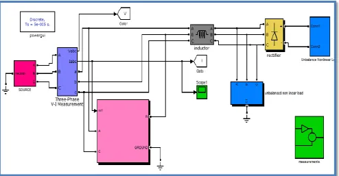
The complete model of power system network with shunt active power filter is presented in figure 5.1 and result were obtained by using MATLAB/Simulink Sim power system Toolbox software.
The overall system model containing the power source, the shunt active power filter and the nonlinear loads is shown in fig. 5.1.
The main components of the system describe below:
The power source, which was designed as a three-phase 11KV/50Hz voltage sources connected together in a Y configuration with neutral and a three phase L branch.
The single-phase nonlinear loads are containing a single phase uncontrolled diode rectifier supplying a series RL load for phase A, a phase uncontrolled diode rectifier supplying a parallel RC load for phase B, a single-phase uncontrolled diode rectifier supplying a series RL loads for single-phase C.
The three phase non-linear load is containing a three phase uncontrolled diode rectifier supplying a series RL load
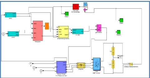
The PWM IGBT voltage source inverter, which contains a three-leg voltage source inverter with neutral clamped DC capacitors and the control scheme, is shown in figure 5.2.
Figure 5.2: Model of Active Power Filter
Despite the fact that the load currents are distorted, with the help of SAPF, the source currents are balanced sinusoids and in phase with their respective voltages. There is a path from the neutral of loads and midpoint of the DC capacitors, the zero sequence current will be appropriately compensated. The sum of the voltages of the DC capacitors (VDC) is maintained nearly constant to the reference DC voltage value (VDC*) by PI controller and then added to the alternative power P loss.
Figure 5.3: Load Current (System without APF) Figure 5.4: Source Current (System with APF)
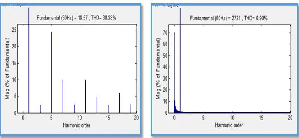
By using APF, the THD of the source current is now 0.90% and magnitude of 5th and 7th harmonics are respectively 0.89% and 0.71% of the fundamental value, thus meeting the limit of harmonic standard of IEEE STD. 519-1992. Fig. 5.5 and fig.5.6 show the Bar representation of signals of figure 5.7 and figure 5.8 respectively. This shows the difference in total harmonic distortion between the system with and without active power filter.
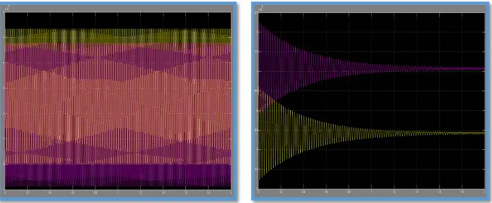
Fig. 5.9 and fig. 5.10 shows the waveform of active and reactive power of system without and with APF respectively.
Figure 5.9: Active and Reactive power (system without APF) Figure 5.10: Active and Reactive Power (system with APF)
Fig. 5.10 shows that when connecting the APF to the system, the reactive power decreases below to Zero. This is proven that APF is a very effective tool to compensate reactive power.
VI.CONCLUSION
Power quality has many problems and that affect system performance. From that harmonic distortion is one of the important power quality problems that affect on the power system. For reduction of harmonics filter are used. Due to certain drawback of passive filter active filter used for harmonic reduction. In case of shunt active power filter reference current generation is main consideration for that various techniques are used. In this paper, the proposed system is based on the new theory of instantaneous power. It is clearly visible from the FFT analysis of the MATLAB/SIMULINK model of the circuit with and without filter that the harmonic component present in the source is compensated with use of filter.
From the analysis of the experimental data, in case of a nonlinear load of rectifier type, one may observe that there are different levels of current distortion produced depending on the load and its control mode, with high values of the total current harmonic distortion and low power factor. Using the active filter, the experimental data show that the total harmonic distortion of current (THDi) decreases from 30.28% to 0.90%. Thus SAPF has been proved to be effective to keep the harmonic content in power lines within the permissible limit.
REFERENCES
[1]. Chandra and B. Singh (1999), “A Review on Active Filters for Power Quality Improvement”, IEEE Trans. on IET, 46,5
[2]. E. H. Watanabe, R. M. Stephan, M. Aredes, New Concepts of Instantaneous Active and Reactive Powers in Electrical Systems with Generic Loads, IEEE Trans. Power Delivery, vol. 8, no. 2, April 1993, pp. 697- 703.
[3]. H. Akagi and T Hatada, ―Voltage balancing control for a three-level diodeclamped converter in a medium-voltage transformerless hybrid active filter,‖ IEEE Trans. Power Electron., vol. 24, no. 3,pp. 571–579, Mar2009.
[4]. H. Akagi, Y. Kanazawa, A. Nabae, Instanataneous Reactive Power Compensator Comprising Switching Devices without Energy Storage Compenents”, IEEE Trans. Industry Applic., vol. 20, May/June 1984.
[5]. H.Akagi, ―Active harmonic filters,‖ Proc. IEEE, vol. 93, no. 12, pp. 212 8–2141, Dec. 2005.
[6]. J. Afonso, “Filtro Ativo Paralelo com Controlo Digital para a Melhoria da Qualidade de Energia Eléctrica”, Ph.D. dissertation, University of Minho, 2000.
[7]. J. Afonso, C. Couto and J. Martins, “Active Filters with Control Based on the p-q Theory”, IEEE Industrial Electronics Society Newsletter, vol. 47, nº 3, Set. 2000, pp. 5-10.
[9]. M. Aredes, E. H. Watanabe, New Control Algorithms for Series and Shunt Three- Phase Four-Wire Active Power Filters, IEEE Trans. Power Delivery, vol 10, no. 3, July 1995, pp. 1649-1656.
[10]. M. Pereira, A. Zenkner, and A. de Oliveira, ―Full range active ac filter with multilevel IGBT converter Conf.Rec.IEEE-PES Transmiss. Distrib. Conf. Expo.: Latin America 2008, pp. 1–6.
[11]. M. Pereira, A. Zenkner, and A. de Oliveira, ―Full range active ac filter with multilevel IGBT converter for transmission and distribution,‖
in Proc.Conf. Rec. IEEE-PES Transmiss. Distrib. Conf. Expo.: Latin America,2008, pp. 1–6.
[12]. N. Hatti, K. Hasegawa, and H. Akagi, ―A 6 6-kV transformerless motor drive using a five-level diode clamped PWM inverter for energy savings of pumps and blowers,‖ IEEE Trans. Power Electron., vol. 24, no. 3,pp. 796–803, Mar. 2009.
[13]. S. Sriangthumrong, H. Akagi, ―A medium-voltage transformerless ac/dc power conversion system consisting of a diode rectifier and a shunt hybrid filter,‖ IEEE Trans. Ind. Appl., vol. 39, no. 3, pp. 874–882, May/Jun. 2003.
[14]. W. Tangtheerajaroonwong, T. Hatada, K. Wada, and H. Akagi, ―Designand performance of a transformerless shunt hybrid filter
integrated into a three-phase diode rectifier,‖ IEEE Trans. Power Electron., vol. 22, no. 5,pp. 1882–1889, Sep. 2007.
BIOGRAPHY
Abhishek Srivastava Belong to UP Received his Bachelor of Technology degree from UCER, Allahabad in 2013. He is pursuing his M.Tech in Electrical Engineering. (Power System) from SHIATS, Allahabad, UP-India.