Self Synchronized Controller for
Grid Connected Voltage Source Converter
Ansu Thomas1, Smitha S.D2
PG Student [Power Systems], Dept. of EEE, Saintgits College of Engineering, Kerala, India1
Assistant Professor, Dept. of EEE, Saintgits College of Engineering, Kerala, India2
ABSTRACT: Grid-connected inverter is typically used to interface the renewable energyinto theutility grid. When significant portion of grid power is inverter-based, it will be advantageous to imitate certain characteristics of the conventional generators. A synchronverteris inverter that mimics a synchronous generator. All grid-connected invertersneed phase locked loop (PLL) to provide the phase, frequency and amplitude of the grid voltage as references to the controller. But, PLL has negative effects on the control performance. In this paper, a radical step is taken to remove the phase locked loop (PLL) by integrating the synchronization function into the synchronverter.This removes the slow element in the system that affects the speed of synchronization. This improves speed of synchronization, reducesthe complexity, cost and computational difficulty of the controller. Theinverter can perform frequency, voltage regulation, real power and reactive power controlwithout using a dedicated phase locked loop.
KEYWORDS: Droop control, grid connection, PLL, renewable energy, synchronization, synchronverter.
I.INTRODUCTION
The day by day increasing demand for energy can create problems for the power distributors, like grid instability. The major portion of the global energy demand can be supplied by the burning of fossil fuels. But due to increasingair pollution, global warming concerns, diminishing fossil fuels and increasing cost; it is necessary tohave renewable energy sources as a future solution. But due to the low efficiency and controllability of the renewable energy system,its connection tothe utility network can lead to grid instability, if it is not properly controlled. To solve this problem, such systems have to employ some sort of interface to inject the synchronized power into the grid. A grid-connected inverter is used typically to interface the renewable energy system to the utility grid [1]. When renewable power generation forms a significant portion of the grid power,it will be advantageous to operate theinverter in the same way as conventional power generators; or at least, to imitate certain characteristics of the conventional generators [2], [3]. A synchronverter is grid-connected inverter that mimics a synchronous generator [4]. It includes the mathematical model of a synchronous machine. A typical synchronverter will have all the good and bad properties of a synchronous generator (SG). Then, thedynamicsseen from the grid side will be same as that of a synchronous generator. Since the real power and reactive power are functions of frequencyand voltage respectively,its controller is, in principle, a power controller with integrated capability of voltage and frequency regulation. Hence, it is able to achieve real power control, reactive power control, frequency regulation and voltage regulation.
In this paper, a radical step is taken to remove the phase locked loop and synchronize the inverter with the grid itself without the need of a dedicated phase locked loop. Sincethe synchronous machine is inherently able to synchronize with the grid, itis possible to integrate the synchronization function into the power controller. It can automatically synchronize with the grid before connection and track the grid frequency after connection. This leads to a compact control structure. The self-synchronizationcapability ofsynchronverter will remove the major nonlinear element in the controller that affects the speed of synchronization. This improves the speed of synchronization, reduces the complexity and computational difficulty of thePLL and reduces the cost of controller. Hence all the functions of synchronverter suchas frequencyregulation, voltage regulation,real power control and reactive power control can be done without the need of dedicated phase locked loop. The closest work in this direction is [16], where no PLL is needed during normal operation; but, a backup PLL is required before connection.
The grid-connected renewable energy systems are presented in Section II. The self-synchronization control is proposed in Section III and the simulation results in Section IV followed by conclusion made in Section VI.
II.SELF SYNCHRONIZAION CONTROL FOR GRID CONNECTED INVERTER
When renewable power generators provide significant portion ofthe grid power, it will be advantageous to operate the inverter in the same way as the conventional generators or at least to imitate certain characteristics of conventional generators. A synchronverter is an inverter that mimics a synchronous generator. The model of synchronous machine can be found in different sources [17]-[18].
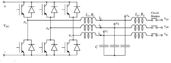
Figure 1: Power part of synchronverter
It consists of mainly a power part and anelectronic part. The power part as shown in Figure 1 includes three inverter legs operated by pulse width modulation (PWM) and LCfilters to reduce the voltageripples during switching operations. The electronic controller as shown in Figure 2 includes the mathematical model of a three phase round rotor synchronous machine represented by,
̈ = ( − − ̇) (1)
= ,sın (2)
= ̇ sın (3)
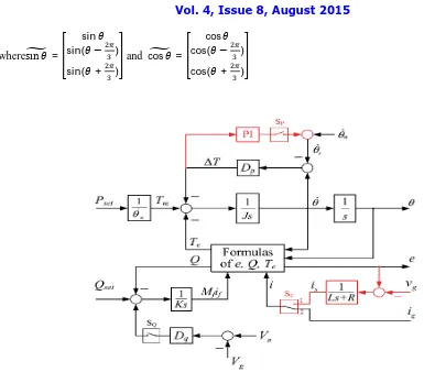
wheresın = sin sin( − )
sin( + )
and cos =
cos cos( − )
cos( + )
Figure 2: Electronic part of self-synchronizedsynchronverter
, , , θ and Q are the mechanical torque, electromagnetic torque, three-phase generated voltage, rotor angle, and reactive power of synchronverter respectively. J is the virtual moment of inertia of therotating parts,if is field excitation
current and Mfis the maximum mutual inductance between the stator and the field windings. ̇is the virtual angular
speed of the machine and i is the stator current flowing out of the machine. It is assumed that number of pole pairs for each phase is 1. The self-synchronization function can be achieved by means of :
a)Virtual current isis generated from the voltage error between generated voltage (e) and grid voltage (vg) and the
current that is fed to the controller can be either the virtual current isor the grid currentig.
b) A PI controller is added to regulate ΔT of the frequency droop block to zero and to generate the reference frequency ̇ for the controller.
3.1Initial synchronization operation
The per-phase model of asynchronverter, connected to an infinite bus is shown in Figure 4.
Figure 4: Per phase model of SG connected to infinite bus
P = sin(θ − θ )(5)
Q = [E cos θ − θ −V ] (6)
WhereE is the induced voltage amplitude of the SG, Vg is the amplitude of the infinite bus voltage, is the phase of
grid voltage, θ is the phase of SG and Xsis the synchronous reactance of the SG.
From equations (5) and (6) suppose when θ and E are controlled to be
E = V(7)
θ=θ (8)
then there is no real power or reactive power exchanged between the connected SG and grid. In reverse case, if P and Q
are controlled to be zero, then the condition (7) and (8) are satisfied and the generated voltage e is same as that of grid voltage vg. Thus, phase frequency and amplitude of generated voltage is same as that of grid. Under this condition the
SG can be connected to or disconnected from the grid without causing large transients. This principle can be used for synchronizing asynchronverter with the grid before connection.
For initial synchronization operation, it is necessary to operate the synchronverter under set mode with Psetand Qsetequal
to zero. As a result, the condition (7) and (8) can be satisfied when it is connected to the grid. When switch SP is turned
ON and SQ is turned OFF the synchronverter is operated under the set mode. If Psetand Qsetare both 0, then the
operation mode is the self-synchronization mode and the inverter is able to synchronize with the grid. But the grid currentigis 0 until the circuit breaker is closed. A virtual per-phase inductor Ls+R is introduced to connect the
synchronverter with the grid in order to mimic the process of connecting a physical machine to the grid. The virtual current is routed into the controller via the switch SCthrown at position 1. The virtual current isis given by
i = e−v (9)
Using this virtual current, and Q can be calculated according to (2) and (4). Virtual impedance can be chosen within a wide range. Small values can speed up the synchronization operation but with a large transient current. When the virtual current is driven to zero, then the synchronverter is synchronized with the grid. Then, the circuit breaker can be turned on to connect it to thegrid. After circuit breaker is closed, the Switch SC should be turned to position 2 so that the
grid current ig is fed into the controller. Hence no PLL is required for the initial synchronization operation.
3.2. OPERATION AFTER CONNECTING TO GRID
3.2.1 FREQUENCY CONTROL
The timeconstant ᴦf= of the frequency loop is much smaller than the time constant ᴦv = θ̇ of the voltage loop.
Hence, while considering the dynamics of frequency loop, Mfifcan be assumed as constant. Moreover, from equation
(5), the real power generated by the synchronverter is proportional to sinδ. As a result, the electromagnetic torqueTeis
also proportional to sinδ. Suppose if the grid frequency θ̇ decreases, then the power angle δ and the electromagnetic
torque Teincreases. Hence the input to the integrator block decreases and the synchronverter frequency θ̇decreases.
3.2.2 REAL POWER CONTROL (SET AND DROOP MODE)
When switch SP is turned ON, PI controller will be inserted in the frequency droop control loop. Hence, ΔT is
controlled to 0 under the steady state condition. Thus Te becomes equal to Tm and θ̇ is controlled as
θ̇=θ̇= θ̇ + ∆θ̇(10)
where∆θ̇ is the output of PI controller. Thus the power angle δ settles down at a constant value that results in P= Pset.
This mode of operation is called as the set mode. The set mode for the real power and reactive power is represented as
P mode and Q mode respectively in this paper.
When the Switch SP is turned OFF, then the PI controller is taken out of the loop and the synchronverter is operated in
the frequency droop mode (represented as PDmode in this paper). The frequency droop coefficient is given by,
Dp=−
∆
∆ ̇ (11)
where∆ ̇ is the frequency deviation of the synchronverter from the nominal frequency.
3.2.3 REACTIVE POWER CONTROL (SET AND DROOP MODE)
The Switch SQ in voltage droop loop will control the reactive power flow. When Switch SQis in OFF condition, the
field excitationMfifisvaried depending on the tracking error between Qset and Q by means of an integrator with gain 1/K
Therefore, the generated reactive power Qtracks exactly the set-pointQset irrespective of the voltage difference
betweenVnand Vg. This operation mode is called as the set mode for the reactive power control (represented as Q mode
in this paper).
When Switch SQ is in ON condition, then the voltage droop function is enabled and depending on the voltage error
∆V = V −V, the field excitation Mfifis varied. Hence, the reactive power Q does not track exactly Qset, but with
steady-state error∆Q = Q −Q. The voltage droop coefficient is given by,
Dq=−
∆ ∆ (12)
This operation mode is called as the voltage droop mode (represented as QDmode in this paper).
IV.SIMULATION RESULTS
The proposed control strategy was verified in MATLAB 7.9/Simulink/SimPowerSystems. The parameters are given in Table 1. The inverter is connected to the grid via a step-up transformer. HereDp= 0.2026 is chosen which implies that a
drop of 0.5% in the frequency (from the nominal frequency) causes the torque to increase by 100% (of the nominal power) and the voltage droop coefficient is chosen asDq= 117.88 so that drop of 5% in the voltage causes an increase of
100% of reactive power.
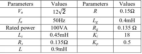
Table 1: Parameters used for simulation
Parameters Values Parameters Values
Vn 12√2 R 0.15Ω
fn 50Hz Lg 0.4mH
Rated power 100VA Rg 0.135 Ω
Ls 0.45mH Ki 18
Rs 0.135Ω Kp 0.5
L 0.9mH
4.1 SELF SYNCHRONIZATION CONTROL
At simulation time t=0, switch SC in Position 1, SP turned ON, SQ turned OFF, and circuit breaker in OFF condition,
The set point for real power Pset = 100W was applied at t = 5 s and the set-point for the reactive power Qset= 100Var
was applied at t = 10s. The PD mode was enabled at t=15 s by turning Switch SP OFF and grid frequency was stepped
up to fg=50.2 Hz (i.e. increased by 0.4%) at t= 20 s.The QD mode was enabled at time t=25s. The grid frequency
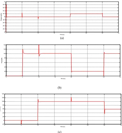
returned to nominal value at t=30s and the grid voltage was set to be 2% higher than the nominal grid voltage at t=30s. The simulation was stopped at time t=35s. The entire system responses from t=0 to t=35s are shown in Figure 5.
At first synchronverter was operated in the self-synchronization mode to synchronize itself with the grid. When virtual current isis driven to zero, the synchronverter is synchronized with the grid. After circuit breaker is closed, virtual
current was replaced by grid current. The transient current at the moment of circuit breaker closure is less than 10mA, and hence there was no problem to connect it to the grid.Synchronverter tracked the grid frequency very well without any problem. There are transient peaks in the frequency and power curve at each event. This is expected, similar to the
(a)
(b)
(c)
Figure 5: Simulation results when grid frequency is increased to 50.2Hz from t=20 to t=30s
and grid voltage is increased by 2% from t=30 to t=35s (a) Synchronverter frequency (b) Real power (c) Reactive power
0 5 10 15 20 25 30 35
49 49.2 49.4 49.6 49.8 50 50.2 50.4 50.6 50.8 51 Time(s) F re q u e n c y (H z ) Frequency
0 5 10 15 20 25 30 35
-20 0 20 40 60 80 100 120 140 Time(s) P o w e r( W ) Frequency
0 5 10 15 20 25 30 35
change in the speed of a synchronous machine as the operating condition changes. The real power and reactive power generated tracked exactly the set power during the set mode of operation. The frequency also tracked very well in the droop modes, but the real power changed with the grid frequency, as expected. When the PD mode was enabled and the
frequency was increased to fg = 50.2 Hz (ie, 0.4% higher than nominal value), then the real power dropped by 80W;
ie . %
. %= 80% of the nominal value. When grid frequency returned to nominal value, the power quickly jumped back to
set value. Similarly, when QD mode was enabled and grid voltage is increased by 2%, the reactive power dropped by 40
Var, i.e., %
%= 40% of the nominal power.
4.2 COMPARITIVE STUDY OF SYNCHRONVERTER WITH AND WITHOUT PLL IN TERMS OF SETTLING TIME
As grid frequency is continuously changing, the settling time of frequency curve is of great importance. The frequency responses when the grid frequency is increased by 0.2 Hz at t=20s is simulated for synchronverter with and without PLL.
(a)
(b)
Figure 6: Simulation results when grid frequency is increased to 50.2Hz from t=20 to t=30s (a) Synchronverter frequency without using PLL (b) Synchronverter frequency with a PLL
Simulated results in Figure 6 shows that in the self-synchronization control, the frequency settles down accurately within 0.1s whereas the synchronverter frequency with PLL settles down at 0.8s. Thus the speed of synchronization is improved considerably in the proposed scheme.
19.8 19.9 20 20.1 20.2 20.3
49 49.2 49.4 49.6 49.8 50 50.2 50.4 50.6 50.8 51 Time(s) F re q u e n c y (H z ) Frequency
19.8 20 20.2 20.4 20.6 20.8 21 21.2 21.4 21.6 21.8
VI.CONCLUSION
A self-synchronized inverter (called synchronverter) has been developed to integrate the renewable energy system to grid system. The self-synchronization control of grid connected inverter removes the need of a dedicated phase locked loop. This completely eliminates the problems that are associated with a conventional PLL. Thus, it simplified the controller, reduced the difficult and complexity in tuning the parameters of PLL,reduced the development cost of PLL. It is able to synchronize with the grid before connection and trackthe gridfrequency automatically after connection. Also, it is able to operate in different modes of power control without using the PLL. The controller is, in principle, a powercontroller with integrated capability offrequency and voltage regulation together with self-synchronization control. This leads to a compact control structure. Further, the speed of synchronization improved considerably in the self-synchronization control.
REFERENCES
.
[1] J. M. Carrasco, L. G. Franquelo, J. T. Bialasiewicz, E. Galvan, R. C. Portillo-Guisado, M. A. M. Prats, J. I. Leon, and N. Moreno-Alfonso,
“Power-electronic systems for the grid integration of renewable energy sources: A survey,”IEEE Trans. Ind. Electron., vol. 53, no. 4, pp. 1002–1016, Aug. 2006.
[2] H.-P. Beck and R. Hesse, “Virtual synchronous machine,” in Proc. 9th Int. Conf. EPQU, 2007, pp. 1–6.
[3] J. Driesen and K. Visscher, “Virtual synchronous generators,” in Proc.IEEE Power Energy Soc. Gen. Meeting–Conversion and Delivery of
Electrical Energy in the 21st Century, Jul. 2008, pp. 1–3.
[4] Q.-C. Zhong and G. Weiss, “Synchronverters: Inverters that mimic synchronous generators,” IEEE Trans. Ind. Electron., vol. 58, no. 4, pp.
1259–1267, Apr. 2011.
[5] F. Blaabjerg, R. Teodorescu, M. Liserre, and A. Timbus, “Overview of control and grid synchronization for distributed power generation systems,”IEEE Trans. Ind. Electron.,vol. 53, no. 5, pp. 1398–1409, Oct. 2006.
[6] .J. Svensson, “Synchronisation methods for grid-connected voltage sourceconverters,” IEE Proc. Generat., Transmiss. Distrib., vol. 148, no.
3,pp. 229–235, May 2001.
[7] M. Ciobotaru, R. Teodorescu, and F. Blaabjerg, “A new single-phase PLL structure based on second order generalized integrator,” in Proc.
37th IEEE Power Electron. Spec. Conf., 2006, pp. 1–6.
[8] M. Karimi-Ghartemani and M. Iravani, “A new phase-locked loop (PLL) system,” in Proc. 44th IEEE Midwest Symp. Circuits Syst., 2001,
pp. 421–424.
[9] Q. Zhang, X.-D. Sun, Y.-R. Zhong, M. Matsui, and B.-Y. Ren, “Analysis and design of a digital phase-locked loop for single-phase
grid-connected power conversion systems,” IEEE Trans. Ind. Electron., vol. 58, no. 8,pp. 3581–3592, Aug. 2011.
[10] P. Rodriguez, J. Pou, J. Bergas, J. Candela, R. Burgos, and D. Boroyevich, “Decoupled double synchronous reference frame PLL for power
converters control,” IEEE Trans. Power Electron., vol. 22, no. 2, pp. 584–592, Mar. 2007.
[11] L. Harnefors, M. Bongiorno, and S. Lundberg, “Input-admittance calculation and shaping for controlled voltage-source converters,” IEEE
Trans.Ind. Electron., vol. 54, no. 6, pp. 3323–3334, Dec. 2007.
[12] D. Jovcic, L. Lamont, and L. Xu, “VSC transmission model for analytical studies,” in Proc. IEEE Power Eng. Soc. Gen. Meet., Jul. 2003, vol.
3,pp. 1737–1742.
[13] C. da Silva, R. Pereira, L. da Silva, G. Lambert-Torres, B. Bose, andS. Ahn, “A digital PLL scheme for three-phase system using
modifiedsynchronous reference frame,” IEEE Trans. Ind. Electron., vol. 57, no. 11,pp. 3814–3821, Nov. 2010.
[14] M. KarimiGhartemani, A. Khajehoddin, P. Jain, and A. Bakhshai, “Problemsofstartup and phase jumps in PLL systems,” IEEE Trans.
PowerElectron., vol. 27, no. 4, pp. 1890–1838, Sep. 2011.
[15] R. Santos Filho, P. Seixas, P. Cortizo, L. Torres, and A. Souza, “Comparison of three single-phase PLL algorithms for UPS applications,”
IEEETrans. Ind. Electron., vol. 55, no. 8, pp. 2923–2932, Aug. 2008.
[16] L. Zhang, L. Harnefors, and H.-P. Nee, “Power-synchronization controlof grid-connected voltage-source converters,” IEEE Trans. Power
Syst.,vol. 25, no. 2, pp. 809–820, May 2010.
[17] P. Kundur, Power System Stability and Control. New York: McGraw-Hill, 1994.