Simulation and Dynamic Analysis of Grid
Connected Wind Energy System use Solar
Power Based STATCOM
Anly Abraham
1, S. Annadurai
*2Assistant Professor, Dept. of EEE, Jerusalem College of Engineering,Chennai, Tamil Nadu, India1 Assistant Professor, Dept. of EEE, Bharath University, Chennai, Tamil Nadu, India2
Corresponding Author
ABSTRACT: This paper presents the modelling and simulation of grid connected wind energy system using solar power based STATCOM compensation. This scheme can be improve the power quality of grid connected wind energy system using solar power. The injection of the wind power into the grid affects the power quality of the system. Some of the power quality issues like voltage sag and harmonics are considered. In this proposed system. Simulation model of 3-phase system with compensation and without compensation are modelled and simulated. In this system a solar powered STATCOM is used and it can improve the grid voltage and reduce the harmonics. The complete system is modelled and simulated in the MATLAB/ SIMULINK environment. The sustainable and renewable model and design can promote green energy systems in the future.
KEYWORDS: Induction generator, STATCOM, wind turbine (WT), wind generator.
I. INTRODUCTION
Both electric utilities and end users of electric power are increasingly concerned about the quality of power. Power quality can be defined as "any power problem manifested in voltage, current and frequency that results in failure or mal-operation of the customer equipment". Injection of the wind power into an electric grid affects the power quality. The group of devices used for mitigation of power quality problems is known by the name of customer Power Devices (CPDs). The family of compensating devices mainly has the following members: Static Synchronous Compensator (STATCOM), Dynamic Voltage Restorer (DVR) and Unified Power quality Conditioner (UPQC). The work analyses the performance of STATic Compensator (STATCOM) with a battery energy storage system (BESS) which is connected at the point of common coupling of wind energy generating system and the existing power system to mitigate the power quality issues. During the normal operation, wind turbine produces a continuous variable output power [1], [2]. These
II. TOPOLOGY OF POWER QUALITY IMPROVEMENT
The STATCOM is a three-phase voltage source inverter having the capacitance on its DC link and connected at the point of common coupling. The STATCOM injects a compensating current of variable magnitude and frequency component at the bus of common coupling. Here the utility source, wind energy system and STATCOM with BESS is connected to the grid. The STATCOM based current controlled voltage source inverter injects the current into the grid in such a way that the source current are harmonic free and they are in phase-angle with respect to source voltage. The injected current will cancel out the reactive part and harmonic part of the load and induction generator current, thus it improves the power quality. This injected current generation is by proper closing and opening of the switches of voltage source inverter of STATCOM.
A. Wind Energy Generating System
In this configuration, wind generations are based on constant speed topologies with pitch control turbine. The induction generator is used in the proposed scheme because of its simplicity, it does not require a separate field circuit, it can accept constant and variable loads, and has natural protection against short circuit. The available power of wind energy system is presented as:
Pwind = ρ A (1)
Where ρ = air density (kg/m3
), A = area swept out by turbine blade (m2), = wind speed (m/s).
It is not possible to extract all kinetic energy of wind. Thus it extract a fraction of power called power coefficient Cp of
the wind turbine, and is given by:
Pmech = Cp Pwind (2)
The mechanical power produced by wind turbine is given by
Pmech = ρ (3)
Where R = Radius of the blade {m}.
III.BESS-STATCOM
The battery energy storage system (BESS) is used as an energy storage element for the purpose of voltage regulation. The BESS will naturally maintain dc capacitor voltage constant and is best suited in STATCOM since it rapidly injects or absorbs reactive power to stabilize the grid system. It also controls the distribution and transmission system in a very fast rate [11].
When power fluctuation occurs in the system, the BESS can be used to level the power fluctuation by charging and discharging operation. The battery is connected in parallel to the dc capacitor of STATCOM [3], [5], [6].
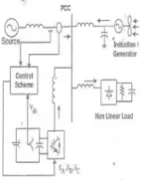
A. System Operation
The shunt connected STATCOM with battery energy storage is connected with the interface of the induction generator and non-linear load at the PCC in the grid system. The Fig 1 represents the system operational scheme in grid system. The STATCOM compensator output is varied according to the control strategy, so as to maintain the power quality norms in the grid system. The current control strategy for STATCOM is the Bang-Bang control scheme and fuzzy logic control scheme that defines the functional operation of the STATCOM compensator in the power system. A single STATCOM using insulated gate bipolar transistor is proposed to have a reactive power support, to the induction generated and to the nonlinear load in the grid system.
A. Control Scheme
Fig.2. Bang-Bang Current Controller
The control scheme approach is based on injecting the currents into the grid using―bang-bang controller‖ [1]. The controller uses a hysteresis current controlled technique as shown in Fig 2. Using such technique, the controller keeps the control system variable between boundaries of hysteresis area and gives correct switching signals for STATCOM operation. In this scheme the hysteresis band selected as 0.08. The control algorithm needs the measurements of several variables such as three-phase source current, DC voltage inverter current with the help of sensor [10]. The current control block, receives an input of reference current and actual current are subtracted so as to activate the operation of STATCOM in current control model [4].
c. Grid Synchronization
In three-phase balance system, the RMS voltage source amplitude is calculated at the sampling frequency from the source phase voltage (Vsa, Vsb, Vsc) and is expressed as sample template (sampled peak voltage), Vsm:
Vsm = {2/3(Vsa 2
+ Vsb2 +Vsc2)} (4)
The in-phase unit vectors are obtained from AC source phase voltage and the RMS value of unit vector as shown below:
Usa = Vsa/Vsm (5) Usb = Vsb/Vsm (6) Usc = Vsc/Vsm (7)
IV. MAT LAB SIMULINK MODEL OF MSGCWES
The MAT LAB SIMULINK is a powerful software tool, which is implemented in this system.
A 3-Phase circuit without using the STATCOM is shown in fig.2(a). There are two loads at the receiving end. At t=0.3sec, the voltage decreases due to the connection of the second load as shown in fig 2(b) and RMS voltage is shown in fig.2(c). The RMS current is shown in Fig 2(d). The real power is shown in Fig 2(e) and reactive power is shown in Fig 2(f).
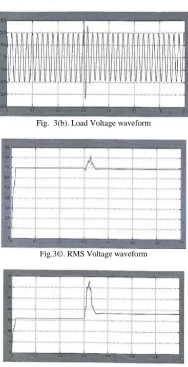
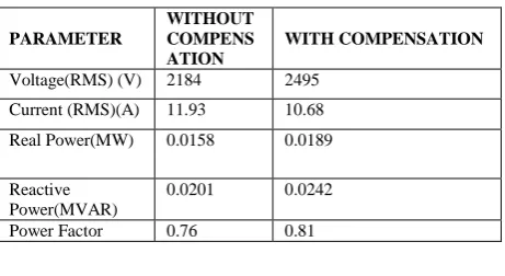
The 3-phase, 2 bus system with STATCOM is shown in simulation circuit fig 3(a). The STATCOM inject the reactive power through a transformer to compensate the voltage drop in the line. The load voltage is shown Fig 3(b). RMS value of load Voltage and load current are shown in fig 3(c) and 3(d) respectively. The real and reactive power are shown in Fig 3(e) & 3(f) respectively. The load Voltage reaches the normal value due to the injection from the STATCOM [7-9]. The 3 STATCOM system with Non-linear load shown in Fig 4(a). The control circuit corresponding space vector modulation is shown in Fig 4(a). The Voltages in a,b,c frame are converted in dq frame using part transformation later dq frame is transformed in to a,b,c frame. The instantanious and RMS load voltages are shown in Fig 4(f) and 4(g) respectively. Table 1 gives the comparison of parameters with and without compensation. The FFT analysis is done for the output voltage and the spectrum is shown in fig 4(b). The THD is 8.69 %.
Fig 2(a) Circuit without STATCOM.
Fig.2©. RMS Voltage waveform
Fig.2(d). RMS Load Current waveform
Fig.2(e). Real Power waveform
Fig. 3(a) 3-phase, 2-bus System with STATCOM
Fig. 3(b). Load Voltage waveform
Fig.3(e ). Real Power waveform
Fig.3(f). Reactive Power waveform
Fig.4(a). Circuit diagram with Statcom
Fig.4©. RMS Load Voltage waveform
Fig.4(d). RMS Load Current waveform
TABLE 1
COMPARISON OF RESULTS
V. CONCLUSION
This paper presented the STSTCOM based compensation scheme, for power quality improvement in the grid connected wind energy system, with non-linear loads. The operation of this control scheme is developed with MATLAB SIMULINK environment (version MATLAB 7.9). The load voltage is successfully compensated using SVM based STATCOM. The control is easy, since Vd and Vq are static. The simulation results match with the
theoretical results.
REFERENCES
[1] Sharad W. Mohod, Mohan V. Aware, " A STATCOM control scheme for grid connected wind energy system for power quality improvement,”
IEEE SYSTEMS JOURNAL, VOL.4, NO. 3, SEPTEMBER 2010.
[2] Babu T.A., Sharmila V., "Cefotaxime-induced near-fatal anaphylaxis in a neonate: A case report and review of literature", Indian Journal of Pharmacology, ISSN : 0253-7613, 43(5) (2011) pp.611-612.
[3] C. Han, A. Q. Huang, M. Baran, S. Bhattacharya, and W. Litzenberger, "STATCOM impact study on the integration of a large wind farm into a weak loop power system," IEEE Trans. Energy Conv., vol. 23, no. 1, pp.226-232, Mar. 2008.
[4] Valiathan G.M., Thenumgal S.J., Jayaraman B., Palaniyandi A., Ramkumar H., Jayakumar K., Bhaskaran S., Ramanathan A., "Common docking domain mutation e322k of the erk2 gene is infrequent in oral squamous cell carcinomas", Asian Pacific Journal of Cancer Prevention, ISSN : 1513-7368, 13(12) (2012) pp.6155-6157.
[5] Sharad W. Mohod,, and Mohan V. Aware, " Micro wind power generator with battery storage," IEEE SYSTEMS JOURNAL, VOL. 6, NO. 1, March 2012.
[6] Mani Sundar N., Krishnan V., Krishnaraj S., Hemalatha V.T., Alam M.N., 'Comparison of the salivary and the serum nitric oxide levels in chronic and aggressive periodontitis: A biochemical study", Journal of Clinical and Diagnostic Research, ISSN : ISSN - 0973 - 709X, 7(6) (2013) pp.1223-1227.
[7] S.W.Mohod and M.V.Aware, "Power quality issues & it's mitigation technique in wind energy conversion," in Proc. of IEEE int.Conf.Quality Power & Harmonic, Woliongong, Australia,2008.
[8] Thirunavukkarasu A.B., Chandrasekaran V., 'Efficacy of anti-scorpion venom serum over prazosin in severe scorpion envenomation: Is the current evidence enough", Journal of Postgraduate Medicine, ISSN : 0022-3859, 57(1) (2011) pp.83-84.
[9] T.Kinjo and T.Senjyu, "Output leveling of renewable energy by electric double layer capacitor applied for energy storage system," IEEE Trans.Energy Conv., Vol. 21 ,no. 1, Mar. 2006.
[10] Subbaraj G.K., Kulanthaivel L., Rajendran R., Veerabathiran R., "Ethanolic extract of Carum carvi (EECC) prevents N-nitrosodiethylamine induced phenobarbital promoted hepatocarcinogenesis by modulating antioxidant enzymes", International Journal of Pharmacy and Pharmaceutical Sciences, ISSN : 0975 - 1491, 5(S1) (2013) pp.195-199.
[11] R.S.Bhatia, S.PJain, D.K.Jain, and B.singh, "Battery energy storage system for power conditioning of renewable energy sources," in Proc. int. Conf. Power Electron Drives System, vol. 1, pp.501-506, Jan . 2006.
[12]B Karthik, S Rajeswari, Design and Analysis of a Transceiver on a Chip for Novel IR-UWB Pulses, Middle-East Journal of Scientific Research 19 (6), PP 817-820, 2014.
[13]Shriram, Revati; Sundhararajan, M; Daimiwal, Nivedita; , Application of High & Low Brightness LEDs to Human Tissue to Capture Photoplethysmogram at a Finger TipRed, V-620,PP 700.
[14]Muralibabu, K; Sundhararajan, M; , PAPR performance improvement in OFDM system using DCT based on adjacent symbol groupingTrans Tech Publ, Applied Mechanics and Materials, V-550,PP 204-209, 2014.
[15]sivaperumal, s; sundhararajan, m; , advance feature extraction of mri brain image and detection using local segmentation method with watershed. [16]MURALIBABU, K; SUNDHARARAJAN, M; , PAPR reduction using DCT based sub carrier grouping with Companding Technique in OFDM
system.
[17]Kanniga, E; Srikanth, SMK; Sundhararajan, M; , Optimization Solution of Equal Dimension Boxes in Container Loading Problem using a Permutation Block AlgorithmIndian Journal of Science and Technology, V-7, I-S5,PP 22-26, 2014
PARAMETER
WITHOUT COMPENS ATION
WITH COMPENSATION
Voltage(RMS) (V) 2184 2495
Current (RMS)(A) 11.93 10.68
Real Power(MW) 0.0158 0.0189
Reactive Power(MVAR)
0.0201 0.0242
![Fig 3(e) & 3(f) respectively. The load Voltage reaches the normal value due to the injection from the STATCOM [7-9]](https://thumb-us.123doks.com/thumbv2/123dok_us/7788595.1289558/4.595.219.377.625.749/fig-respectively-voltage-reaches-normal-value-injection-statcom.webp)