Flexible automation system for industrial
transformer testing
S.Pragadheesh Raj
1, M.Praveen Kumar
2, S.Subash
3B.E Student, Dept. of Robotics and Automation, PSG College of Technology, Coimbatore, Tamil Nadu, India1,2,3
ABSTRACT:Transformers play an important role in the power system of any industry. They are often in operation for a long time and only stop working during power interruptions and maintenance. Hence the testing of transformers is of prime significance to ensure their proper functionality. The main purpose of the paper is to develop a flexible automation system based generic Transformer Test Rig. The test rig is controlled and monitored with a PLC and a dedicated computer. The application of this proposal is mainly for testing dry type industrial transformers. The term ‘generic’ signifies the possibility to test wide range of transformers (3-Phase/1-Phase, 1-Phase/1-Phase and the like). The number of tappings of the transformers is an important factor to be considered. The Automated Test Rig performs the basic specified tests and prints the report after every test has been performed indicating defective transformers at the testing phase itself.
KEYWORDS: Transformer testing, PLC, Siemens S7-1200, AC-DC Conversion, Ladder Logic, Automation
I.INTRODUCTION
Simplification of engineering and precise control of plant processes can result in significant cost savings. The most cost-effective way, which can pay big dividends in the long run, is flexible automation. A planned approach towards integrated control systems is the key factor of technological improvement. It requires conscious effort on the part of plant managers to identify areas where automation can result in better deployment/utilization of human resources and savings in man-hours, down time. Automation need not be high ended and too sophisticated.It is the phased, step-by-step effort to automate, employing control systems tailored to one’s specific requirements that achieves the most attractive results. That is where Industrial electronics has been a breakthrough in the field of automation and control techniques.
Transformer testing plays an important role in determining its performance. The conventional methods have been followed in various industries to test transformers. The various tests performed on a transformer include winding resistance test, voltage regulation, primary and secondary voltage measurements, primary and secondary current measurements, core and copper losses, efficiency and the like. Manual testing methods with the use of test equipment requires basic skillset and also consumes lot of time. Repeated routine test also provides fatigue to the operator which affects the quality of the products produced. This paper provides an automation solution to overcome the challenges. The automated test rig is aimed at testing the transformers with minimal human intervention and increase the testing cycle time. Automation systems thereby increase the accuracy and precision of the test results produced hence helps to maintain the quality.
II.PROGRAMMABLE LOGIC CONTROLLERS
Advantages of Programmable Controllers
1. Programmable controllers are made of solid state components and hence provide high reliability.
2. They are flexible and changes in sequence of operation can easily be incorporated due to programmability. They may be modular in nature and thus expandability and easy installation is possible.
3. Use of PLC results in appreciable savings in Hardware and wiring cost.
4. They are compact and occupy less space.
5. It has total protections against obsolescence and has wide scope for upgradation.
III. SYSTEM OVERVIEW
The test rig has been implemented for no load tests with future scope of addition of other required tests. The Tests performed on no load condition
I. Input and Output voltages II. Input and Output current III. Input and Output Power
Test rig to be developed for testing of a wide range of transformers with a minimum of 3 to 5 tappings.Transformer test schematic developed with consultation of the various manufacturers for typical testing 3-Phase / 1-Phase Transformer. Basic requirements for test rig have been described in detail in the schematic. Practical testing of 3-Phase transformer and 1-Phase transformer were demonstrated in the industry.
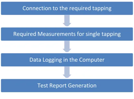
Fig 1 Process Flow Diagram
Fig 1 describes the complete sequence of the testing process performed. The initial installation and connections must be manually done. The process can be started manually or programmed to be automated. The generated test report will also be printed.
Input Elements:The voltage and the current are converted to DC +10V to -10V and 4-20mA respectively with suitable signal conditioning module. The voltages which are more than the rating of the module are stepped down with potential transformers.
Connection to the required tapping
Required Measurements for single tapping
Data Logging in the Computer
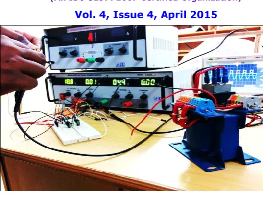
Fig 2 Prototype of the Automated Test Rig
Fig 2 shows the developed prototype of the proposed system. It shows the test transformer and the working of the signal conditioning module.
IV. SIGNAL CONDITIONING
In electronics, signal conditioning means manipulating an analog signal in such a way that it meets the requirements of the next stage for further processing. Most common use is in analog-to-digital converters.
In control engineering applications, it is common to have a sensing stage (which consists of a sensor), a signal conditioning stage (where usually amplification of the signal is done) and a processing stage (normally carried out by an ADC and a micro-controller). Operational amplifiers (op-amps) are commonly employed to carry out the amplification of the signal in the signal conditioning stage.
The signal condition module developed consists of an op-amp Schmitt trigger and an inverting amplifier. The reference voltage of the Schmitt trigger is variable. The voltage of the test transformer is stepped down by the potential transformer to the required input voltage of the signal conditioning module. Schmitt trigger is a regenerative type of a comparator. It produces voltage pulse wave according to the set reference voltage. The duty cycle of the pulsed wave changes corresponding to the input voltage which is measured using a microcontroller. The microcontroller with additional hardware provides a pure DC voltage in the range of 0-10V compatible with analog measurement of the PLC. The PLC program gives the voltage of the test transformer based on the output form the signal conditioning module.
Fig 3 depicts the pulse wave output after amplification. The duty cycle of the wave changes according to the set reference voltage. The reference voltage is varied in accordance with the test transformer output voltage.
V. HUMAN MACHINE INTERFACE
The user interface, in the industrial design field of human–machine interaction, is the space where interactions between humans and machines occur. The goal of this interaction is to allow effective operation and control of the machine from the human end, whilst the machine simultaneously feeds back information that aids the operator’s decision making process. A HMI is also employed for a better visualization and control of the process.
Fig 4 HMI Screen Configuration for Single Phase Testing
Fig 4 shows the HMI screen configuration which inputs the required parameters to the Ladder Diagram. The defective products are indicated by a status Red LED
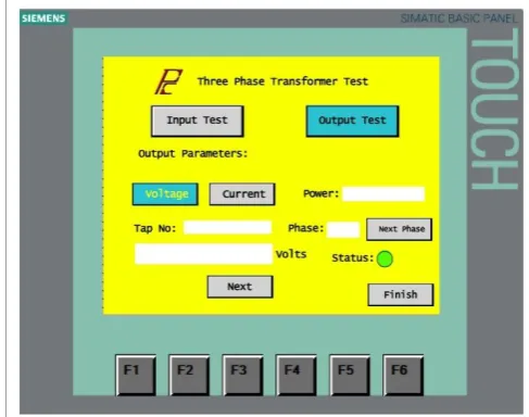
Fig 5 HMI Screen configuration for Three Phase transformer testing
VI. CONCLUSION
Thus the flexible automation system setup would minimize the labour required for testing, cycle time of testing which can eventually enhance productivity. There is a lot of scope for future upgradation. Addition features such as frequency measurement, core temperature measurements have been proposed for the next phase prototype. This setup can also be modified to be used with existing energy meters with a MODBUS RTU RS-485 Interface because it can directly communicate with the PLC. This helps in integration with existing technology for a better performance.
REFERENCES
[1]A. Hossain, M. H. Rashid, The Hardware and Software Interface of a Programmable Logic Grade Process Controller to an Industrial Control System, IEEE Conference 1990, USA, pp. 1862- 1868
[2] T. Krairojananan, S. Suthapradit, A PLC Program Generator Incorporating Sequential Circuit Synthesis Techniques. IEEE, 399-402, USA [3] K. Ji, Y. Dong, Y. Lee, J, Lyoul, Reliability Analysis Safety Programmable Logic Controller, SICE-ICASE International Joint Conference, Oct. 18-21, 2006 Korea
[4] A.R. Alae, M.M. Negm, M. Kassas, A PLC Based Power Factor Controller for a 3-Phase Induction Motor, IEEE Transactions on Energy Conversion, USA, 1065-1071, 2000