Jannu Rajesh
1, kranthi
21
M.Tech student,PE, CITS, Warangal, Telangana,,India.Mail Id:[email protected]
2Associate professor,EEE DEPT, CITS, Warangal, India
ABSTRACT:An innovative model of integrated inverter/converter circuit is proposed for control of three-phase permanentmagnet synchronous motor used as a drive for EV and HEV applications. Three-phase permanent magnet synchronousmotor is having a capability to permit the Dual-mode operation of motoring mode and converter mode effectively.In the inverter mode, the integrated circuit acts as inverter only. But, in the converter mode, the integrated circuit.The proposed control technique is to useinterleaved control to significantly reduce the current ripple and thereby reducing the losses and thermal stress under heavy-loadcondition. The performance of the proposed circuit is available by using simulation of MATLAB/SIMULINK software
KEYWORDS:Electric Vehicle (EV), Hybrid Electric Vehicle (HEV), Permanent Magnet Synchronous Motor (PMSM),Internal Combustion Engine (ICE)
I. INTRODUCTION
Electric transportation isn't a brand new occurrence in fact; the idea has existed for over hundred years. However,provided growing environmental sensitivities, long-term supplyconcerns, fossil fuel costs and enhanced technology, there's a strong inspiration to further accelerate the market segment.Government laws like the 130g/km (and futureplanned 95g/km) CO2 regular emission limits
for automobileproducers in Europe are catalysts behind brand new electrified transportation options. With the adoption ofmore electronics, vehicles start to be more secure, display higher performance, and therefore are better. Electric transportation isa crucial component within the all round renewable energy landscape.Energy for charging is anticipated to come from sustainable energy sources as wind, solar or maybe plants were powered by water. Home andpublic charging stations will also become more prevalent andcan take advantage of off-peak charging
(night time) and greenish power sources like wind. With a complete range ofanalog and embedded processing solutions, TI is actually at theforefront of helping to take more, affordable, and safer effective electricity transportation strategies to promote. TI"ssolutions for this industry range from optimized anddedicated integrated circuits to complete system-level solutions tohelp our clients optimize as well as accelerate product development. TI"s knowledge in several markets such asindustrial control, manufacturing motor drives, digital powersupplies, wise metering as well as grids, wired and wirelesscommunications, consumer electronics, along with power efficiencyallows engineers to meet increasing requirements for higher speeds,greater precision, lower energy and more powerful equipment -all while maintaining the high standards of quality andreliability that the motor vehicle and transportation market needs. The electric vehicle process and hybrid is made ofseveral modules to create the energy storage system and drivetrain. The electric battery block (typically a Li-ion chemistry in theassortment of 400 V) is actually managed as well as monitored by the batterymanagement structure (BMS) and energized via an onboardAC/DC converter module, with voltages ranging from 110 V single phase to 380 V three-phase systems. The DC/ACinverter utilizes the high voltage of the electric battery to operate theelectric motor, but likewise is utilized for regenerative breaking, saving power back into the battery pack. link the high voltage battery to the traditional 12 V board net an In order to an In order toDC/DC converter. The connection of a high voltage batteryto the inverter also demands a reversible DC/DC converter in many cases.
The entire HEV process has to meet specificsafety needs (up to ASIL D) which are specificallyrelevant for dealing with the high voltage battery pack, in
An Enhanced Efficiency of Integrated Inverter /Converter for
addition to the drive train utilized for breaking. Plug-in hybrid electricvehicles (PHEVs)and battery electric vehicles (BEVs) are2 quickly emerging technologies which make use of effective electric motors as the propulsion source. To be able to power theseelectric motors, big battery packs are actually made up of thousands of cells, totaling 300 400 V installed in the car. Becausebatteries have a finite energy capacity, PHEVs and BEVsmust be charged up again on a regular basis, usually by linking to the energy grid. The charging method for theseautomobiles consists of an AC/DC rectifier to make a DCvoltage from the Ac line, followed by a DC/DC converter to create the DC voltage needed by the battery pack.Additionally, superior charging methods could alsospeak with the energy grid making use of power linecommunication (PLC) modems to set charging grounded on power grid circumstances. The battery pack should also bevery carefully monitored during operation and charging to be able to optimize energy use and prolong battery life. Highperformance analog areas are also offered to providecritical system capabilities and features including sensorfeedback, isolation, chip energy provides as well as correspondence transceivers. A converter which increases voltage is actually known as aa converter and step-up converter that decreases voltage is known as a step down converter. In EVs/HEVs step up andstep-down converters are mixed into one product. Anapplication of a step up converter is converting EV/HEVelectric battery voltage (typically 180 300 volts) to aproximatelly 650 volts to power the traction motor. of an a benefit an a benefitconverter to boost voltage from the electric battery is actually a smallerand less costly battery might be utilized while still utilizingan efficient high voltage motor.
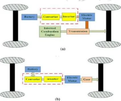
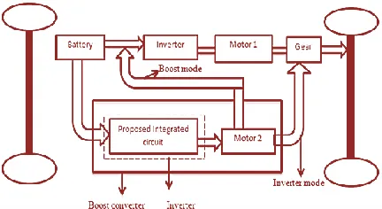
In parallel hybrid electric vehicle (HEV) [1]–[3] andelectric vehicle (EV) [4], [5] system as shown in Fig. 1, theconverter is used for boosting the battery voltage to rated dcbus for an inverter to drive motor. In the multimotor drivesystem [6], [7], the system will use two or more motors toboost torque, especially under low speed and high-torqueregion as shown in Fig. 2. For such applications, two or moreinverters/converters are required. Fig. 3 shows theapplication of the proposed integrated circuit for motordrives with dual-mode control for EV/HEV
applications. Asshown in Fig. 3, the proposed integrated circuit allows thepermanent magnet synchronous motor (PMSM) to operate inmotor mode or acts as boost inductors of the boost converterand thereby, boosting the output torque coupled to the sametransmission system or dc-link voltage of an inverterconnected to the output of the integrated circuit.
Figure 1: HEV and EV system (a) Parallel HEV drive train.(b) EV drive train.
Figure 3: Proposed integrated inverter/converter for themulti motor drive system
In motormode, the proposed integrated circuit acts as an inverter andit becomes a boost-type boost converter, while using themotor windings as the boost inductors to boost the converteroutput voltage. Therefore, the proposed integrated circuit cansignificantly reduce the volume and weight of the system.
II. DFIG Wind Power System
In Figure 4 the block diagram having aproposed integrated circuit for the drive a PMSM, by this circuit to drivean electric motor under dual modes of operation in EV/HEV applications. The proposed integrated circuit hasto permit the permanent magnet synchronous motor (PMSM) to operate in Motoring mode or Boost inductorof the Boost converter mode of two-phase interleaved boost converter. In Boost converter mode, the motorwindings are behaved like an inductor of the boost converter circuit and thereby uplift the dc-link voltage ofthe inverter connected to the output of the integrated circuit or to boost the output torque coupled to the sametransmission system.
Figure 4: Proposed integrated inverter/converter circuit for the multi-motor drive system of EV/HEV
In the motoring mode, the proposed integrated circuit acts as an inverter alone. But, in the converter mode, the proposed integrated circuit becomes a boost type boost converter while the motor windings are just used asa boost inductor of the converter circuit. So, the proposed integrated circuit can noteworthy remit the volumeand weight of the system. The proposed integrated circuit act as an inverter or boost converter
depending uponthe operating modes. It not only can remit the volume and weight of the system and also boost the torque anddc-link voltage of the motor/converter modes.
A. Proposed integrated circuit:
Figure 5 shows the integrated circuit for dual mode control. In Figure 5 Cin and Cout are used to stabilize thevoltage when input and voltage voltages are disturbed by source and load respectively. Diode (D) is used toprevent reverse current attainment and voltage impact on the input side.
Figure 5: Proposed circuit for dual mode of motoring mode and boost converter
In this paper, Figure 5 shows the proposed integrated circuit act as an inverter or boost converterdepending on the operating modes. The conventional boost converter circuits are the most resemblance ofthe single phase boost converter and also widely used for boost control due to its simplicity. However, forhigher power applications the interleaved boost converters are to be preferred.
Specification of Components
Component Specifications
Cin/Cout 330 mF/450V,
Diode
V
R = 500V, Ron = 0.001 W, VF = 0.87V
IGBT
V
CE = 600 V, IC = 75A, VCE(sat) = 1.5V
[5]. Interleaved boostconverter model concepts becomes very powerful. Because, it to keep input currents has manageable andto increase the efficiency and meanwhile it’s maintaining good power density [6]. In the interleaved controlmethod, the boost- control technique using motor windings as a boost inductor for the proposed integratedcircuit.
B. Motoring (Inverter) Mode:
The integrated circuit operate in inverter (motor) mode, the Relay will get turned ON (switch is closed) andsix power devices (IGBT-switch) are to be controlled by the PWM control signal [7]. The three phase load ispermanent magnet synchronous motor. The three-phase AC voltage is supplied from three phase inverter toPMSM by suitably turn ON and OFF the switches with a delay in 120° mode of operation. PMSM get threephase AC voltage with the mechanical input of torque (Tm). To provide the outputs of electromagnetic torque,mechanical speed, and stator current.
Mechanical power P = TwLet, P = 3000 KW, N = 2000 RPM, w = 2pN rad/sec
C. Boost Converter Mode:
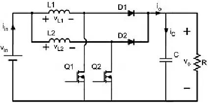
In above Figure 6 shows the two-phase interleaved boost converter, the two converter channels are connectedin parallel combination. Channel-1 is composed of switch Q1, Inductor L1, Diode D1 and channel-2 are alsocomposed by the same of Q2, L2, and D2. The Filter capacitor C is shared by the two channels commonly atthe output. Whereas, the two channels are connected in parallel but operate in an interleaved mode. With theinterleaving design, the gating signals for switch Q1 and Q2 are identical but shifted by 360°/2 = 180°. Here,the 2 is the no of converter connected in parallel [5].
Figure 6: two phase interleaved boost converter
When the proposed integrated circuit is operated in the converter mode, the relay is get turned OFF (switchis open) and single or two-phase interleaved control is applied to control power devices depending upon the loadconditions. Two phase interleaved boost converter uses the power switches of V* and W*, the stator windingof A, B and C for boosting the voltage and reduce the current ripple [7].
III. SIMULATION AND RESULTS
Here the simulation carried by two different cases they are 1)Proposed interleaved boost converter multiplier module 2)PV as input source of proposed converter with interleavedboost converterCase-1 Proposed interleaved boost converter
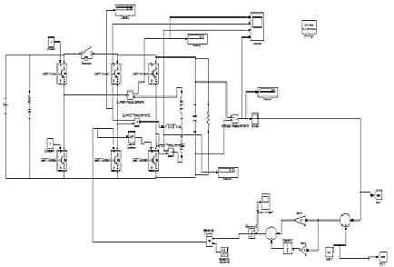
Figure 7 Matlab/simulinkmodel of the integrated circuitand controller
Figure 8: measured current with and without interleavedcontrol, Single-phase interleaved boost
Figure 9: Measured current with and without interleavedcontrol, Two-phase interleaved boost
converters
Figure 10: simulated waveforms for the transition betweensingle-phase control and two-phase interleaved control fromtwo-phase interleaved to
single-phase modes.
Figure 11: simulated waveforms for the transition betweensingle-phase control and two-phase interleaved controlsingle-phase to two-phase
interleaved modes
Figure 12: Matlab/Simulink model of the proposed singlephase converter with closed loop operation
Figure 13: Simulated output wave forms of the closedloop control of the single phase converter with
referencevalue 324V
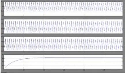
Figure 15: Simulated output wave forms of the closedloop control of the Two phase interleaved
converter withreference value 324V
IV. CONCLUSION
In this proposal of a new integrated inverter/converter circuit ofmotor drives with dual-mode control for EV/HEVapplications to significantly reduce the volume and weight. However the proposal of a new control method for the integratedinverter/ converter circuit operating in boost converter mode to increase the efficiency also verification of the proposed integrated inverter/converter circuit. Verification of the proposed control method. Experimentalresults show that the voltage boost ratio can go up to 3.Under full-load condition, the maximum efficiency is morethan 96% and efficiency can be maintained at morethan91.9% for voltage ratios varies from 1.25 to 3.
REFERENCES
[1] M. Habib Ullah, T. S. Gunawan, M. R. Sharif, and R. Muhida, “Designof environmental friendly hybrid electric vehicle,” in Proc. IEEE Conf.Comput. Commun. Eng., Jul. 2012, pp. 544–548.
[2] O. Hegazy, J. Van Mierlo, and P. Lataire, “Analysis, modeling, and implementation of a multidevice interleaved DC/DC converter for fuel cellhybrid electric vehicles,” IEEE Trans. Power Electron., vol. 27, no. 11,pp. 4445–4458, Nov. 2012.
[3] W. Qian, H. Cha, F. Z. Peng, and L. M. Tolbert, “55-kW Variable 3X DCDC Converter for plug-in hybrid electric vehicles,” IEEE Trans. PowerElectron., vol. 27, no. 4, pp. 1668–1678, Apr. 2012.
[4] M. Yilmaz and P. T. Krein, “Review of battery charger topologies, charging power levels, and infrastructure for plug-in electric and hybrid vehicles,” IEEE Trans. Power Electron., vol. 28, no. 5, pp. 2151–2169, May2013.
[5] G. Maggetto and J. Van Mierlo, “Electric and electric hybrid vehicletechnology: A survey,” in Proc. IEE Semin. Electric, Hybrid Fuel CellVehicles, Apr. 2000, pp. 1–1-111.
[6] J. Zhang, X. H. Wen, and L. Zeng, “Optimal system efficiency operation ofdual PMSM motor drive for fuel cell vehicles propulsion,” in Proc. IEEEInt. Power Electron. Motion Control Conf., May. 2009, pp. 1889–1892.
[7] J. Zhang, X. H. Wen, and Y. L. Wang, “Research on optimized control technique of electrical vehicles propulsion system with dual PMSMconnection,” in Proc. IEEE Energy Convers. Congr. Expo., Sep. 2011,pp. 1708–1712.
[8] Y. S. Lai, C. A. Yeh, and K. M. Ho, “A family of predictive digitalcontrolled PFC under boundary current mode control,” IEEE Trans. Ind.Informatics, vol. 8, no. 3, pp. 448–458, Aug. 2012.
[9] Y. Jang, G. Feng, and M. M. Jovanovic, “Interleaved boost bonverterwith Intrinsic voltage-doubler characteristic for universal-line PFC frontend,” IEEE Trans. Power Electron., vol. 22, no. 4, pp. 1394–1401, Jul.2007.
[10] M. A. P. Andrade, L. Schuch, and J. R. Pinheiro, “Generalized switchinglogic scheme for CCM-PFC interleaved boost converters,” in Proc. IEEEPower Electron. Spec. Conf., 2004, pp. 2353–2359.
[11] Y. Gu and D. Zhang, “Interleaved boost converter with ripple cancellationnetwork,” IEEE Trans. Power Electron., vol. 28, no. 8, pp. 3860– 3869,Aug. 2013.
[13] T. Grote, H. Figge, N. Frohleke, W. Beulen, F. Schafmeister, P. Ide, and ¨J. Bocker, “Semi-digital interleaved PFC control with optimized light load ¨efficiency,” in Proc. IEEE Appl. Power Electron. Conf. , 2009, pp. 1722–1727.
[14] R. W. Erickson and D. Maksimovic, ´ Fundamental of Power Electronics,2nd ed. Norwell, MA, USA: Kluwer, 2001.