Comparison of Nth Harmonic Injection
Technique with SPWM Technique for
N-Phase VSI Fed N-Phase IM Drive
R. Venkateswarlu1, C.Prashanth2, M.Vijaya Kumar3
PG Student [PID], Dept. of EEE, JNTUA College of Engineering, Anantapuramu, Andhra Pradesh, India1 Lecturer, Dept. of EEE, JNTUA College of Engineering, Anantapuramu, Andhra Pradesh, India2 Professor, Dept. of EEE, JNTUA College of Engineering, Anantapuramu, Andhra Pradesh, India3
ABSTRACT: This paper presents modeling of multiphase IM and modeling of multiphase inverter with SPWM and nth harmonic injection methods. In general the machine with phase number greater than three possess several advantages such as less torque ripple, fault tolerant capability, phase redundancy, high torque density, less current ripple, greater efficiency and high stability. There is a possibility to increase the power/torque per RMS current for the machine with phase number more than three for same volume of the machine. To provide a sufficient output voltage to a multiphase induction machine, it is necessary to implement suitable switching schemes for multi-phase inverters. The schemes namely SPWM and nth harmonic injections are discussed. The performance of the inverter with these switching techniques analyzed for different phase number like 3, 5, 7, 9 and 11 etc. and notices that nth harmonic injection method give better results than SPWM. Finally a detailed d-q modeling of multi-phase IM drive with nth harmonic injection method based multiphase VSI is developed. The VSI fed multiphase drive is analyzed in terms of stator current, torque and speed for different phases. The simulation output results are shown for 3, 5, 7, 9 and 11 phase IM drive under varying different step load conditions.
KEYWORDS:d-q axes model, SPWM, Nth harmonic injection, multiphase drive, IM (induction motor), VSI.
I.INTRODUCTION
The three phase machines are mostly used as variable-speed electrical drives. As compared to normal three phase induction machines, the high phase order machines possess the following advantages greater efficiency and reliability, increased fault tolerance, less torque ripple; Higher torque density ,enhanced modularity and Less power/phase handling capability requirements; reduced noise characteristic etc.The multiphase machines are used in several applications such as hybrid/electrical vehicles, ship propulsion, high power and aerospace applications, here a leg of the drive can be formed by using several solid state devices. Recently, the high phase order system applications include greater torque brush less low speed machines are applied to electric vehicle applications, For ship propulsion we are using permanent magnet motor drives, permanent motor with less torque ripple and a single phase inverter supplied series connected two motor drives in [1-2].To develop the general model of a high phase order Induction machine we use the mathematical representation of an Induction machine in terms of arbitrary number of phases on both rotor and stator side can be implemented by using general theory of electrical machines. The HPO induction machine can be designed with sinusoidal distributed winding or with concentric winding. The modelling is available at general level in [3]. To develop a general model, winding displacement is taken into consideration. It is not necessary the winding displacement is symmetrical. The derived voltage equations in phase variable form and dqo axes transformation of unsymmetrical displacement windings of a multiphase induction machines has been reported in[4-6].
efficient and simple switching technique for multiphase VSIs for their switching process. Since a improved PWM technique is called nth harmonic injection method. It is used to avoid complexity involved in higher number of phases. In these paper a detailed study of SPWM and nth harmonic injection method is carried out and find out that nth harmonic method give better THD when compare to SPWM method. In the nth harmonic method linear modulation range is extended to beyond one by adding nth harmonic component to the respective reference phase voltage due to these fundamental voltage increases without moving into the over modulation range[13-15].
II. LITERATURE SURVEY
BimalK.Bose,ELevi [1-2] presents the multiphase machines are used in several applications such as hybrid/electrical vehicles, ship propulsion, high power and aerospace applications, here a leg of the drive can be formed by using several solid state devices. Recently, the high phase order system applications include greater torque brush less low speed machines are applied to electric vehicle applications, For ship propulsion we are using permanent magnet motor drives, permanent motor with less torque ripple and a single phase inverter supplied series connected two motor drives.
E.Levi,R.Bojoi,F [3] discuss about the development of the general model of a high phase order Induction machine we use the mathematical representation of an Induction machine in terms of arbitrary number of phases on both rotor and stator side can be implemented by using general theory of electrical machines. The HPO induction machine can be designed with sinusoidal distributed winding or with concentric winding.
III.D-QMODEL OF MULTIPHASE IMDRIVE
The physical multiphase machine can be transformed by using mathematical transformation. The condition while transforming original machine model is that, before and after transformation the number of variables must be remain same. This means that m-phase will have m- new stator voltages, stator currents and stator fluxes after transformation
also. The space displacement between any two successive stator phases is α=2π/n. since it is assumed that higher space
harmonics are neglected and also windings are distributed sinusoidally, and also assume that the windings are connected in star with single neutral point regard less of the number of phases. The original machine model can be transformed to n-new set of variables by using clarke’s decoupling transformation matrix, and rotational transformation matrix is applied to first two rows of the clarke’s transformation matrix because the last two rows are zero sequence components , its does not exist in any star connected windings with single neutral point for odd number of phases. Zero sequence component will exit in only even number of multiphase machines, So that the last two rows are not contributed for the fundamental torque production. First two rows only takes place to produce fundamental torque and flux and also stator to rotor coupling takes place only in these two rows that’s why remain rows and zero sequence component rows neglected while applying rotational transformation. Due to stator and rotor coupling does not takes place in these set of rows. Finally the rotational transformation can be applied to those α-β equations only. The machine
equations finally transform to arbitrary reference frame with we as rotational speed.
⎣ ⎢ ⎢ ⎢ ⎢ ⎢ ⎢ ⎡ . . 0 0 ⎦ ⎥ ⎥ ⎥ ⎥ ⎥ ⎥ ⎤ =√ ⎣ ⎢ ⎢ ⎢ ⎢ ⎢ ⎢ ⎢
⎡ 1 cos cos 2 cos 3 . . cos( −1)
0 sin sin 2 sin 3 . . sin( −1) 1 cos 2 cos 4 cos 6 . . cos 2( −1) 0 sin 2 sin 4 sin 6 . . sin 2( −1)
. . . .
. . . .
1/√2 1/√2 1/√2 1/√2 . . 1/√2 1/√2 −1/√2 1/√2 −1/√2 . . −1/√2 ⎦
⎥ ⎥ ⎥ ⎥ ⎥ ⎥ ⎥ ⎤ ⎣ ⎢ ⎢ ⎢ ⎢ ⎢ ⎢ ⎡ . . ⎦ ⎥ ⎥ ⎥ ⎥ ⎥ ⎥ ⎤ (1)
Stator Circuit equations
Voltage Equations
= + + (2)
= − +
(3)
Flux linkage Equations
= ( + ) +
(5)
Current Equations
=
( )( )
(6)
=
( )( )
(7)
Rotor circuit Equations Voltage Equations
= + ( − ) + (8)
= −( − ) + (9)
Flux linkage Equations
= ( + ) + (10)
= ( + ) + (11)
Current Equations
=
( )( ) (12)
=
( )( ) (13)
Where the symbols L and R stands for inductance and resistance, while the indices r, s and l identify the rotor, stator and leakage inductances respectively. V, i, Ls, Lr, Lmand ψ denote voltage, current, stator self-inductance, rotor
self-inductance magnetizing self-inductance, and flux linkages respectively.
The torque and speed equation is given with Lm = (n/2)*M and where M is the mutual inductances between rotor to
stator in the phase variable model. Torque equation is given with
= ( − ) (14)
=∫ ( ) (15)
IV. GENERALIZED SPWM AND NTH HARMONIC INJECTION METHOD FOR MULTIPHASE VSI
SPWM is a carried based PWM technique. It is widely used and most popular PWM technique method, due to their simple implementation [9]. It is used for three phases and also applicable to multi-phase VSI. In these method sinusoidal signal compared with the carrier (triangular or saw tooth) signal. The carrier signal frequency is normally kept much greater than the normal reference sinusoidal signal. In this n- sinusoidal fundamental signals can be
displaced by α=2π/n in time. Where α=2π/n; n= number of phases. The inverter pole voltages are Va, Vb, Vc, Vd,
….Vnare connected to load terminals of induction motor. The dc voltage to inverter is given by single or three phase
ups through rectifier. These N- leg reference voltages are connected to N-phase induction motor drive. In SPWM method MISPWM=1 maximum in linear mode region..Modulation index= fundamental output voltage of inverter/dc link
Fig.1. power circuit of multiphase VSI
In N-phase VSI for eliminating Nth harmonic component we need to inject Nth harmonic component to the sinusoidal reference voltages [15]. By adding Nth harmonic component to the reference sinusoidal signal the fundamental component is increases without entering into the over modulation region. There is no effect on the phase output voltages by adding Nth harmonic component, since load is star connected and neutral is isolated. Therefore Nth harmonic injection method reduces peak value of the N-leg reference voltages due to these modulation index goes greater than one without entering over modulation. According to Nth harmonic injection method, there are two modulation indexes, one is modulation index of fundamental (MI) and another one is modulation index of Nth harmonic component (Mn).
Fig.2. mthharmonic injection method
( )= [ + ] (16)
( ) = [ cos( − ) + cos ] (17)
( ) = [ cos( −2 ) + cos ] (18)
( )= [ cos( − ) + cos ] (19)
The values of MI and Mn according to nth harmonic method are given by following equations
MI=1/cos(π/2n) (20)
Mn= -MI sin(π/2n)/n (21)
V. SIMULATIONRESULTS
fundamental reference frequency is kept at 50Hz. The modulation index M is set to 1 for SPWM method and
modulation index M=1/cos(π/2n) for Nth harmonic injection method. Fig.3 shows the SPWM results of carrier, phase voltage and its spectrum for five phase VSI with MI=1. Fig 4 and 5 shows the Nth harmonic injection results of carrier, phase voltage and its spectrum for five phase VSI with modulation index’s of 1 and 1.0515 respectively. It is seen that the peak value of modulating signal is less than 1 in case of Nth harmonic injection method with MI=1.. It will reach
one when the modulation index M=1/cos(π/2n), according to equation (20). So that the maximum fundamental voltage
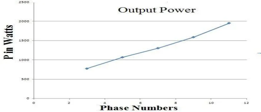
increases without moving into over modulation region with Nth harmonic method. The THD is also reduces and the THD comparisons of SPWM and Nth harmonic injection methods are shown in table 1 and corresponding results are shown in fig.11 and fig.12. The steady state analysis for different phase numbers are presented in table 2 and corresponding output power also shown in fig.13. When phase number increases output power also increases mentioned in figure13.Fig.6 to fig.10. Shows the inverter fed IM drive simulation results for 3,5,7,9 and 11 phases under varying different load conditions. The torque load is varied in steps as 0%, 25%, 50%, 75% and full load at every 0.5sec respectively. Where 0% is indicate that motor is loaded at no load. From the simulation results we observe that stator current is increases along with the load. Speed decreases along with the load and the motor torque follows the load torque in steps at every 0.5 sec.
(a) Carrier signal is compared with the modulating signal of five phase IM drive for MI=1(SPWM).
(b) Output voltage of five phase VSI with SPWM Method for MI=1.
(c) Phase voltage spectrum of five phase VSI in SPWM Method for MI=1.
(a) Carrier signal is compared with the modulating signal of five phase IM drive for MI=1(Harmonic method).
(b) Output voltage of five phase VSI with Nth harmonic injection method for MI=1.
(c) ) Phase voltage spectrum of five phase VSI in Nth harmonic injection Method for MI=1
Fig.4. Nth harmonic injection with MI=1 (a) carrier signal compared with modulating signals (b) phase voltage (c) phase voltage spectrum.
(b)Output voltage of five phase VSI with Nth harmonic injection method for MI=1.0515.
(c)) Phase voltage spectrum of five phase VSI in Nth harmonic injection Method for MI=1.0515.
Fig.5. Nth harmonic injection with MI=1.0515 (a) carrier signal compared with modulating signals (b) phase voltage (c) phase voltage spectrum.
The following diagrams represent the output results of three phase IM drive at different load conditions. .
The following diagram represents the simulation results of five and seven phase induction motors at different loads.
Fig.7. Simulation results of 5 phases VSI fed IM drive with different load conditions.
Fig.8. Simulation results of 7 phases VSI fed IM drive with different load conditions.
The following diagrams represent the output results of nine and eleven phase IM drive at different loads.
Fig.10. Simulation results for 11-phase VSI fed IM drive with different load conditions
Table I: THD Comparison of SPWM and Nth harmonic injection methods for different phases.
MI 3-PHASE 5-PHASE 7-PHASE 9-PHASE 11-PHASE
SPWM THD
HARMONIC THD
SPWM THD
HARMONIC THD
SPWM THD
HARMONIC THD
SPWM THD
HARMONIC THD
SPWM THD
HARMONIC THD
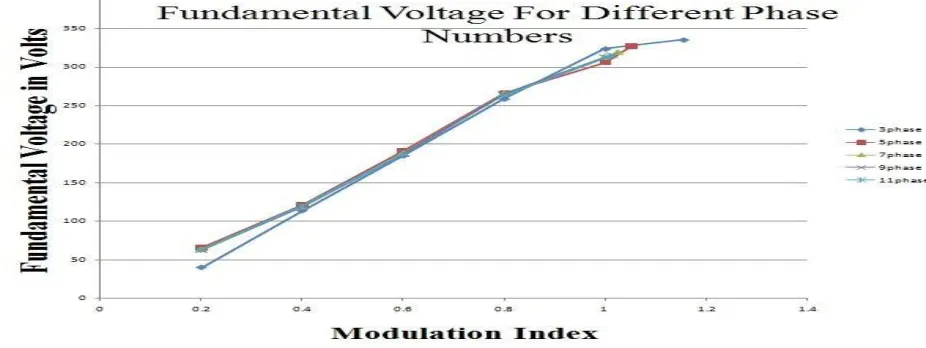
0.2 331.5 247.67 259.76 254.36 268.66 259.54 269.64 262.8 270.24 265.99
0.4 201.55 173.13 174.95 173.33 174.26 176.73 174.89 177.32 175.23 178.31
0.6 138.9 122.81 126.15 124.29 129.29 127.78 130.06 128.89 130.38 129.68
0.85 83.63 87.70 91.70 91.15 93.39 92.82 94.08 93.89 94.35 94.48
1 72.35 63.82 78.85 76.77 77.37 76.08 78.08 77.36 78.39 77.57
1.1547 60.12
1.0515 69.78
1.0257 74.12
1.0154 76.16
1.0103 76.92
The following graph represents the relationship between MI and Fundamental voltage of multiphase VSIs .
The following graph represents the relationship between MI and THD of multiphase VSIs.
Fig.12. THD verses modulation index for different phases.
Table II. Steady state analysis for different phase numbers under rated load conditions.
NO OF PHASES 3 5 7 9 11
MI 1 1 1 1 1
VL 220 220 220 220 220
RATED TORQUE(TL) 5 8.83 11.66 15 18.33
NR 1193 1198 1204 1207 1209
IS/PHASE 2.03 2.17 2.24 2.41 2.68
POWER IN WATTS
773.51 1067.5 1303.8 1590.6 1955.48
The following graph represents the relationship between Phase number and power in watts of multiphase IM drive.
VI.CONCLUSION
This paper address the generalized model of multiphase VSI fed multiphase IM drive developed under MATLAB/Simulink. It is developed using the basic built in blocks of Simulink following the corresponding equations. It is tested for different phase number at different loading conditions. In case of VSI switching techniques SPWM and Nth harmonic injection methods are observed and we go for Nth harmonic injection method because of their reduced complexity in case of higher number of phases and better THD when compared to SPWM. Also this would increase the max fundamental voltage without entering over modulation region. the simulation results are obtained for 3,5,7,9 and 11 phases. For future work offset injection switching technique method is used for multiphase VSI for better maximum fundamental voltage and also better performance of multiphase VSI fed multiphase IM drives for different phases under different load conditions.
REFERENCES
[1]BIMALK.BOSE,MODERN POWER ELECTRONICS AND AC DRIVES,PRENTICE HALL 2002.
[2]ELevi, "Multiphase Electric Machines for Variable Speed Applications," IEEE Transactions on Industrial Electronics, vol. 55, no. 5, pp. 1893- 1909, MAY2008.
[3 ]E.Levi,R.Bojoi,F.Profumo,H.A.Toliyat and S.williamson, “Multiphase induction motor drives-A technology status review,” IETElect. Power Appl. vol. 1, no. 4, pp. 489-516,July 2007.
[4] E.E. Ward and H.Harer, “Preliminary investigation of an inverter fed five-phase induction motor”, Proc. IEE 116 (6), , pp.980- 984,1969. [5] T.M. Jahns, “Improved reliability in solid-state AC drives by means of multiple independent phase-drive units”, IEEETransactions on Industry Applications,vol. IA-16, no. 3, , pp. 321-331,may.-jun.1980.
[6] G.Renukadevi and K.Rajambal, “Generalized Model of Multi-Phase Induction Motor Drive using Matlab/Simulink,” International IEEEPES Conference Innovative Smart GridTechnologies,Kerala-India, 2011.
[7] G.D.Holmes, T.A.Lipo, "Pulse Width Modulation for Power Converters - Principles and Practice," IEEE Press Series on Power Engineering, John Wileyand Sons, Piscataway, NJ, USA, 2003.
[8]Kelly, J.W., Strangas, EG., and Miller, J.M.: 'Multi-phase inverter analyses. Proc. IEEE Int. Electric Machines and Drives Conf. IEMDC, Cambridge ,pp. 147-155,2001
[9]G.Renukadevi and K.Rajambal, "Novel Carrier-Based PWM technique for n-Phase VSI," International Journal of Energy Technologies and Policy,pp. 1-9,2011.
[10]A.Iqbal, ELevi, "Space vector modulation scheme for a five-phase voltage source inverter," Proc. European Power Electronics (EPE) Con!,Dresden,Germany, CD-ROM paper no. 0006.pdf,2005.
[11]J.W.Kelly, E.G.Strangas, J.M.Miller, "Multi-phase space vector pulse width modulation," IEEE Trans. on Energy Conversion, vol. 18, no. 2, pp. 259-264,2003.[12]Zhou K and Wang D, "Relationship between Space vector modulation and Three-phase carrier based PWM - A comprehensive analysis", IEEE
Trans. Ind.Electron.,49,( 1) ,pp 186-196,2002.
[13]G.Renukadevi and K.Rajambal, "Performance Investigation of Multi-Phase VSI with Simple PWM Switching Techniques," International journalof Engineering,vol. 26, No. 1,pp.451-458, March-20I3.
[14] G.Renukadevi and K.Rajambal, "Comparison of Different PWM Schemes for n-Phase VST," International Conference on Advances In Engineering, Science And Management (ICAESM -2012) M, pp.559-564,arch 30, 31,2012.