B. Pujita , S K.Sahir
Novel Correction and Detection for
Memory Applications
1
B.Pujita , 2SK.Sahir
1M.Tech Research Scholar, Priyadarshini Institute of Technology & Science, Chintalapudi, India
2HOD, Priyadarshini Institute of Technology & Science, Chintalapudi, India
Abstract:
As a result of technology scaling and higher integration densities there may be variations in parameters and noise levels which will lead to larger error rates at various levels of the computations. As far as memory applications are concerned the soft errors and single event upsets are always a matter of problem. The paper mainly focuses on the design of an efficient Multi
Detector/Decoder (MLDD) for fault
detection along with correction of fault for memory applications, by considerably reducing fault detection time. The error detection and correction method is done by one step majority logic decoding and is made effective for Euclidean Geometry Low Density Parity Check Codes (EG-LDPC). Even though majority decodable codes can correct large number of errors, they need
high decoding time for detection of errors and ML Decoding method may take same fault detecting time for both erroneous and error free code words, which in turn delays the memory performance. The proposed fault-detection method can detect the fault in less decoding cycles (almost in three). When the data read is error free, it can obviously reduce memory access time. The technique keeps the area overhead minimal and power consumption low for large code word sizes.
Keywords:
One step majority logic decoding; error
correction codes (ECCs); Euclidean
geometry low-density parity check (EG- LDPC); memory; control logic.
1. INTRODUCTION
Memories are the most universal component today. For more than a decade, memory cells have been protected from soft errors. Some type of embedded memory, such as ROM, SRAM, DRAM, flash memory etc is seen in almost all system chips. Now days, the memory failure rates are increasing due to
memory parts of the system and to choose the correct data using a voter. This method have disadvantage of large area and complexity overhead of three times. Therefore the ECC became the best way to
mitigate soft errors in memory
[4].Dr.M.Jagadeeswari M.E VLSI DESIGN Sri
Ramakrishna Engineering College
Coimbatore, India
The most commonly used ECC codes are Single Error Correction (SEC) codes that can correct one bit error in a memory word. Due to consequence of augmenting integration densities, there is an increase in soft errors which points the need for higher error correction capabilities [1], [3]. More advanced ECCs have been proposed for memory applications but even Double Error Correction (DEC) codes with a parallel implementation incur in a significant power consumption penalty. The usual multierror correction codes, such as Reed- Solomon (RS) or Bose Chaudhuri-Hocquenghem (BCH) are not suitable for this task due to complex decoding algorithm.
Cyclic block codes have the property of being majority logic (ML) decodable. Therefore cyclic block codes have been identified as more suitable among the ECC codes that meet the requirements of higher error correction capability and low decoding complexity. Euclidean geometry low-density parity check (EG-LDPC) codes, a subgroup of the low-density parity check (LDPC) codes, which belongs to the family of the ML
decodable codes, is focused here.
The advantages of ML decoding are that it is very simple to implement and thus it is very practical and has low complexity. The drawback of ML decoding is that, it needs as many cycles as the number of bits in the input signal, which is also the number of taps, N, in the decoder and also same decoding time for both error and error free code words. This is a great impact on the performance of the system, depending on the size of the code.
Another alternative is to first detect if there are errors in the word and only perform the rest of the decoding process when there are errors. This greatly reduces the average power consumption as most words will have no errors. Error detection in a block code can also be implemented by computing the syndrome and checking whether all its bits are zero [15]. By calculating the syndrome, we can implement a fault detector for an ECC is but this also would add an additional complex functional unit. This paper focus on using the MLD circuitry itself as an error detecting module therefore with no additional hardware the read operations could be accelerated.
B. Pujita , S K.Sahir
Finally, Section V discusses conclusions and future work.
II. MAJORITY LOGIC DECODING
(MLD) SOLUTONS
One-step majority-logic correction is a fast and relatively efficient error-correcting technique [6]. One-step-majority correctable ECC codes are limited which include type-I two-dimensional EG-LDPC.
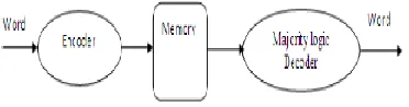
Fig 1.Memory system Schematic
The memory system schematic shown in Figure 1 show that the word is first encoded and is then written to the memory [2]. After the reading process of the memory it is passed to a majority logic detector block which detects and corrects the errors which occurred while the reading code word.
Figure 2: Existed plain ML decoder
This type of decoder can be implemented in two ways. The first one is called the Type-I ML decoder, which determines the bits need to be corrected from the XOR combinations of the syndrome, [9]. The Type-II ML decoder that calculates the information of correctness of the current bit under decoding, directly out of the codeword bits [6]. Both are quite similar, but when implementation is considered the Type-II uses less area, since it does not have a syndrome calculation as an intermediate step. For this reason the paper focus on this type II implementation.
A. Existent Plain ML Decoder
Step Majority-Logic Corrector: One-step majority logic correction is the process in which from the received codeword itself the correct values of each bit under decoding can directly found out. This method consists of mainly two steps- 1) Generating a specific set of linear sums of the received vector bits using the xor matrix 2) Determining the majority value of the computed linear sums. It is the majority logic output which determines the correctness of the bit under decoding. If the majority output is '1', then the bit is inverted, otherwise would be kept unchanged.
the codeword bit under decoding. The circuit implementing a serial one-step majority logic corrector [6], [12] for (15, 7, 5) EG-LDPC code is shown in Figure 2.
The cyclic shift register is initially stored with the input signal x and shifted through all the taps. The results {Bj} of the check sum equations from the XOR matrix is calculated from the intermediate values in each tap. In the Nth cycle, the result would reach the final tap, producing the output signal, which is the decoded version of input [2].Figure 2. Serial one-step majority logic corrector for (15, 7, 5) EG-LDPC code This is the situation of error free case. The input x might correspond to wrong data corrupted by a soft error or SEUs. The decoder is designed to handle this situation as follows.
From the parity check sum equations hardwired in the xor matrix the decoding starts at the very next moment after the codeword x are loaded into the cyclic shift register. The linear sum outputs {Bj} is then forwarded to the majority logic circuit which determines the correctness of the bit under decoding. If the majority of the Bj bits are "1" that is greater than the majority number of zeros then the current bit is erroneous and should be corrected, otherwise it is kept unchanged.
The process is repeated and contents of the shift registers are rotated up to the whole N bits of the codeword are processed. When all the parity check sums outputs are zero the codeword is correctly decoded. Further details on how this algorithm works can be found in [6], [12]. The whole
algorithm [2] is depicted in Figure 3. The algorithm needs as many cycles as the number of bits in the input signal, which is number of taps, N, in the decoder and also needs same decoding time for both error and error free code words.
III.
PROPOSED
MULTI-
DETECTOR/DECODER
A novel version of the MD decoder for improving performance is presented here. With reference to the original ML decoder, the proposed MD detector/decoder (MDD) has been implemented using the Hamming and parity check (HMPC) and general decoder. This proposed design uses much more easy way implementation for detecting and correcting.
The proof of the hypothesis that all error will be detected in eight cycles is very simple from the mathematical point of view. It is practical to generate and check all possible error combinations for codes with small words and affected by a small number of bit flips. When the size of code and the number of bit flips increases, it is difficult to exhaustively test all possible combinations. Therefore the simulations are done in two
ways, the error combinations are
exhaustively checked when it is feasible and in the rest of the cases the combinations are checked randomly.
A. Design structure of the encoder
B. Pujita , S K.Sahir
randomly checking the memory but in this case we have considered a generalized encoder (3:8 or convolution encoder) which can encode the data (as shown in figure). As per the corrector we have the hamming parity check where each code data is divided into sub sectors which enables to check the parity based on the division and then compared to its original value. Considering the original value will equal to the expected corrected value results in correction successfully.
B. Design Structure of Decoder
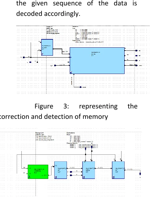
The decoder and detector structure have been shown in the figure. The decoder design is a complex design based on the (BCH decoder/Hamming decoder) which comprises of the received signal and error position from the detector. So hence based on the
position and no of the errors found in the given sequence of the data is decoded accordingly.
Figure 3: representing the
correction and detection of memory
Figure 4: Representing the encoding and decoding of the memory.
Simulation Results:
Technique Total Power Consumption
Proposed MDDD 30mW
Existing MLD 49 mW
B. Pujita , S K.Sahir
IV CONCLUSIONS:
The paper focuses on the design of a Multi Decoder/Detector (MDD) for fault detection along with correction of fault, suitable for memory applications, with reduced fault detection time. From the simulation results, (A codeword of size 8 is chosen here for designing), when compared to the existing
REFERENCES:
[1] S.Lin and D.J.Costello, Error control
coding,2nd ed. Englewood Cliffs, NJ: Prentice-
Hall,2004.
[2] I. S. Reed, ―A class of multiple-error-correcting codes and the decoding scheme, IRE Trans. Inf. Theory, vol. IT-4, pp. 38–49, 1954.
[3] J. L. Massey, Threshold Decoding. Cambridge,MA: MIT Press, 1963.
[4] Y. Kato and T. Morita, ―Error correction circuit using difference-set cyclic code, in Proc. ASP-DAC, 2003, pp. 585–586.
[5] T. Kuroda, M. Takada, T. Isobe, and O. Yamada,―Transmission scheme of high capacity FM multiplex broadcasting system, IEEE Trans.Broadcasting, vol. 42, no. 3, pp. 245–250, Sep.
1996.
[6] O. Yamada, ―Development of an error-correction method for data packet multiplexed with TV signals,‖ IEEE Trans. Commun., vol. COM-35,no. 1, pp. 21–31, Jan. 1987.
[7] H. Naeimi and A. DeHon, ―Fault secure encoder and decoder for NanoMemory applications,IEEE Trans. Very Large Scale Integr. (VLSI) Syst., vol. 17, no. 4, pp. 473– 486, Apr. 2009.
[8] S. Lin and D. J. Costello, Error Control Coding,2nd ed. Englewood Cliffs, NJ: Prentice-Hall,
2004.