An Essential Tree Architecture for Finding
First Two Minima Values and Index
Karnati UmaMaheswari1, R. Lakshman Kumar Reddy2
PG Student [VLSID], Dept. of ECE, GCET, Kadapa, Andhra Pradesh, India1
Assistant Professor, Dept. of ECE, GCET, Kadapa, Andhra Pradesh, India2
ABSTRACT: An Essential tree architecture for finding the primary two minima as well as the index of the first minimum, which is essential in the design of a low-density parity check decoder based on the min–sum algorithm. The proposed architecture reduces the number of comparators by reusing the intermediate comparison results computed for the first minimum in order to collect the candidates of the second minimum. As a result, the proposed tree architecture improves the area–time complexity remarkably.
KEYWORDS: Area-efficient design, digital integrated circuits, low-density parity-check (LDPC) codes, minimum value generation, tree structure.
I.INTRODUCTION
Due to the powerful error-correcting capability, low density parity-check (LDPC) codes have widely been applied to wireless communication systems, personal area networks, and solid-state drives. To eliminate the complicated hyperbolic computations required in the sum–product decoding algorithm, recent LDPC decoders are implemented based on the min–sum (MS) decoding algorithm. In the MS algorithm, the check-node (CN) operation computes the first two minima and the index of the first minimum among many variable-to-check messages given as inputs. Generally, the hardware block that finds the first two minima, which is called a searching module (SM), can be implemented by employing the balanced tree structure. The number of inputs to be compared in selecting the first two minima is increasing to achieve strong and long LDPC codes. For example, a recent SM developed for storage applications deals with more than 100 inputs. The hardware complexity of such a complex SM takes a significant portion in the overall complexity of an LDPC decoder. Moreover, the area taken by multiple SMs becomes more considerable in a high-throughput decoder, as massive CN operations are performed in parallel to increase the decoding throughput.
II. EXISTING SYSTEM
ISSN (Print) : 2320 – 3765 ISSN (Online): 2278 – 8875
I
nternational
J
ournal of
A
dvanced
R
esearch in
E
lectrical,
E
lectronics and
I
nstrumentation
E
ngineering
(An ISO 3297: 2007 Certified Organization) Website: www.ijareeie.com
Vol. 6, Issue 12, December 2017
Fig:1. Flowchart for min-sum algorithm.
Hence a searching module is required in searching the first two minima values and an index. Hence we have many searching modules like tree based and sorting based as discussed below. The algorithm and flowchart for min-sum algorithm is as shown in fig.
For a given set of k w-bit inputs, X = {x0, x1,...,xk−1}, the SM for k inputs produces three outputs: 1) the first minimum value MIN1 = min{X}, 2) the second minimum value, MIN2 = min{X − {MIN1}}, and 3) the index of the
first minimum IDX, which is i if xi is MIN1. Two 2-input primitive units, C1M1 and C1M2, are widely used to realize an SM. As shown in Fig. 2, the C1M1 unit that selects the smaller value from two inputs consists of one comparator and one w-bit 2-to-1 multiplexor. On the other hand, the C1M2 unit is made of one comparator and two w-bit 2-to-1 multiplexors to determine both the larger and smaller values, as depicted in Fig. 3. For the sake of simplicity, we focus in this brief on the generation of MIN1 and MIN2, as IDX can be obtained using the results of comparisons performed for MIN1 [11]. In addition, let the number of inputs k be a power of 2, i.e., k = 2m. When k is not a power of 2, such an SM can be achieved by pruning some leaf nodes of the balanced SM built with 2m inputs where 2m > k, as described.
Fig:3. Detailed structure of generating the index of the first minimum
Fig.3 depicts the conventional sorting-based SM, referred to as SMsort, dealing with eight inputs. The overall process consists of two steps: 1) finding MIN1 with the binary tree structure and 2) selecting MIN2 by means of the multiplexing network controlled by IDX. As shown in Fig.3, IDX can simply be generated from the comparison results, where cij represents the jth comparison result at the ith step of the binary tree. The multiplexing network generates a candidate set of MIN2, Y = {y0, y1, y2}, by employing three 8-to-1 multiplexors. After choosing three candidates, two C1M1 units are used to determine MIN2. As a result, the SMsort necessitates nine comparators, three 8-to-1 multiplexors, and nine 2-to-1 multiplexors to process eight inputs and furthermore suffers from the long critical delay caused by the serially connected structure. Due to the miscellaneous control at the multiplexing network, the critical delay of SMsort is slightly larger than 5TC + 5TM2 + TM8, where TC, TM2, and TM8 stand for the delay of a comparator, a 2-to-1 multiplexor, and an 8-to-1 multiplexor, respectively. For a high-speed realization, the tree-based SM architecture, referred to as SMtree, was proposed in the SMtree designed for eight inputs is exemplified in Fig.4, where the processing times for MIN1 and MIN2 are almost the same as they are both based on the hierarchical tree structure. To calculate exact MIN2 in each subtree, however, SMtree requires more comparators than SMsort. Three C1M1 units and one 2-to-1 multiplexor are additionally used to combine two subtrees, but the serially connected block required for finding MIN2 in SMsort is removed so that the critical delay of SMtree is reduced to 3TC + 5TM2. A faster tree-based SM, denoted as SMradix, was achieved by adopting the mixed-radix scheme]. However, realizing the high-radix computation increases comparators and multiplexors drastically.
Fig:4. Tree based searching module for 8-inputs
ISSN (Print) : 2320 – 3765 ISSN (Online): 2278 – 8875
I
nternational
J
ournal of
A
dvanced
R
esearch in
E
lectrical,
E
lectronics and
I
nstrumentation
E
ngineering
(An ISO 3297: 2007 Certified Organization) Website: www.ijareeie.com
Vol. 6, Issue 12, December 2017
III. IMPLEMENTED SYSTEM
It is possible to reduce the number of comparators needed for the second minimum by reusing the comparison results performed for the first minimum. In the proposed architecture, a candidate set Y for MIN2 is first constructed by using the prior comparison results, and then a comparison network is additionally constructed to select MIN2. This two-step approach is conceptually similar to SMsort, but the second step is much faster in the proposed architecture. As previously discussed, SMsort requires complex multiplexing networks to construct the candidate set and thus suffers from the long critical delay resulting from k-to-1 multiplexors. To eliminate the complex k-to-1 multiplexors, the proposed architecture introduces a basic unit, i.e., PROk, which produces the first minimum of k inputs and m (= log2 k) candidates for the second minimum, as depicted in Fig. 5(a). Similar to SMtree, a PROk unitcan be recursively designed with two smaller PROk/2 units, as shown in Fig. 5(b).
Fig:5. a) Proposed PROk unit, b) Its recursive structure.
The first minimum of k inputs, i.e., MIN1, is simply selected by comparing two minima, i.e., MIN(L) 1 and MIN(R) 1 , produced in PRO(L) k/2 and PRO(R) k/2 units, respectively. Depending on the comparison result of the C1M2, the PROk decides m − 1 candidates for the second minimum by selecting either the candidate set of PRO(L) k/2
or that of PRO(R) k/2. If MIN(L) 1 is smaller than MIN(R) 1 , all the m − 1 candidates of PRO(R) k/2 cannot be the
second minimum, because MIN(R) 1 is the smallest value among the 2m−1 inputs on the right side. Therefore, m
candidates for the second minimum are simply formed by including one of MIN(L) 1 and MIN(R) 1 to the m − 1
Fig:6. Proposed searching module for eight inputs.
ISSN (Print) : 2320 – 3765 ISSN (Online): 2278 – 8875
I
nternational
J
ournal of
A
dvanced
R
esearch in
E
lectrical,
E
lectronics and
I
nstrumentation
E
ngineering
(An ISO 3297: 2007 Certified Organization) Website: www.ijareeie.com
Vol. 6, Issue 12, December 2017
Processing two inputs is identical to the C1M2 unit shown in Fig. 5(b). The major point of the PROk is that the candidate set for the second minimum is constructed in parallel with the searching for the first minimum. After finding the first minimum, another tree structure that can be built with m − 1 C1M1 units is used to find MIN2 among
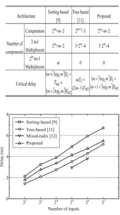
m candidates. Fig. 6 shows how the proposed SM, referred to as SMpro, is constructed to process eight inputs, where a PRO8 unit is followed by a tree structure composed of two C1M1 units to find MIN2 among the three candidates produced in the PRO8 unit. The SMpro in Fig. 6 requires 9 comparators and 20 2-to-1 multiplexors to process eight inputs, whereas the SMtree in Fig. 4 necessitates 13 comparators and 20 2-to-1 multiplexors for the same number of inputs. The critical delay of SMpro is 5TC + 5TM2, which is much smaller than that of SMsort. Table I compares the hardware complexities and critical delays of three different SM architectures, where the number of inputs is assumed to be a power of 2, k = 2m. As there are m final candidates for MIN2, SMsort and SMpro require 2m + m − 2 comparators
in determining two minima, which is much smaller than that of SMtree.
As the proposed architecture completely removes the 2m-to-1 multiplexors that are table 1 comparisons of searching modules for 2m inputs Fig. 7. Critical delay of searching modules for a range of inputs. inevitable in SMsort, the critical delay of SMpro is much smaller than that of SMsort. Note that the delay of SMpro is quite comparable with that of SMtree, as indicated in Table I. As the number of inputs increases, in addition, the proposed structure becomes more area efficient. If the number of inputs is increased to 64, for example, the proposed architecture eliminates 40% comparators of SMtree, remarkably reducing the hardware complexity.
IV. SIMULATION RESULTS
For fair comparison, four types of SMs with a computational bit width of 8 bits are designed and synthesized in a 130-nm CMOS process: the sorting-based one, the tree-based one, the mixed-radix one, and the proposed one. Fig. 8 illustrates how the critical delays of the four SMs are affected by the number of inputs. Note that the critical delay of SMsort is always larger than those of the other SMs due to the complex 2m-to-1 multiplexing networks. As the proposed structure requires additional comparison steps to find the second minimum among m candidates, the delay of SMpro is between those of the previous sorting- and tree-based SMs. The tree-based architectures described in are attractive in terms of computational delay, but they necessitate a significant amount of hardware complexity. The proposed architecture leads to an area-efficient SM, as indicated in Fig. 9. When m is 6, which corresponds to 64 inputs, SMpro saves 34%, 33%, and 68% area over SMsort, SMtree, and SMradix, respectively. As a result, the proposed SM improves the AT complexity remarkably, as shown in Fig. 10. When m is 7, for example, the AT complexity of SMtree is 43% larger than that of SMpro.
Fig:9. Simulations results of 8-bit Proposed searching module.
Fig:10. Simulations results of 16-bit Proposed searching module.
Comparisons of Architectures Searching modules:
ADVANTAGES
The detector has exponentially increased computing complexity with constellation size and number.
It reducing the computational complexity.
ISSN (Print) : 2320 – 3765 ISSN (Online): 2278 – 8875
I
nternational
J
ournal of
A
dvanced
R
esearch in
E
lectrical,
E
lectronics and
I
nstrumentation
E
ngineering
(An ISO 3297: 2007 Certified Organization) Website: www.ijareeie.com
Vol. 6, Issue 12, December 2017
APPLICATIONS
Mobile applications.
Computer and cybernetics applications.
Industrial applications.
V. CONCLUSION AND FUTURE SCOPE
CONCLUSION
We have presented a novel tree structure that finds the first two minima among many inputs. In t he proposed structure, the candidates of the second minimum are collected by utilizing the results of comparisons performed for the first minimum. Hence, the proposed structure minimizes the number of comparators, leading to a low-complexity realization. In addition, the second minimum is selected from the candidates by carrying out a few comparison steps. As the proposed structure eliminates the large-sized multiplexing networks, it improves the AT complexity significantly compared to those of the previous state-of-the art SMS.
FUTURE SCOPE
More feasible structures can design using less comparators and multiplexers and may also implement for high bit length. In feature structure minimizes the more number of comparators, leading to a low-complexity realization. In addition with the second minimum is selected from the candidates by carrying out a few comparison steps. As the proposed structure eliminates the large-sized multiplexing networks, it improves the AT complexity significantly compared to those of the previous state-of-theart SMs.
REFFERENCES
[1] IEEE Standard for Local and Metropolitan Area Networks Part 11: Wireless LAN Medium Access Control (MAC) and Physical Layer (PHY) Specifications, IEEE Std. 802.11n-2009, Oct. 2009.
[2] IEEE Standard for Local and Metropolitan Area Networks Part 16: Air Interface for Broadband Wireless Access Systems, IEEE Std. 802.16-2009, May 2009.
[3] IEEE Standard for Local and Metropolitan Area Networks Part 15.3:Wireless Medium Access Control (MAC) and Physical Layer (PHY) Specifications for High Rate Wireless Personal Area Networks (WPANs), IEEE Std. 802.15.3c-2009, Oct. 2009.
[4] J. Kim and W. Sung, “Rate-0.96 LDPC decoding VLSI for soft-decision error correction of NAND Flash memory,” IEEE Trans. Very Large Scale Integr. (VLSI) Syst., vol. 22, no. 5, pp. 1004–1015, May 2014.
[5] J. Kim, D. Lee, and W. Sung, “Performance of rate 0.96 (68254, 65536) EG-LDPC code for NAND Flash memory error correction,” in Proc. IEEE ICC, 2012, pp. 7029–7033.
[6] Y. Sun and J. R. Cavallaro, “VLSI architecture for layered decoding of QC-LDPC codes with high circulant weight,” IEEE Trans. Very Large Scale Integr. (VLSI) Syst., vol. 21, no. 10, pp. 1960–1964,Oct. 2013.
[7] F. Angarita, J. Valls, V. Almenar, and V. Torres, “Reduced-complexity min–sum decoding algorithm for decoding LDPC codes with low errorfloor,” IEEE Trans. Circuits Syst. I, Reg. Papers, vol. 61, no. 7, pp. 2150–2158, Jul. 2014.
[8] Y.-L. Ueng, B.-J. Yang, C.-J. Yang, H.-C. Lee, and J.-D. Yang, “An efficient multi-standard LDPC decoder design using hardware-friendly shuffle decoding,” IEEE Trans. Circuits Syst. I, Reg. Papers, vol. 60, no. 3, pp. 743–756, Mar. 2013.
[9] D.E. Knuth, The Art of Computer Programming, 2nd ed. New York, NY, USA: Addison-Wesley, 1998.
[10] Q. Xie, Z. Chen, X. Peng, and S. Goto, “A sorting-based architecture of finding the first two minimum values for LDPC decoding,” in Proc. IEEE CSPA, 2011, pp. 95–98.
[11] C.-L. Wey, M.-D. Shieh, and S.-Y. Lin, “Algorithms of finding the first two minimum values and their hardware implementation,” IEEE Trans. Circuits Syst. I, Reg. Papers, vol. 55, no. 11, pp. 3430–3437,Dec. 2008.