Optimized Grid Power Injection with
Maximum Power Point Tracking Using
Cascaded SEPIC Converter and Three Phase
Inverter
S.Ravivarman1, T.Samydurai2
Assistant Professor, Dept. of EEE, K.S.Rangasamy College of Technology, Trichencode, Tamilnadu, India 1
PG Student [PED], Dept. of EEE, K.S.Rangasamy College of Technology, Trichencode, Tamilnadu, India2
ABSTRACT: This paper presents modern single switch dc to dc converter modelling and control of a grid connected renewable energy. The system consists of a Photo voltaic cells, a SEPIC DC-DC converter used for Maximum Power Point Tracking (MPPT), a three-phase grid converter. A nonlinear control performance of a three-phase inverter is proposed to recompense unstable load currents. It permits whole control of DC bus voltage, while calculating power flow from the PV cells to the system and guarantying objective sinusoidal grid currents at unity Power factor under varying solar irradiation. Moreover, a sliding mode control system for a SEPIC DC-DC converter is used to extract the MPPT. The proposed control techniques have exposed good performance. The system is validated using the "Power system Block set" simulator under different values of the solar irradiation.
KEYWORDS:Solar array, MPPT, SEPIC converter, Three level inverter, utility GRID.
I.INTRODUCTION
II. MATHEMATICAL MODEL OF A PV MODULE
Basically a PV module consists of many PV cells arranged in series as well as in parallel to meet the terminal requirements such as nominal operating voltage and current in order to meet out the desired power output. Now-a-days large modules with many cells, all connected in series, are quite obvious.
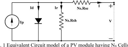
Fig. 1 Equivalent Circuit model of a PV module having NS Cells in Series
The electric circuit model of such a PV module shall be represented by, an ideal current source supplying power in relation to the incident solar radiation, a diode representing the PN junction in the PV cells, a lumped resistance representing the leakage effects, all connected in parallel and one more resistance representing the various effects along the direction of flow of PV current, connected in series with the previously mentioned parallel combination, is shown in the figure (1) [4]. The ivbehaviour of such a PV module described as above can be appropriately modeled analytically and can be represented by a characteristic equation [5] as given in equation (1).
exp s se 1 s se
p OS
s T s sh
V IN R V IN R I I I
nN V N R
(1)where
V Output Voltage of PV Panel I Output Current of PV Panel Ip Light Generated Current IOS Reverse Saturation Current VT Volts Equivalent temperature
Generally the magnitude of Rsh is large enough [9], [10] such that almost for all practical applications the term appears
last in equation (1) can be neglected, and can be reduced to equation (2).
exp s se 1
p OS
s T V IN R I I I
n N V
(2)Under open circuit condition, whereupon the terminal current of the PV module is virtually zero, the equation (2), representing the I-V behaviour of the PV module shall provide the open circuit voltage ‘Voc’ of the PV module as given
by equation (3),
ln p 1
oc s T
os
I V n N V
I
(3)In this technique, the resistance at the MPP is made equal to the incremental resistance at the same point. As the rate of change of PV power with respect to the PV voltage is zero at MPPd P 0
d V and
P
VI
, we shall write the d P d V as followsdP dV dI
I V
dV dV dV (4)
dP dI
I V dV dV
(5)
0
dP
0
dI
I V
dV
(7)I dI
V dV (8) In order to implement this relation using discrete computations, the above equation shall be modified as
I
I
V
V
This is the rudimentary idea behind the incremental conductance technique. Normally the equality rarely occurs [8] therefore a small error factor is incorporated to satisfy the condition.
MPPT Controller
Maximum power point tracking checked by incremental conductance method + Integral regulator. Maximum power point is obtained when dP/dV=0 where P= V*I
d(V*I)/dV = I + V*dI/dV = 0 dI/dV = -I/V
The integral regulator minimizes the error (dI/dV + I/V) Regulator output = Duty cycle correction
SEPIC CONVERTER
The purpose is situated to design and optimize a SEPIC dc/dc converter (Single Ended Primary Inductance Converter). The SEPIC converter allows a range of dc voltage to be adjusted to maintain a constant voltage output. This job talks about the importance of dc-dc converters and why SEPIC converters are used instead of other dc-dc converters. This undertaking also goes into detail about how to control the output of the converter with either a potentiometer or feedback to show how it can be implemented in a circuit. From this project, one learns dc-dc converter optimization and control.Circuits run best with a steady and specific input. Controlling the input to specific sub-circuits is crucial for fulfilling design requirements. AC-AC conversion can be easily done with a transformer; however dc-dc conversion is not as simple. Diodes and voltage bridges are useful for reducing voltage by a set amount, but can be inefficient. Voltage regulators can be used to provide a reference voltage. Additionally, battery voltage decreases as batteries discharge which can cause many problems if there is no voltage control. The most efficient method of regulating voltage through a circuit is with a dc-dc converter. There are five main types of dc-dc converters. Buck converters can only reduce voltage, boost converters can only increase voltage, and buck-boost, Cuk, and SEPIC converters can increase or decrease the voltage.
Some applications of converters only need to buck or boost the voltage and can simply use the corresponding converters. However, sometimes the desired output voltage will be in the range of input voltage. When this is the case, it is usually best to use a converter that can decrease or increase the voltage. Buck-boost converters can be cheaper because they only require a single inductor and a capacitor. However, these converters suffer from a high amount of input current ripple. This ripple can create harmonics; in many applications these harmonics necessitate using a large capacitor or an LC filter. This often makes the buck-boost expensive or inefficient .Another issue that can complicate the usage of buck-boost converters is the fact that they invert the voltage. Cuk converters solve both of these problems by using an extra capacitor and inductor. However, both Cuk and buck-boost converter operation cause large amounts of electrical stress on the components, this can result in device failure or overheating. SEPIC converters solve both of these problems
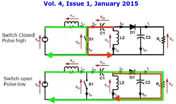
Operation
Fig. 2SEPICConverter operation
Three Phase Voltage Source Inverters
Inverters are commonly used for medium voltage applications. For high-voltage high-power applications, the inverter also serves as a control mechanism for the reactive power and voltage stabilization. With the multilevel converter topology the output waveform can be formed with smaller voltage steps (dv/ dt), which also decreases the stress on the bearings and windingisolation. It obviously also gives a lower total harmonic distortion (THD) in the output, because of the closer resemblance to the sinusoidal waveform. For multilevel converters, medium voltage semiconductors devices can still be utilized for high-voltage high-power applications. Still standing is the issue with the capacitor voltage balancing problems. However, still the multilevel converter dominates on the power electronic platform.
The most studied and tested multilevel types are:
Cascaded H-Bridge Multilevel Converters
Flying Capacitor Multilevel Converters
Diode Clamped Multilevel Converters
For this sector mainly the diode clamped converter will be discussed and studied. The mind behind the inverters switching combination is the pulse width modulation (PWM). There are several different modulation strategies to approach. One of these is the Space Vector Pulse Width Modulation (SVPWM) and will be the theoretical base of this proposition.
Diode Clamped Multilevel Converters
Fig. 3 Three level Diode clamped (neutral point) clamped inverter
Fig.3 shows athree-level inverter needs in a three-phase system 6 diodes. These higher level inverters may work in theory but not in practice. The two diodes clamps the switching voltage to half of the DC-bus voltage and the difference between Va0 (for an example when S1 and S2 is on, the voltage across aand 0 is VDC, giving Va0 = VDC) and Van gives the voltage across one capacitor (VDC/2). It is important to add that the upper and lower switching pairs are complementary.To design a space vector modulated three-level neutral-point diode-clamped converter that can suit any high power application such as the renewable power generation. Mainly because renewable power resources are unreliable and lacks the form of an even output, regulation and adaptation is needed.
III. PROPOSED METHOD OF POWER EXTRACTION AND GRID INJECTION
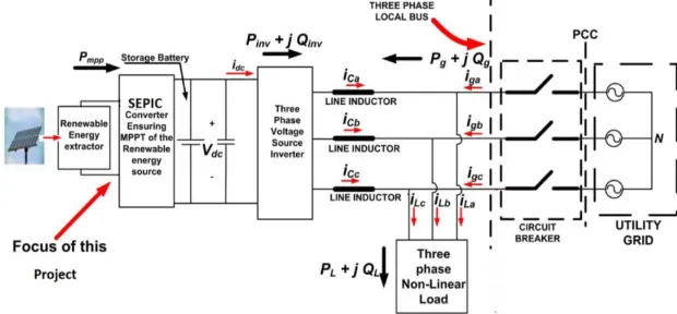
In the proposed method of power extraction from the PV module a SEPIC converter is used which also supplies power as input to the next stage consists of a three phase inverter. The inverter is operated in such a way that the power extracted from the PV module is injected into the grid, also at the same time the level of harmonics, the reactive power compensation and the current balancing are taken care of. The block diagram of the proposed configuration is shown in figure (2). In order to extract the maximum possible power from the PV module, a popular existing MPPT technique of Incremental conductance technique [6], [7] is incorporated in the proposed configuration. These dc-dc converters are regulated by the conventional PWM method at constant frequency. The converters container achieve large stair up conversions ratio, without a transformer and also continue low voltage stress across all semiconductors[11], The procedure for scheming a sliding mode controller for maximum power point tracking photovoltaic (PV) applications. It is applied to a single-ended primary inductor converter, therefore to a fourth-order topology, but it can be comprehensive to a widespread class of converters suitable for PV uses [12], [13]. The focus of this paper is on the three-phase inverter interfacing the renewable energy sources to the local bus of the micro grid in the presence of local loads as highlighted in the following diagramFig 4.
IV. SIMULATION OF GRID TIE- UP INVERTERUSING SEPIC CONVERTER
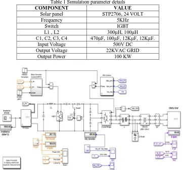
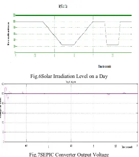
The complete simulation was carried out using the software Sim-Power system tool box of MATLAB. SimPower Systems software and other products of the Physical Modelling product family work together with Simulink software to model electrical, mechanical, and control systems. SimPower Systems extends Simulink with tools for modelling and simulating the generation, transmission, distribution, and utilization of electrical energy. It provide models of a lot of method used in these systems, together with three-phase machines, electric drives, and libraries of application-specific models such as wind-power generation. The single switch high gain dc/dc converter for alternative energy sources MATLAB/Simulink block diagram shows in fig 5.The renewable solar energy gives some potential energy to SEPIC converter, It has high gain output gives to the three level diode clamped three phase inverter and it connected to gird through synchronizing transformer. The output from the PV Module corresponding to the solar irradiation level depicted above is shown in fig (4). The figure clearly illustrates the dependence of PV performance over the level of irradiation.
Table 1 Simulation parameter details
COMPONENT VALUE
Solar panel STP2706, 24 VOLT
Frequency 5KHz
Switch IGBT
L1 , L2 300µH, 100µH
C1, C2, C3, C4 470µF, 100µF, 12KµF, 12KµF.
Input Voltage 500V DC
Output Voltage 22KVAC GRID
Output Power 100 KW
Fig. 5.MATLAB/SIMULINK diagram of grid tie-up inverter using single switch SEPIC converter.
V.OUTPUT RESULTS AND DISCUSSION
Fig.6Solar Irradiation Level on a Day
Fig.7SEPIC Converter Output Voltage
The power injected into the grid by the proposed configuration corresponding to the change in the level of irradiation as what specified earlier is shown in fig. (9).
Fig.9 Grid Power Injections and Inverter Output Power.
Fig.9 shows the dynamic response of the proposed control with the PV system under different levels of the irradiation. During different operating conditions, the dc bus voltage at the input of the grid interfacing inverter is maintained at constant level as can be seen from the fig. (7), which is the output of the SEPIC converter, hence keeping a good functionality of the proposed system configuration thereby to facilitate the active power flow.
VI.CONCLUSION
Solar irradiance to electrical energy using cascaded approach SEPIC with three wire inverter adopting a nonlinear control technique was able to compensate the unbalanced load, the harmonic currents and the reactive power are achieved as well. A modification to the generating reference currents for the nonlinear control using a positive progression rather than a passive filter that has many drawbacks in terms of dynamics and robustness. Also, it is proposes, a sliding mode type of control for a SEPIC converter in order to improve the efficiency and performance of the maximum power tracking. Today, high step up converters play an important role in the engineering. Applications such as Uninterrupted Power Supplies (UPS), electric traction, fuel cell systems and photovoltaic systems rely on such converters.
REFERENCES
[1] Salas, E. Olıas, A. Barrado, A. La´zaro “Review of the maximum power point tracking algorithms for stand-alone photovoltaic systems”, Solar Energy Materials & Solar Cells vol. 90, pp. 1555–1578, 2006.
[2] Sachin Jain and Vivek Agarwal, “A Single-Stage Grid Connected Inverter Topology for Solar PV Systems With Maximum Power Point Tracking”, IEEE Transactions on Power Electronics, vol. 22, no. 5,2007.
[3] D. P. Hohm and M. E. Ropp, “Comparative Study of Maximum Power Point Tracking Algorithms”, Prog. Photovolt: Res. Appl.;11:47–62, 2003
[4] Eftichios Koutroulis, Kostas Kalaitzakis and Nicholas C. Voulgaris, “Development of a Microcontroller-Based Photovoltaic Maximum Power Point Tracking Control System”, IEEE Transactions on Power Electronics, vol. 16, no. 1,2001.
[5] Thomas Bennett, Ali Zilouchian, Roger Messenger, “Photovoltaic model and converter topology considerations for MPPT purposes” Solar Energy, vol. 86, pp. 2029–2040,2012.
[6] Azadeh Safari and Saad Mekhilef, “ Simulation and Hardware Implementation of Incremental Conductance MPPT With Direct Control Method Using Cuk Converter”, IEEE Transactions on industrial electronics, vol. 58, no. 4,2011.
[7] Trishan Esram and Patrick L. Chapman, “Comparison of Photovoltaic Array Maximum Power Point Tracking Techniques”, IEEE Transactions on Energy Conversion, vol. 22, no. 2,2007.
[8] Nicola Femia, Giovanni Petrone, Giovanni Spagnuolo and Massimo Vitelli, “Optimization of Perturb and Observe Maximum Power Point Tracking Method”, IEEE Transactions on Power Electronics, vol. 20, no. 4,2005,
[9] Vladimir V. R. Scarpa, Simone Buso and Giorgio Spiazzi, “Low-Complexity MPPT Technique Exploiting the PV Module MPP Locus Characterization”, IEEE Transactions on Industrial Electronics, vol. 56, no. 5,2009.
[10] Gao, Xianwen, Li, Shaowu, Gong, Rongfen, “Maximum power point tracking control strategies with variable weather parameters for photovoltaic generation systems”, Sol. Energy, 357–367, 1993.
[11] Emilio Mamarelis, Giovanni Petrone, and Giovanni Spagnuolo, “Design of a Sliding-Mode-Controlled SEPIC for PV MPPT Applications” IEEE Transactions on Industrial Electronics, Vol. 61, No. 7, pp. 3387-3398,2014.
[12] Ebrahim Babaei, , and Esmaeel Seyed Mahmoodieh, “Calculation of Output Voltage Ripple and Design Considerations of SEPIC Converter” IEEE Transactions on Industrial Electronics, Vol. 61, No. 3, pp. 1213-1222,2014.
BIOGRAPHY
Samydurai. Twas born in India, in1981. He received the B.E degree in electrical engineering from Government College of Engineering, Salem, Tamilnadu in 2013 and currently doing M.E (Power Electronics and Drives) at K.S.Rangasamy College of Technology, Tiruchengode, Tamilnadu.