CNC Controller System Optimization Using
Software Serial Data Encapsulation
Rohan Kelkar 1
U.G. Student, School of Electrical Engineering, VIT University, Vellore, Tamil Nadu, India1
ABSTRACT: Hardware and software optimization play a key role in order to make the functioning of an embedded system efficient and robust. For obtaining the best possible execution time, the software must be optimized for the hardware used. In this paper, a unique optimization technique is put forth for a CNC controller system due to which execution speed is observed to increase by 34%. The main idea of this technique is to reduce the processing area of the microprocessor or DSP chip by executing certain portions of the code, written specifically for the microprocessor, using a dedicated external software and sending the output results to the microprocessor via a serial interface. The microprocessor then fetches these output parameters generated by the software and uses it further for generating the necessary control signals to drive the motors.
KEYWORDS:Software optimization, efficient, CNC controller, execution speed, reduce processing area.
I. MATERIALS AND METHODS
For the purpose of this research the following technical equipment was used: 1. 3-Axis CNC engraving machine.
2. CimcoEdit software. 3. Type3 software.
4. CNC controller with a DSP microprocessor by Texas Instruments - TMS320LS2407. 5. Serial data cables - RS232C.
6. Newly written special purpose software - Timba 1.0 7. Stepper Motor Drives.
A 3-Axis CNC engraving machine was electronically wired with the above mentioned CNC controller using the stepper motor drives. The motor drives receive control signals from the CNC controller which in turn drive the motors which helps the cutter of the CNC machine to move in the desired direction. Type3 software was used to create design samples which were used for testing purposes. CimcoEdit was used to serially transfer data from the computer to the CNC controller via the serial interface using RS232C connector cable.
II. INTRODUCTION
code depends on the clock speed of the microprocessor but when the processing area of the controller is reduced, the output is obtained relatively quickly. Usually, when the NC file is received by the controller via the serial interface, it runs a decryption algorithm due to which it understands the file and later follows a set of different procedures due to which the necessary control signals for the motors are generated. But the proposed special purpose software (Timba 1.0) decrypts the file externally and sends only the necessary data in a hidden format due to which a large amount of processing is avoided by the controller which in turn allows it to generate the output in a relatively short amount of time.
III.CAD-CAM
1. CAD - Computer Aided Design
A computer aided design software or a CAD software is primarily used to do two dimensional or three dimensional modelling. It provides various modelling features and tools which can be used to design various items be it 2D or 3D. It finds application in broad range of industries such as jewellery, architecture, mechanical engineering industries, tile designers etc. CAD softwares have essentially replaced the traditional hand designing methodologies followed during the early nineties with a computer based approach. It thus provides a faster way of designing, modifying or editing a 2D or a 3D design. It has greatly increased the efficiency and the productivity of a designer as it provides a full proof solution of bringing our imaginative designs into the real world. One famous example is AutoCAD which is used widely by architects or technicians in mechanical based industries to generate drawings based on their individual interests and purposes[3].
The CAD software used for our research was 'Type3'. This software provided a solid base to generate various 2D and 3D designs for testing purposes in this experiment. Creating designs using this software is extremely easy as the front end is designed in such a way that it provides ultimate ease of use[4].
2. CAM - Computer Aided Machining/Manufacturing
A CAM software finds application in the manufacturing of machine tools in the form of milling, engraving, cutting, routing etc[5]. A CNC machine can be controlled using a CAM software as this software provides the necessary controls required to communicate with a CNC machine via a computer. It also provides a utility which facilitates the conversion of a design file created by a CAD software, into an NC (Numerical Control) file which can be electronically deciphered or understood by the CNC controller of the machine. The software also provides a serial communication facility using which the NC file can be transferred to the CNC machine with the help of a serial interface. Generally, the computer is connected to the machine using a RS232C cable connector setup which provides the necessary speed for serial communication between the CAM software and the controller.
The CAM software used for our research was CimcoEdit[6]. It provides a simple but sophisticated way of transferring the NC file to the controller. It also provides options such as editing the feed rate, plunge rate, baud rate etc. In this experiment the time required for cutting a certain sample using CimcoEdit was compared with the time required for cutting the same sample using the special purpose software (Timba 1.0) written for the purpose of this research.
IV. CNCCONTROLLER
The controller used for this experiment was a logic board developed using the DSP microprocessor by Texas Instruments - TMS320LS2407. It is a 16 bit fixed point DSP with flash[7]. In today's times almost all controllers follow the Bresenham's algorithm in order to generate control signals to move in a straight line. Even for drawing circles, a different form of the same algorithm is followed. Therefore, the controller we used carried out two major processing parts due to which it resulted in introducing a small delay before it actually drove the motors connected.
1. Extraction and Decryption
This is the first step followed by the CNC controller in which it fetches the data from the serial port and enters the decryption algorithm method. Firstly, it builds the serial connection with the CAM software and assigns the baud rate for the communication to begin. Handshaking is ensured only when the baud rate of the receiver (CNC controller) and that of the transmitter (CAM software) is same[8]. Next, data is received in a stream. After receiving every coordinate, the controller stops and decrypts the data in order to understand which coordinate it has actually received. Therefore after receiving every coordinate in an encrypted format, the controller introduces a delay in the entire process. Let us call this delay as D1. The decryption method is also a long and a complicated algorithm which involves multiple function calls and thus introduces a delay in the system purely because of its length. Let us call this delay as D2. Although D1 and D2 are respectively very small, extraction and decryption takes place a number of times due to which the collective delay introduced in the system is of some concerning value. The number of extraction and decryption cycles will always be equal to the number of coordinates sent.
2. Bresenham's algorithm and Vector3D
The Bresenham's line generator algorithm is a very famous algorithm used in CNC controllers to generate the necessary control signals in order to move the spindle/cutter setup from the first point to the second point[9]. This algorithm also finds application in graphic softwares which help us generate lines on the computer screen. Dedicated chip sets or co-processors are also manufactured which follow this algorithm and generate lines for graphics applications. The CNC machine used in this experiment had stepper motors installed and therefore needed step and direction only in order for it to move. This machine was a 3-axis CNC machine and therefore a separate stepper motor was installed for every axis namely X,Y and Z. Bresenham's algorithm firstly calculates the direction and distance between the current coordinate and the destination coordinate. It does so for the coordinates of the X-axis, Y-axis and the Z-axis respectively. After calculating the direction and distance to be travelled for every motor, it assigns number of steps and direction to control variables which correspond to each axis. Thus, say Sx and Dx are control variables for step and direction respectively for the X-axis. Likewise, Sy,Dy,Sz and Dz are also assigned respective values based on the coordinates received. Next, all six control variables are passed into a function called Vector3D.
Vector3D is responsible for generating pulses using which the motors are moved. After the Bresenham's algorithm is executed, Vector3D receives the values of the control variables and runs a routine which carries out pulse width modulation (PWM) for generating pulses for driving the motors[10]. It also takes into consideration the direction control variables and therefore the motors are always driven in the desired direction. A separate routine is also made to run in parallel which times which motor should be driven at what point in time due to which the system makes sure that the X,Y and Z axis motors always move in harmony resulting in a smooth line generation while travelling from the current coordinate to the destination coordinate.
The sheer length and complexity of the Bresenham's algorithm introduces a delay D3 in the entire system.
V. SPECIAL PURPOSE SOFTWARE - TIMBA 1.0
with options such as selecting the COM port and setting the baud rate value. Using this information it confirms handshaking between the software and the CNC controller.
The software fulfils the main idea of reducing the processing area of the DSP chipset by running the decryption algorithm and the Bresenham's algorithm by itself before transferring any data to the CNC controller. This results in it directly generating the control variables required for Vector3D function to drive the motors. Carrying out the decryption and the Bresenham's algorithm externally in this special purpose software eliminates the introduction of delays D2 and D3 as discussed earlier. After running the decryption and Bresenham's algorithm, the software now serially sends the values of the six control variables over to the CNC controller. The controller too is programmed to fetch these values and directly call the Vector3D function which further drives the motors according to the data received. The DSP chip used in the controller does not need to process large lengths of code due to this setup and thus a very small delay is introduced in the system compared to the previous setup wherein the DSP chipset had to run large codes written for decryption and Bresenham's algorithm. Thus, this is how the processing area for the DSP chipset was reduced which resulted in drastic increase of the processing speed of the controller.
VI. RESULTS
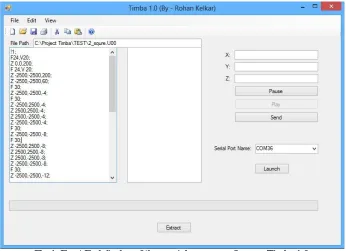
The following figure (Fig.1) shows the front end interface of the special purpose software written for the purpose of this research experiment. It is a simple but intuitive graphical user interface which allows the user to open and send NC files to the CNC controller. It also provides the user with the option of selecting the COM ports from a list of existing available COM ports.
Fig 1. Front End display of the special purpose software - Timba 1.0
Sr. No. Feed Rate Execution time using CimcoEdit (in seconds)
Execution time using Timba 1.0 (in seconds)
Percentage increase in cutting speed
1 20% 450 297 34%
2 30% 300 201 33%
3 40% 225 148.95 33.8%
4 50% 180 118.8 34%
5 60% 150 102 32%
6 70% 128.5 84.55 34.2%
7 80% 112.5 72 36%
8 90% 100 66.5 33.5%
9 100% 90 58.95 34.5%
Table 1. Showing percentage increase in cutting speed after using the special purpose software Timba 1.0
VII. CONCLUSION
Optimization of the software and hardware is a must while designing embedded systems. This ensures maximum efficiency and speed of execution due to low delay generation. In this research experiment, the processing area of the DSP chipset of the CNC controller was drastically reduced which resulted in an overall increase in the cutting speed of the machine to about 34%. In order for the special purpose software to work this way, the code run by the DSP chip was also changed a bit to receive the control variables directly over the serial interface and then call the Vector3D function to run the motors. While carrying out engraving jobs requiring a high time of cutting, the overall time saved due to this set up is immense. In industries where such cutting jobs are done on a large scale, a lot of time will be saved per sample which may result in a considerable amount of profit generation for the company.
REFERENCES
1. https://en.wikipedia.org/wiki/Numerical_control 2. www.autodesk.com/solutions/cad-cam
3. https://en.wikipedia.org/wiki/Computer-aided_design 4. www.type3.com/
5. https://en.wikipedia.org/wiki/Computer-aided_manufacturin 6. www.cimco.com/product_edit_description.php3
7. http://www.ti.com/product/tms320lf2407
8. http://tanmayonrun.blogspot.in/2011/06/what-is-handshaking-write-suitable.html 9. https://en.wikipedia.org/wiki/Bresenham%27s_line_algorithm