Design an Area and Delay Optimized VLSI Architecture
for DWT Using Lifting Scheme
Sravani Mandyam 1, B. Lokeshwar reddy (Assistant professor) 2
BES group of institutions. Golden Valley integrated campus, Angallu, Andhra Pradesh
ABSTRACT:
The fundamental idea behind wavelets is to analyze according to scale. Indeed, some researchers in the wavelet field feel that, by using wavelets, one is adopting a perspective in processing data. Wavelets are functions that satisfy certain
mathematical requirements and are used in representing data or other functions. In
this paper, separable pipeline architecture for fast computation of the 2D DWT with a less area and low latency is proposed by using carry select adder. The low latency and less area is achieved by proper designing of 2-D DWT filtering processes and also efficiently transferring the data between the 2-D DWT filters.
Keywords: DWT, Seperable, Xilinx ISE , Verilog
I. INTRODUCTION
The 2-D discrete wavelet transforms (DWT) have been widely used in many applications like image compression, signal processing, speech compression because of their multi-resolution of signals with localization both in time and frequency. In the past, much
architecture has been proposed aimed at providing high – speed 2-D DWT computation with the requirement of utilizing a reasonable amount of hard ware resources. These architectures can be broadly classified into separable [1]-[5] and non-separable architectures [2]-[6]. The separable method is the most straight forward implementation method. In separable method, a 2-D filtering operations, one for processing the data row-wise and the other column-wise. In this method the intermediate coefficients
stores in a frame memory first. Then it performs 1-D DWT in other direction with
these intermediate coefficients to complete one-level 2-D DWT .Because the size of this frame memory is usually assumed to off chip.
separable method does not require a frame memory to store the intermediate data. Instead, some internal line buffers are used to store the intermediate data, and the required size is proportional to the image width. Vishwanath et al. [1] have proposed a low-storage short-latency separable
architecture in which the row wise operations are performed by systolic filters and the column operations by parallel filters. In non separable architectures the 2-D transforms are computed directly by using 2-D filters. chakrabarti et al. [2] have proposed two non separable architectures, one using parallel 2-D filters and the other an SIMD 2-D array ,both based on a modified RPA.
In non separable method internal line buffers are use to store the boundary data among neighbor blocks such as to keep the required external frame memory bandwidth as low as the separable method. However, the external memory access would consume the most power [10] and become very sensitive in the case of system on chip. In addition, the required external memory bandwidth of the non-separable is more than the double of the
separable method. The most existing separable architectures aim at providing fast computation of the DWT by using pipeline and a large number of parallel
filters and systolic filters. However these existing architectures have large latency and memory size increases because of by providing additional requirement of transposing the intermediate data between the two 1-D filtering processes.
II. PIPELINE FOR THE 2-D DWT
COMPUTATION
In a pipeline structure for the DWT computation, multiple stages are used to carry out the computations of the various decomposition levels of the transform [4]. The computation corresponding to each decomposition level needs to be mapped to a stage or stages of the pipeline. In order to design a pipeline structure capable of performing a fast computation of the DWT with low expense on hardware resources and low design complexity, an optimal mapping of the overall task of the DWT computation to the various stages of the pipeline needs to be determined. Any distribution of the overall task of the DWT computation to stages must consider the inherent nature of the sequential computations of the decomposition levels that limit the computational parallelism of the pipeline stages, and consequently the
minimum and proportional to the amount
of the task assigned to the stage.
Fig 1 Pipeline structure with N stages
A straightforward of mapping of the overall task of the DWT computation to a pipeline is one-level to one-stage mapping, in which the tasks of J decomposition levels are distributed to J stages of the pipeline. However, dividing a stage of the
one-level to one stage pipeline into multiple stages would require a division of the task associated with the corresponding decomposition level into sub-tasks, which in turn, would call for a solution of even a more complex problem of synchronization of the sub-tasks associated with divided stages. On the other hand, merging multiple small-size stages of the pipeline into one stage would not create any additional synchronization problem. As a matter of fact, such a merger could be used to reduce the overall number of filter units of the pipeline.
III. Synchronization of stages
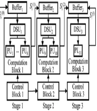
The distribution of the computational load among the three stages, and the hardware resources made available to them are in the ratio 8:2:1. The stages of pipeline need to be synchronized in such a way that each stage starts the operation at an earliest possible time when the required data
become available for its operation. Once the operation of a stage is started, it must continue until the task assigned to it is fully completed.
Consider the timing diagram given in Fig. 2 for the operation of the three stages, where t1,t2 and t3 are the times taken individually by stages 1,2 and 3, respectively, to complete their assigned tasks, and ta and tb are the times elapsed between the starting points of the tasks, by stages 1 and 2, and that stages 2 and 3 respectively.
Fig2.Timing diagram for the operation
of three stages
individual stages are approximately the same, since the ratios of the tasks assigned and the resources made available to the three stages are the same. The average times to compute one output sample by stages 1, 2 and 3 are in the ratio 1:4:8. In Fig. 2 the relative widths of the slots in the
three stages are shown to reflect this ratio. Our objective is to minimize the total computation time ta+tb+t3 by minimizing t,t and t individually.
Design of stages In the proposed three-stage architecture, three-stages 1 and 2 perform the computations of levels 1 and 2 respectively, and stage 3 that of all the remaining levels. Fig. 3 shows the block diagram of the three-stage architecture.
Fig. 3. Block diagram of three stages architecture
IV. Different types of transforms
1. DCT (Discrete Cosine Transform).
2. DWT (Discrete Wavelet Transform). .
4.1 The Discrete Cosine Transform
(DCT)
The discrete cosine transform
(DCT) helps separate the image into parts
(or spectral sub-bands) of differing
importance (with respect to the image's
visual quality). The DCT is similar to the
discrete Fourier transform: it transforms a
signal or image from the spatial domain to
the frequency domain.
4.2 Discrete Wavelet Transform (DWT)
The discrete wavelet transform
(DWT) refers to wavelet transforms for
which the wavelets are discretely sampled.
A transform which localizes a function
both in space and scaling and has some
desirable properties compared to the
Fourier transform. The transform is based
on a wavelet matrix, which can be
computed more quickly than the analogous
Fourier matrix. Most notably, the discrete
wavelet transform is used for signal
coding, where the properties of the
transform are exploited to represent a
discrete signal in a more redundant form,
often as a preconditioning for data
compression. The discrete wavelet
transform has a huge number of
applications in Science, Engineering,
Wavelet compression is a form of
data compression well suited for image
compression (sometimes also video
compression and audio compression). The
goal is to store image data in as little space
as possible in a file. A certain loss of
quality is accepted (Lossy Compression).
Fig4: Proposed Architecture
Using a wavelet transform, the
wavelet compression methods are better at
representing transients, such as percussion
sounds in audio, or high-frequency
components in two-dimensional images,
for example an image of stars on a night
sky. This means that the transient elements
of a data.
Signal can be represented by a
smaller amount of information than would
be the case if some other transform, such
as the more widespread discrete cosine
transform, had been used.
First a wavelet transform is
applied. This produces as many
coefficients as there are pixels in the image
(i.e.: there is no compression yet since it is
only a transform). These coefficients can
then be compressed more easily because
the information is statistically concentrated
in just a few coefficients.
4.3 Ripple Carry Adder:
The ripple carry adder is constructed by cascading full adders (FA)
blocks in series. One full adder is responsible for the addition of two binary digits at any stage of the ripple carry. The carryout of one stage is fed directly to the carry-in of the next stage. Even though this
is a simple adder and can be used to add unrestricted bit length numbers, it is however not very efficient when large bit
numbers are used. One of the most serious drawbacks of this adder is that the delay
increases linearly with the bit length. The worst-case delay of the RCA is when a carry signal transition ripples through all
Fig.5 Ripple carry adder
4.4 Carry Select adder:
The CSLA is simple but rather fast, having a gate level depth. Adding two n-bit numbers with a CLSA is done with two RCA adders in order to perform the calculation twice, one time with the assumption of the carry being zero and the other assuming one. After the two results is calculated, the correct sum, as well as the correct carry, is then selected with the multiplexer once the correct carry is known. The RCA is constructed by cascading FA blocks in series
Fig.6 Carry Select Adder
One FA is responsible for the addition of two binary digits at any stage of the ripple carry. The carryout of one stage is fed directly to the carry-in of the next stage 4-Bit RCA. A serious drawback of this adder is that the delay increases linearly with the bit length. CSLA is to implement large bit-width adders with less delay. In CSLA, increasing size are connected in a cascading structure. The objective of CSLA design is to provide a parallel path for carry propagation that helps to reduce the overall adder delay.
V. Similarities between Fourier
and Wavelet Transform
are both linear operations that generate a data structure that contains segments of various lengths, usually filling and transforming it into a different data vector of length .
The mathematical properties of the matrices involved in the transforms are similar as well. The inverse transform matrix for both the FFT and the DWT is the transpose of the original. As a result, both transforms can be viewed as a rotation in function space to a different domain. For the FFT, this new domain contains basis functions that are sines and cosines. For the wavelet transform, this new domain contains more complicated basis functions called wavelets, mother wavelets, or analyzing wavelets.
Both transforms have another similarity. The basis functions are localized in frequency, making mathematical tools such as power spectra (how much power is contained in a frequency interval) and scale grams (to be defined later) useful at picking out frequencies and calculating power distributions.
5.1 Dissimilarities between
Fourier and Wavelet Transform
The most interesting dissimilarity between these two kinds of transforms is that individual wavelet functions are
localized in space. Fourier sine and cosine functions are not. This localization feature, along with wavelets' localization of frequency, makes many functions and operators using wavelets "sparse" when transformed into the wavelet domain. This sparseness, in turn, results in a number of
useful applications such as data compression, detecting features in images, and removing noise from time series.
5.2 Wavelets for image
compression:
Wavelet transform exploits both the spatial and frequency correlation of data by dilations (or contractions) and translations of mother wavelet on the input data. It supports the multi-resolution analysis of data i.e. it can be applied to
different scales according to the details required, which allows progressive
transmission and zooming of the image without the need of extra storage. Another encouraging feature of wavelet transform is its symmetric nature that is both the forward and the inverse transform has the same complexity, building fast compression and decompression routines. Its characteristics well suited for image compression include the ability to take into account of Human Visual System’s (HVS)
compaction capabilities, robustness under transmission, high compression ratio etc.
Wavelet transform divides the information of an image into approximation and detail sub-signals. The approximation sub-signal shows the general trend of pixel values and other
three detail sub-signals show the vertical, horizontal and diagonal details or changes in the images. If these details are very small (threshold) then they can be set to zero without significantly changing the image. The greater the number of zeros the greater the compression ratio. If the energy retained (amount of information retained by an image after compression and decompression) is 100% then the compression is lossless as the image can be reconstructed exactly. This occurs when the threshold value is set to zero, meaning that the details have not been changed.
Wavelet has many uses in image processing such as image compression, image enhancement, image restoration,etc.
VI. Synthesis Results:
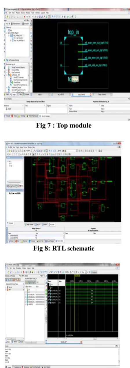
Fig 7 : Top module
Fig 8: RTL schematic
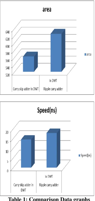
Table 1: Comparison Data graphs
Parameter Carry select adder in
DWT
Ripple carry adder
In DWT Speed 14.448ns 17.829ns
Area 562 625
Table 2: Comparison table
VII. Conclusion
In this paper, separable pipeline architecture for fast computation of the 2-D 2-DWT with a less area and low latency is proposed by using carry skip adder.
Comparing with ripple carry adder, carry select adder is very high speed. The low latency and less area is achieved by proper designing of 2-D DWT filtering processes and also efficiently transferring the data between the 2-D DWT architectures. This architecture is simulated, synthesized and
implemented by VERILOG language using XILINX ISE Tool.
References:
[1]. M. Vishwanath, R. Owens, and M. J. Irwin, “VLSI architectures for the discrete wavelet transform,” IEEE Trans. Circuits
Syst. II, Analog. Digit. Signal Process. vol. 42, no. 5, pp. 305–316, May 1995
[2] C. Chakrabarti and M. Vishwanath, “Efficient realizations of the discrete and
continuous wavelet transforms: From single chip implementations mapping on SIMD array computers,” IEEE Trans. Signal Process., vol. 43, no. 3, pp. 759– 771, Mar. 1995.
[3] H. Y. Liao, M. K. Mandal, and B. F. Cockburn, “Efficient architectures for 1-D
and 2-D lifting-based wavelet transforms,” IEEE Trans. Signal Process., vol. 52, no. 5, pp. 1315–1326, May 2004.
[5] M. Alam, W. Badawy, V. Dimitrov, and G. Jullien, “An efficient architecture for a
lifted 2-D biorthogonal DWT,” J. VLSI Signal Process., vol. 40, pp. 333–342, 2005.
[6] C. Yu and S.-J. Chen, “VLSI implementation of 2-D discrete wavelet
transform for real-time video signal processing,” IEEE Trans. Consum.
Electron. vol. 43, no. 4, pp. 1270–79, Nov. 1997.
[7] P.-C. Wu and L.-G. Chen, “An efficient architecture for two-dimensional discrete wavelet transform,” IEEE Trans. Circuits
Syst. Video Technol. vol. 11, pp. 536–545, Apr. 2001.
[8]. C.-T. Huang, P.-C. Tseng and L.-G. Chen, “Memory Analysis and Architecture
for Two-Dimensional Discrete Wavelet Transform,” in Proceedings of the IEEE
Int. Conf. on
Acoustics, Speech and Signal Processing, 2004, pp. V13– V16.
[9]. P.-C. Tseng, C.-T. Huang and L.-G. Chen, “Generic RAM Based Architecture
for Two-Dimensional Discrete Wavelet Transform with Line-Based Method,” in Proceedings of the
Asia-Pacific Conference on Circuits and Systems, 2002, pp. 363– 366.
[10] M. Vishwanath, R. Owens, and M. J. Irwin, “VLSI architectures for the discrete
wavelet transform,” IEEE Trans. Circuits