Improve the Performance of OFDM Based Wave by Applying A Series of
Sequential Levels of Encryption / Decryption
1BHUTHARAJU MAHESH,2B.BHARATHI,3NAGA VIJAY KUMAR REDDY.T
1
PG Scholar, Department of ECE, SREE DATTHA GROUP OF INSTITUTIONS, Hyderabad.
2
ASSISTANT PROFESSOR, Department of ECE, SREE DATTHA GROUP OF INSTITUTIONS,
Hyderabad.
3 ASSISTANT PROFESSOR, Department of ECE, SREE DATTHA GROUP OF INSTITUTIONS,
Hyderabad
ABSTRACT
The orthogonal frequency division
multiplexing (OFDM) has been adopted as the downlink transmission scheme for the Long-Term Evolution (LTE) and is also used for several other radio technologies, e.g. WiMAX and the DVB broadcast technologies. The conventional OFDM depends on Fourier transform is called FFT based OFDM. The FFT based OFDM have a drawbacks of high PAPR and consuming bandwidth by inserting cyclic prefix. This paper uses a wavelet based OFDM instead of FFT based OFDM to solve its problem. This paper uses series concatenated encoder/decoder levels of hamming and convolutional encoder as a channel codding technique to improve the system performance.
1. Introduction
The mobile communication systems such LTE have a high data rates in upload and download which provide the customers with new services. OFDM uses the orthogonal subcarriers to consume the bandwidth with minimized interference. The wavelet based OFDM enhancement the system performance by reducing the bit error rate (BER). This paper apply a new channel encoder technique depends on using more than one encoder type to add
the advantages of each one in the same
systemwhich is called the series
concatenated encoder/decoder levels. The conventional FFT based OFDM uses one stage of the convolutional encoder to reduce BER [1]. This paper used a wavelet
based OFDM with hamming and
convolutional encoder in a series
concatenated encoder/decoder levels.
2. Wavelet based OFDM system
OFDM is the most effective type of the multicarrier modulations which divide the whole spectrum into equally spaced frequencies orthogonally on each other to avoid the interference. The FFT based OFDM uses a cyclic prefix which consumes 25% from the bandwidth. The wavelet based OFDM don’t use the cyclic prefix insertion and solve this problem to save the wasted bandwidth. The wavelet based OFDM systems employ Low Pass Filter (LPF) and High Pass Filter (HPF) operating as Quadrature Mirror Filters (QMF) satisfying perfect reconstruction and orthonormal bases properties. The transforms use filter coefficients as approximate and detail in LPF and HPF
respectively. The approximated
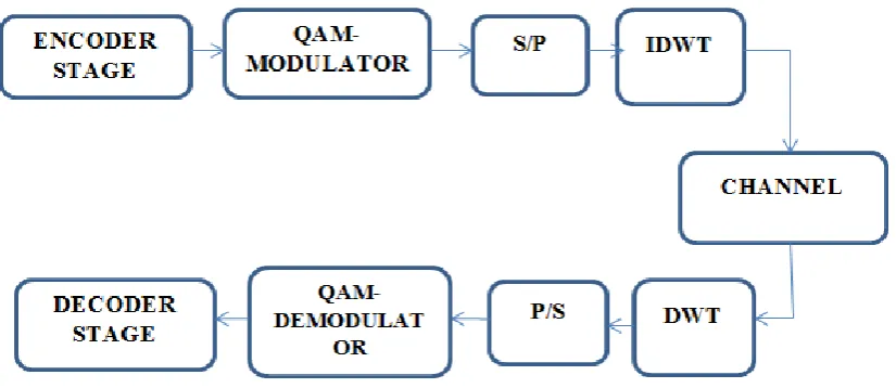
sub-band coding since the signals are divided into sub-signals of low and high frequencies respectively.The general block diagram of wavelet based OFDM is shown in Fig. 1.The binary data is the encoder’s
input which modulated by M-QAM modulator and then translated from serial to parallel to enter the IDWT block before the channel. The receiver makes the reverse process [3].
Fig. 1 the wavelet based OFDM block diagram
3. Channel codding
The channel codding is a class of signal transformation which designed to improve the communication performance of the transmitted signal against the channel impairments such as noise, interference and fading. The channel codding classified into the waveform codding and the structure codding. The waveform codding transformed the waveform into better waveform to minimize the errors such as
the M-ary signaling, Antipodal,
Orthogonal and the trellis codding
modulation (TCM) [4]. The structure sequence channel codding transforming the data sequences into better sequence with the redundancy bits. The redundant bits used for the error detections and correction such as the block codding, Convolutional codding and turbo codding. This paper discuss the bit error rate (BER)
versus the signal to noise ratio (SNR) for the main block codding types and the convolutional codding to be compared with the multi levels of combination codes.
3.1The Block codes
The source data of length m bits is segmented into a blocks of data of length k bits of message bits. The encoder transfers the message bits into coded bits of length n. the redundant is the n-k bits which carry no new information. The code formula is (n,k) for a code rate of k/n. for any block code (n, k) for small values of n,k there is
a simple look-up table of length 2k which
codes are the hamming codes, Extended Golay Codes and BCH codes [5] [6] [7].
3.2 The Hamming codes
The hamming codes are a simple class of the block codes which can be detect and correct single bit errorin a block of data and take the form [8] [9]:
(n,k) = (2m -1, 2m-1- m) where m>1 and dmin =3 (1)
3.2.1 The hamming codes advantages
a. Correcting all single error so have good performance
b. Detecting all the combination of two or more errors within the block
c. Suited for random bit errors for the transmitted signal
d. Not suited for the channel of burst errors
e. Easy to implement
f. Low cost and low power applications
g. Low simulation time as studied in this paper
3.2.2 The BER for hamming encoder
The bit error probability represented as [4]:
PB = (2)
Where, P is the channel symbol error. The above equation takesa simplified form as shown [4]:
PB= p – p (1-p) n-1 (3)
The modulation used in this paper is the M-QAM modulator, the channel symbol error (p) in M-QAM modulation is [11]:
Pm-qam = 4 – 4
(4)
Substitute in Eq. (3) to obtain the bit error rate probability for hamming encoder at M-QAM:
Pbhamming_mqam = {[4 –
4 ]– [4
–
4 )][(1-[(4
–4
]n-1}
(5)
The bit error rate for M-QAM modulation at hamming encoder depends on the M
levels of the input symbols which equal 2k
for k binary bits selected for the system and the signal bit power to noise power.
The theoretical results for 16-qam
modulation at hamming encoder the BER gives a value of 4.6 * 10^-3 at 10dB SNR ratio. The simulation time is 2.4 sec. The hamming encoder circuit consists of six XOR, one multiplexer . The hamming decoder circuit consists of nine XOR gates and seven OR gates and multiplexer and one 3 x 8 decoder.
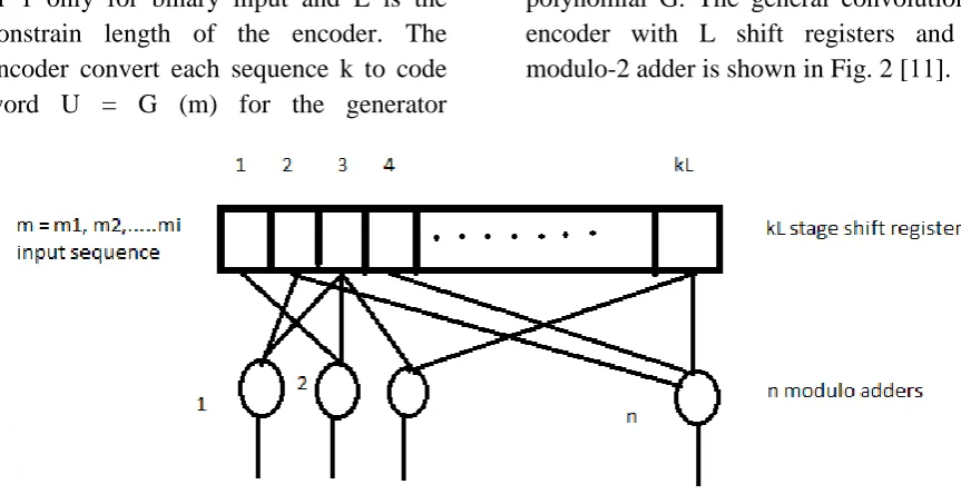
3.3The convolutional encoder
The convolutional encoder take the form of (n,k,L) where n is the code word, k is
the input sequence and equal
or 1 only for binary input and L is the constrain length of the encoder. The encoder convert each sequence k to code word U = G (m) for the generator
polynomial G. The general convolutional encoder with L shift registers and n modulo-2 adder is shown in Fig. 2 [11].
Fig. 2 The convolutional encoder
The encoder rate is k/n and the constrain length K represent the number of k bit shifts which the information sequence influence the encoder output. The shift register consists of number of k flip flops [8] [12].
3.3.1 The maximum likelihood detection
The decoder that achieve minimum error probability called the likelihood function p(Z|U) where Z is the received sequence at
a transmitted bits U. the decoder choose the maximum U’ if:
P(Z|U) = max (p(Z|U’)) for all U (6)
The detector using for the convolutional encoder is the Viterbi decoder. The block diagram of the Viterbi decoder is shown in Fig. 3 [13][14]
Fig.3 Viterbi encoder block diagram
The decoder is composed of an array of logical blocks which compute the branch metric from BMU (branch metric unit),
distance between the received code word and two possible transition values and the
block diagram of BMUis shown in Fig. 4.
Fig.4 BMU block diagram
The path metric unit computes the most likely input path to obtain the information
with minimum errors and the block diagram of PMU is shown in the Fig. 5.
Adding the branch metric and path metric together for each of the two inputs produces two numbers which indicate how much error (or "noise" as it's often called) previous nodes have accumulated. We select the path with the lowest error value and pass it on to the next stage.The convolutional encoder consists of n modulo-2 adder and k stage shift register. Viterbi decoder consists of two adders, one multiplexer, one comparator, two sums and two XOR gates.
3.3.2 The bit error probability of a convolutional encoder for M-QAM
The bit error rate probability for a convolutional encoder at hard decision is represented as [4]:
PB ≤ at N=1 and D=2
(7)
Where, p is the probability of channel symbol error, D is the hamming distance from the branch word of that branch to all zero branch and T (D, N) is the transfer function of the system which can be represented as [15]:
T (D,N) =
(8)
Differentiate and substitute in Eq. (7) to find the bit error rate probability in terms of the channel symbol error [4]:
PB =
(9)
Substitute in Eq. (4) to find the final form of bit error rate probability in M-QAM modulation:
PB =
(10)
The theoretical results for 16-QAM modulation at convolutional encoder gives a value of BER at 10dB SNR ratio is equal to 0.0377 at a simulation time of 18 sec.
3.4 The series concatenated encoder/decoder levels
Fig. 6 the Block diagram of series concatenated encoder/decoder levels
The convolutional (ni, ki) with code rate of ri=ki/ni, the hamming encoder (no, ko) with a code rate of ro. The series concatenated encoder/decoder levels have a code rate r=ri * ro. the error correcting
probability for hamming encoder t= (dmin
-1)/2 for example if dmin = 3 then th=1, for
convolutional encoder t= (df -1)/2 for df= 5
then tconv=2 . The error correcting
probability for the series concatenated encoder/decoder levels is the summation
of the two codes which gives tseries
concatenated=3. Then, the series concatenated
encoder/decoder levels increase the error correcting probability.
The probability of error in series concatenated encoder/decoder levels
The Bit error rate Probability for the series
concatenated encoder/decoder levels
computed by the following steps [16] [17]:
1- Find the BER for inner code Pinner
from Eq. 10 for example
convolutional encoder gives a BER of 0.0377 at 10dB SNR.
2- Find the probability of symbol
error at the outer encoder Ps outer =
1-(1-Pinner)ki for example the
probability of symbol error rate
channel at hamming encoder
depends on the convolutional encoder equal
3- Find the BER for outer codes
depends on Psinnerfrom Eq.5 for
example the BER at concatenated level is 1.3*10^-3 which is less than the hamming encoder single
stage and the convolutional
encoder single stage.
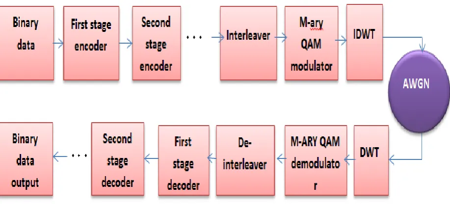
4. Simulation and results
The simulation parameteres specification
modulation 16-QAM
Wavelet function Haar
(n,k) (6,3)
Constrain length [177 133]
Binary data 96k bits
Encoder/decoder Convolutional/Viterbi – hamming
Table 1: The simulation parameters
The simulation of wavelet based OFDM using the multi levels of the encoding studied in different cases for this paper. The results studied for series concatenated encoder/decoder levels at two or more
convolutional or hamming
encoder/decoder and a combination of hamming and convolutional encoder as shown in Fig. 7.
Fig. 7 The block diagram of Wavelet based OFDM transceiver for series concatenated encoder/decoder levels
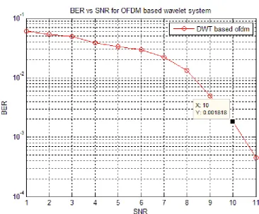
4.1One stage hamming encoder
decoder in wavelet based OFDM
The wavelet based OFDM using one stage hamming encoder / decoder simulated
Fig. 8 BER for one stage of hamming encoder/decoder
The value of BER gives 1.8 * 10-3 at 10dB
SNR at a simulation time of 2.4 sec. This value means that for every transmitted million bits there are 1818 error bits. This result will be compared with the one stage convolutional encoder as in [18]. BER for hamming encoder less than BER for convolutional encoder and low simulation time but the complexity increased. The
series concatenated encoder/decoder
levelscan be studied to obtain less BER, accepted simulation time and allowed complexity.
4.2The series concatenated
encoder/decoder levels
The series concatenated encoder/decoder levels using more than one stage in the encoder and decoder circuit diagram.
4.2.1 Twoseries concatenated levels of convolutional encoder/ Viterbi decoder
The conventional wavelet based OFDM uses a one stage of convolutional encoder and gives a good results compared with FFT based OFDM and no codding system [18]. The two stages convolutional encoder uses series concatenated encoder/decoder levels of convolutional encoder in the transmitter and also series concatenated encoder/decoder levels of Viterbi decoder at the receiver. The relation of BER versus SNR is shown in Fig. 9.
Fig. 9 BER for two stages of convolutional encoder/ Viterbi decoder
required for this system is nearly 23.79 sec. the convolutional encoder is simple but has slightly increased in BER than the hamming encoder and also a high
simulation time. The two stages
convolutional encoder gives good results with respect to the one stage convolutional encoder but the hamming encoder gives better results than one and two stages convolutional encoder.
4.2.2Two series concatenated levels of hamming encoder/decoder
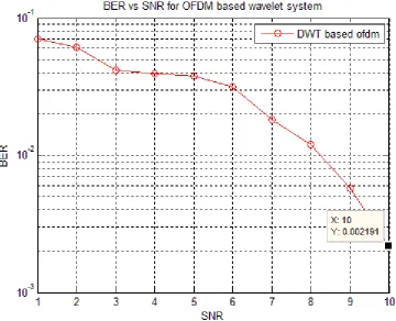
The two stages hamming encoder uses two series concatenated hamming encoders in the transmitter and also two series concatenated hamming decoders at the receiver. BER versus SNR for two stage hamming encoder/decoder is shown in Fig. 10
Fig. 10 BER for two stage hamming encoder/decoder
The value of BER equal 0.002191 at 10dB SNR which means that for every million transmitted bits there are nearly about 2191 bits with errors. The simulation time
required for two stage hamming
encoder/decoder is 3.2 sec only. The BER value for two stages convolutional encoder/Viterbi decoder is less than BER
value for two stages hamming
encoder/decoder at the same SNR by a small amount. Which indicate that the difference in BER value is not high to
choose the best, but the simulation time in two stages hamming encoder/decoder is less than the simulation time of two stages convolutional encoder/Viterbi decoder by more than 6 times, then the two stages hamming is the best to save the time.
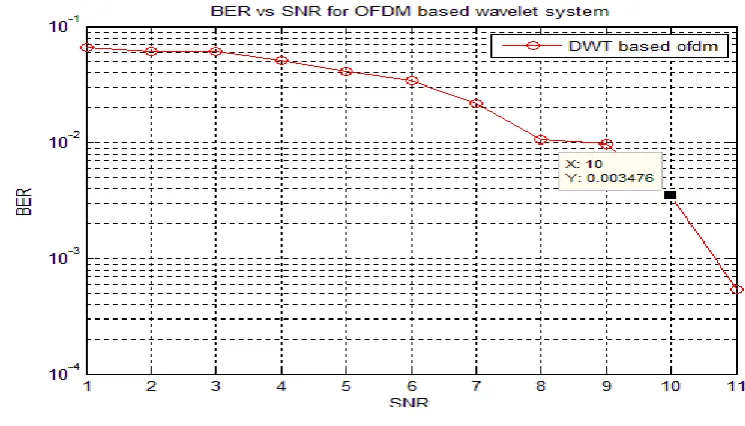
4.2.3 Two series concatenated levels
ofhamming-convolutionalencoder/decoder
as a first stage in the transmitter followed by a convolutional encoder as a second stage. At the receiver the convolutional decoder is the first stage and then the
hamming decoder. BER versus SNR in
two stages hamming/convolutional
encoder/decoder is shown in Fig. 11.
Fig. 11 BER in two stages hamming/convolutional encoder decoder
The value of BER in two stages
hamming/convolutional encoder/decoder
gives 0.0006818 at 10dB SNR which means that for every 10 million transmitted bits there are 6818 error bits only. Cascading a convolutional encoder with hamming gives a decreased BER at the same SNR. The simulation time required is
about 3.48 sec. The two stages
hamming/convolutional encoder gives less BER and less simulation time. Using a series concatenated for hamming and convolutional encoder/decoder gives a BER less than two or three times of the other systems with saving time and complexity.
The three stages convolutional encoder uses three convolutional encoders in the transmitter and three Viterbi decoders at the receiver. BER versus SNR in three stages convolutional encoder is shown in Fig. 12.
Fig. 12 BER in three stages convolutional encoder
The value of BER in three stages convolutional encoder is 0.003281 at 10dB SNR. The simulation time required is 42 sec. When the number of convolutional encoder/Viterbi decoder stages increased the simulation time also increased because of the increasing of complexity and hence the BER value increased.
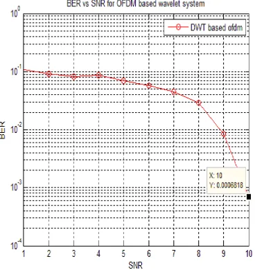
4.2.5 Three series concatenated levels of hamming encoder
The three stages hamming encoder uses three cascaded hamming encoders in the transmitter and three cascaded hamming decoder in the receiver. BER versus SNR for three stages hamming encoder/decoder is shown in Fig. 13.
BER value in three stages hamming encoder/decoder is 0.003476 at 10dB SNR. The simulation time required for three stages hamming encoder/decoder is 21sec. As the number of stages increased
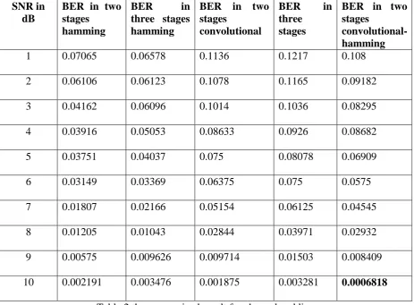
the circuit complexity increased and the simulation time also increased without any noticeable decreasing in BER. The results of the encoders/decoders stages studied in this paper are listed in table 2.
SNR in dB
BER in two stages
hamming
BER in
three stages hamming
BER in two stages
convolutional
BER in
three stages
BER in two stages
convolutional-hamming
1 0.07065 0.06578 0.1136 0.1217 0.108
2 0.06106 0.06123 0.1078 0.1165 0.09182
3 0.04162 0.06096 0.1014 0.1036 0.08295
4 0.03916 0.05053 0.08633 0.0926 0.08682
5 0.03751 0.04037 0.075 0.08078 0.06909
6 0.03149 0.03369 0.06375 0.075 0.0575
7 0.01807 0.02166 0.05154 0.06125 0.04545
8 0.01205 0.01043 0.02844 0.03971 0.02932
9 0.00575 0.009626 0.009714 0.01503 0.008409
10 0.002191 0.003476 0.001875 0.003281 0.0006818
Table 2 the summarized result for channel codding
Conclusion
The wavelet based OFDM system used instead the FFT based OFDM to consume
the bandwidth and improve the
performance. Channel encoder used in the communication system to detect and correct the bit errors due to the channel impairments at the receiver. Choosing the encoder/decoder types that detect and correct large numbers of bits enhance the
performance of the communication
system. The series concatenated
encoder/decoder levels using two or more encoders cascaded at the transmitter and the same decoders cascaded at the
receiver. Enhancement the system
performance by reducing BER at a suitable SNR and low simulation time obtained by using a hamming encoder cascaded by convolutional encoder at the transmitter and Viterbi decoder cascaded by hamming decoder at the receiver. Increasing the
encoder/decoder stages increase the
complexity and consume much time in
simulation without any effective
decreasing in BER.
[1] Omar Daoud, QadriHamarsheh, and AhlamDamati, “OFDM Systems Perform ance Enhancement”, IEEE, 2015.
[2] M. Weeks, Digital Signal Processing Using Matlab and Wavelets, Infinity Science Press LLC, 2007
[3]Prof. Siddeeq Y. Ameen and Wa'il A.H. Hadi, “Investigation of Using Turbo Code to Improve the Performance of DWT-OFDM System over Selective Fading Channel” IEEE, 2006
[4] Bernard Sklar, “digital communication fundamental and application” second edition.
[5] AdhamHadi Saleh, “ Design of Hamming Code for 64 Bit Single Error Detection and Correction using VHDL”, Diyala Journal of Engineering Sciences, Vol. 08, No. 03, September 2015.
[6] Usman Sammani Sani1 and Ibrahim HarunaShanono, “Design of (7, 4) Hamming Encoder and Decoder Using
VHDL”, international engineering
conference.
[7] Debalina Roy Choudhury and
KrishanuPodder, “Design of Hamming Code Encoding and Decoding Circuit Using Transmission Gate Logic “,
International Research Journal of
Engineering and Technology (IRJET), Volume: 02 Issue: 07, Oct-2015.
[8]John.GProakis, “digital
communications”, fifth edition, 2008.
[9] AdhamHadi Saleh,” Design of
Hamming Encoder and Decoder Circuits For (64, 7) Code and (128, 8) Code Using VHDL” journal of scientific and engineering research, 2015.
[10] Simon, M. K., and Alouini, M. S.,
Digital Communication over Fading
Channels – A Unified Approach to Performance Analysis, 1st Ed., Wiley, 2000.
[11] Mr. Sandesh Y.M, Mr.
KasettyRambabu, “Implementation of Convolution Encoder and Viterbi Decoder for Constraint Length 7 and Bit Rate ½”, Journal of Engineering Research and Applications, Vol. 3, Issue 6, Nov-Dec 2013, pp.42-46.
[12] Manika Pandey, Vimal Kant Pandey,” Comparative Performance Analysis of
Block and Convolution Codes”,
International Journal of Computer
Applications (0975 – 8887) Volume 119 – No.24, June 2015.
[13] K. S. Arunlal and Dr. S. A.
Hariprasad,” An Efficients Viterbi
Decoder”, International Journal of
Computer Science, Engineering and
Applications (IJCSEA) Vol.2, No.1,
February 2012.
[14] Mr. Sandesh Y.M, Mr.
KasettyRambabu,”Implementation of
Convolution Encoder and Viterbi Decoder for Constraint Length 7 and Bit Rate 1/2”, Mr. Journal of Engineering Research and Applications, ISSN : 2248-9622, Vol. 3, Issue 6, Nov-Dec 2013, pp.42-46.
[15] Viterbi.A, “Convolutional codes and their performance in communication systems” IEEE transaction commu.techno, vol 19, 1971
[16] TRI.T.HA,”theory and design of
digital communication
systems”,California, 2011.
Parallel Series concatenated Convolutional Turbo Codes” IEEE, 2015.