www.ijiset.com
Performance Analysis of Cascaded Multilevel Inverter Using Particle
Swarm Optimization Algorithm
Shruti Garg, Ashok Kumar Sharma and Priyanka Yadav
Department of Electrical Engineering, Rajasthan Technical University, Kota, Rajasthan, India
Abstract
This paper presents particle swarm optimization (PSO) technique to compute the optimum switching angles for five and seven level cascaded multilevel inverter (MLI). The expression of total harmonic distortion (THD) of inverter output voltage has been considered as objective function for PSO. While minimizing the objective function the individual selective harmonics like 5P
th
P
, 7P
th
P
, 11P
th
P
etc. can be controlled within the allowable limits by incorporating the constraints in PSO algorithm. In the presented paper the 5P
th
P
and 7P
th
P
harmonics of inverter output voltage have been eliminated. The PSO results are validated with numerical method.
Keywords: Multilevel inverter, Cascaded Multilevel inverter (CMLI), Particle Swarm Optimization (PSO), Selective harmonic elimination(SHE), Total harmonic distortion (THD).
1. Introduction
In recent years, due to the requirement of high-power apparatus in various industrial applications, multilevel inverter technology has emerged as an important alternative in high power conditions. Multilevel inverter utilizes solar cells, fuel cells, biomass energy and rectified output of wind turbines as DC sources for connecting distribution to an existing AC grid [1].
The staircase output voltage is the main feature of multilevel inverter as compared to traditional two level VSI (voltage source inverters). This advantage results in lower switching losses, higher efficiency, higher power
quality, reduced harmonic contents and better
electromagnetic compatibility thus eliminating need of a transformer at distribution, thereby decreasing the cost [2]. Multilevel converters are mainly divided into three major categories: flying capacitors (capacitor clamped), diode-clamped and cascaded H-bridge multilevel inverters [3]. Among different topologies for converters, the cascaded multilevel inverter has obtained special attention because of its simplicity of control and modularity.
A major challenge with multilevel inverter is to eliminate harmonics from output voltage. The output voltage of the multilevel inverter must meet maximum THD limitations
as specified in [4]. Various modulation technique and control parameters have been established for multilevel inverters such as space-vector pulse width modulation (PWM), sinusoidal pulse width modulation (SPWM), fundamental frequency switching method, selective harmonic elimination (SHE) and others. However, it is not possible to completely eliminate lower-order harmonics using PWM [5]. So selected lower-order harmonics can be suppressed by considering the output waveform’s Fourier series which gives the (N + 1) nonlinear equations. SHE or programmed PWM techniques refers to choice of switching angles so that certain higher order harmonics such as the 5P
th
P
, 7P
th
P
and 11P
th
P
are eliminated in the output voltage. A fundamental issue associated with such method is to obtain the arithmetic solution of nonlinear transcendental equations which contain trigonometric terms and there is a possibility of multiple solutions. Practical method of solving this nonlinear equation is by trial and error method.
This set of equations can be solved by iterative methods such as Newton-Raphson [6]. However such techniques required the right choice of the initial guess for converging. Furthermore, this technique find only one set of solutions depending on the initial guess. Therefore, the Newton-Raphson method is not feasible to solve the SHE problem for a large number of switching angles if good initial guesses are not available.
genetic algorithm is used for harmonic optimisation. However, with the increase in number of harmonics to be eliminated, the cost function becomes more difficult to optimise and requires increased number of iterations. Also, at modulation indices where no specific solution is available, the suggested method does not address the problem for online application.
Reference [9] and [10] presented stochastic search technique, particle swarm optimisation, to minimise the overall THD of the output voltage of a multilevel inverter. In this paper, the PSO approach is developed to deal with the SHE problem with equal dc sources. PSO is a powerful tool for optimisation of non-linear functions, which was developed through simulation of swarm intelligence viz. bird flocking, fish schooling and so on. The objective function derived from the SHE problem is minimised using the PSO algorithm to compute the switching angles while lower-order harmonics are eliminated. The proposed method solves the asymmetry of the transcendental equation set, which has to be solved in cascade multilevel inverters. In addition, for a low number of switching angles, the proposed PSO approach reduces the computational burden to find the optimal solution compared with iterative methods and the resultant theory approach.
2. Cascaded Multilevel Inverter
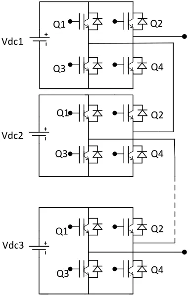
A Cascaded MLI consists of several structures of S H-bridge (Single phase full H-bridge) inverters. Where value of
S depends on level of inverter, for 2S+1 level of inverter S
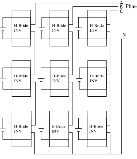
number of H-bridge inverters is required. Fig. 1 shows the structure of single-phase cascaded 7-Level inverter with 3 H-bridges and Fig. 2 shows the 3-phase model of 7-level inverter [11]. Each individual inverter can generate three different voltage output +VRdcR, 0, -VRdcR by connecting dc
input to ac source side by combinations of four active switches SR1R,R RSR2R, SR3R and SR4R. Switching sequence for
various voltage levels is shown in Table 1.
Table 1: Switching sequence of 7-level cascaded multilevel inverter
0B
Voltage level
1st H-bridge 2nd H-bridge 3rd H-bridge
3VRdc SR1R, SR4 S1RR, SR4 SR1R, SR4
2VR
dc SR
1R, SR
4 SR
1R, SR
4 SR
4R, DR
3
VRdc SR1R, SR4 SR4R, DR3 SR4R, DR3
0 Off Off Off
-VR
dc SR
3R, DR
4 SR
3R, DR
4 SR
2R, SR
3
-2VRdc SR3R, DR4 S2RR, SR3 SR2R, SR3
-3VR
dc SR
2R, SR
3 SR
2R, SR
3 SR
2R, SR
3
Here, VRdc1R = VRdc2R = VRdc3R = VRdcR. The output voltage of
cascaded multilevel inverter is equal to sum of the output voltages of the individual bridges and can be controlled to produce a staircase waveform. The advantage of this topology of MLI is that the modulation, control and protection requirements of each bridge are modular.
Vdc1
Vdc2
Vdc3
Q1
Q2
Q3
Q1
Q3
Q1
Q3
Q4
Q2
Q4
Q2
Q4
Fig. 1 Single phase cascaded MLI
3. Analysis of Multilevel Inverter
Fig. 3 shows the typical stepped waveform of the output phase voltage of a 7-level inverter with 3 equal dc sources. Assuming the symmetrical waveform only three angles are required to determine the full waveform αR1R, αR2R and αR3R.
Where, αR1R, αR2R and αR3 Rare the switching angles of
seven-level MLI.
Fourier analysis of this waveform yield the expression:
1 2 3
2 2
(cos( ) cos( ) cos( )),
0,
dc n
V
n n n
V nπ α α α
+ +
=
www.ijiset.com
H-Bride INV
H-Bride INV
H-Bride INV
H-Bride INV
H-Bride INV
H-Bride INV
H-Bride INV H-Bride
INV H-Bride
INV
A B C Phase
N
Fig. 2 Three phase structure of cascaded MLI
Owing to quarter wave symmetry in the waveform, the even harmonics are absent and thus only odd harmonics are present [12].
When αR1R, αR2R and αR3 Rare all equal to zero the maximum
possible value of fundamental components is obtained and given by:
1
6 2
(max) Vdc
V
π
= . (2)
Presenting the fundamental component in per unit (p.u.) based on its maximum value [13]
pu 1
1 1 2 3
1
V 1
V = = (cos(α )+cos(α )+cos(α ))
V (max) 3
(3)
Normalised harmonic components is as follows:
1 2 3
1
1
(cos( ) cos( ) cos( ))
(max) 3
n
V
n n n
V = n α + α + α
(4)
Considering the waveform in Fig. 2, the phase-voltage rms is calculated
2 2 0
2
V
rmsv d t
π
ω
π
=
∫
2 1 3 2 3
2
((
) 4(
) 9(
))
2
Vdc
α α
α α
π
α
π
=
−
+
−
+
−
. (5)Π/2 Π 3Π/2 0
3Vdc
-3Vdc Vdc
Vdc
Vdc α1
α2 α3
2Π t
t
t
t
Fig. 3 Stepped waveform for cascaded MLI
Additionally, in per unit
1(max)
pu rms
rms V V
V
=
2 1 3 2 3
( ) 4( ) 9( )
36 2
π α α α α π α
= − + − + −
. (6)
THD is defined as the ratio of sum of all harmonic components rms value to the rms value of fundamental component and is expressed as:
2 2
1 (THD)
n n p
V
V
∞
=
=
∑
. (7)Substituting V1 and V in (7) by (3) and (6), the following analytical expression is obtained for the phase-voltage THD:
2 1 3 2 3
2
1 2 3
( ) 4( ) 9( )
2
(THD) 1
4 (cos( ) cos( ) cos( ))
p
π
α α α α α
π
α α α
− + − + −
= −
+ +
4. Harmonic Elimination
The number of harmonics which can be eliminated from the output phase voltage of inverter is (S - 1). For example to eliminate the 7P
th
P
order harmonic from seven-level inverter, Eq. (8) must be satisfied. The elimination of triple harmonics is not necessary as these are eliminated automatically from three-phase system [14].
1 2 3
1 2 3
1 2 3
cos( ) cos( ) cos( )
cos(5 ) cos(5 ) cos(5 ) 0
cos(7 ) cos(7 ) cos(7 ) 0
m
α α α
α α α
α α α
+ + =
+ + =
+ + =
(9)
Where switching angles αR1 Rto αR3R must satisfy the following
conditions:
1 2 3
0
2 π
α α α
< < < < (10)
And the modulation index M is defined from m. M=m/s, where s is the number of switching angles. Here, s = 3.
5. Particle Swarm Optimization
The PSO is a population based optimization technique which was originally developed by Kennedy and Eberhart in 1995 [15]. It is a stochastic search method for optimization problem, inspired by the behaviour of swarms such as schools of fish and flocks of birds. Every individual in the swarm is called as particles. PSO can be easily implemented, simple in concept and is an effective techniques when compared to other algorithms such as genetic algorithms (GA) and other iterative techniques.
PSO basically consists of two primary operators: Velocity vector and Position vector. During each iteration each particle searches for the optimal solution and accelerated to the particles global best position and the previously found best position, by comparing itself with the best position it has attained. At each generation a new velocity vector value is generated based on its present velocity, the distance from its previous best position and knowledge of global best position. All these particles move in multidimensional search and keep updating itself to find best solution (fitness). This fitness value decide the gbest
(global best position) and pbest (local best position). The velocity and position vectors of PSO are shown below:
1 1( ) 2(gbest X )
i i i i i i
V+ =WV+alpha rand pbest× −X +beta rand× −
(11)
1 1
Xi+ =Xi+Vi+ (12)
Where, alpha and beta are the cogitative factors, randR1R
and randR2Ris the random numbers between 0 and 1, W is
the inertia weight to guarantee the speed of convergence and defined as:
max
max min min
max iter
( ) iter
W W W W
iter
−
= − × + (13)
6. PSO Algorithm for THD Minimization
Let
α
i=
[
α α α
i1,
i2...
is]
be the initial trial vector of iPth
P
particle of the swarm to be evolved. The elements of αRiR are
the solution of the harmonic minimization problem. The step-by-step by procedure to solve THD minimization problem using PSO is given as follows:
STEP 1: Get initial data for particles such as population size n, the maximum iteration count etc.
STEP 2: Generate initial conditions for each particle. Each particle position in the swarm is randomly initialized between 0 and 𝜋/2 according to Eq. (9); similarly the velocity vector of particle is initialized randomly from -VRmaxR to VRmaxR based on the lower and upper bounds of the
particle. The current searching point is set to pbest for each particle.
STEP 3: Now, for each particle the fitness value is calculated by using the objective function. The THD Eq. (7) is considered to be the objective function. To reduce the overall THD in output voltage waveform, the objective function has to be minimized with the constraints.
Minimise
2
3,5,7 1 2
1
( ) ( , ,... )
m n n m
V
F F
V
α = α α α = =
∑
Subject to:
(
)
1 2
0<α α< < <... αm< π/ 2
1
5 1
7 2 ;
;
;
V m V V
ε ε
= ≤ ≤
(14)
According to Eq. (9) value of VR1R,RRVR5R, VR7 Rare obtained.
www.ijiset.com
Start
Input data to system: n, alpha, beta, gama, time,
LB, UB
Initialize position of particles
αi = [αi1, αi2, αi3] by
randome values in between [0 , 1] { i=1, 2, … ,n}
For each particle calculate fitness
F(
α): objective function
Minimize fitness function F(
α)
Subject to: V1 = 3m, V5
≤ €1, V7 ≤ €2
Find pbest and gbest of each particle
Move each particle to new position and velocity
By comparing it to previously found best postition
Check the termination criteria
End
Output: gbest(
α1, α2, α3 ), F(α)
No
Yes
Fig. 4 Flow chart for PSO algorithm
STEP 4: Each particle of the swarm moves to new position and velocity, according to Eq. (11), (12) based on the pbest and gbest of the system, by updating itself. It also updated the personal best (pbest) if the current position is better than the previous position.
STEP 5: Check for the termination criteria. If the iteration count reaches the maximum iteration, stop; else, go back to step (2).
7. Results
By using PSO method, all possible solution sets for a five and seven level cascaded multilevel inverters are computed and a complete analysis is presented in following paragraphs. Switching angles (αR1R, αR2R, αR3R) are
taken in range of 0P
0
P
to 90P
0
P
. The modulation index value is varies for the linear range from 0.1 to 0.95.
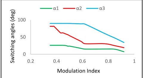
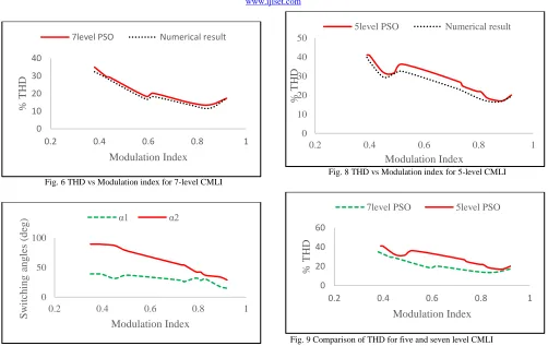
7.1 7-Level CMLI
For seven level cascaded inverter it is required to eliminate the 5P
th
P
and 7P
th
P
order harmonics and get the minimization in total harmonic distortion. The Fig.5 shows the switching angles sets and Fig.6 shows the corresponding least THD for various modulation indices from both numerical method and PSO for 7-level. It can be seen from Fig. 6 that THD is minimum at range 0.7 to 0.8 of modulation index.
7.2 5-Level CMLI
For five level it is required to eliminate the 5P
th
P
harmonics. The Fig.7 shows the switching angles sets and Fig.8 shows the corresponding least THD for various modulation indices from both numerical method and PSO for 5-level. Fig. 9 compares the THD for five and seven level CMLI for same modulation index.
Fig. 5 Switching angles vs Modulation index for 7-level CMLI
0 50 100
0.2 0.4 0.6 0.8 1
Sw
itch
in
g a
ngl
es
(d
eg)
ModulationIndex
Fig. 6 THD vs Modulation index for 7-level CMLI
Fig. 7 Switching angles vs Modulation index for 5-level CMLI
Fig. 8 THD vs Modulation index for 5-level CMLI
Fig. 9 Comparison of THD for five and seven level CMLI
Table 2: Comparison of THD obtained from PSO and numerical method in case of 7-level CMLI
Switching angles in degrees %THD
MI
α1 (PSO)
α1 (Numerical
method)
α2 (PSO)
α2 (Numerical
method)
α3 (PSO)
α3 (Numerical
method)
(PSO) (Numerical method)
0.38 26.2335 19.0911 81.3055 78.8137 89.9427 89.9427 35.00 32.39 0.43 26.2335 18.1949 62.5671 70.184 89.9427 89.9427 29.45 28.90 0.44 26.2335 18.0105 62.4589 68.4077 89.9427 89.9427 29.40 27.97 0.59 17.1627 11.7628 37.3804 37.8145 88.8593 89.9427 18.53 16.90 0.62 15.1922 11.4783 30.89 36.7743 87.8914 85.4689 20.20 18.32 0.77 15.3642 10.2631 30.8573 31.7883 60.8373 61.5755 14.87 13.62 0.85 14.779 8.5061 25.0833 26.6197 47.3599 48.1641 13.62 11.66 0.92 7.5197 6.2796 19.3351 19.7798 34.4113 34.4115 17.34 17.29
Table 3: Comparison of THD obtained from PSO and numerical method in case of 5-level CMLI
Switching angles in degrees %THD
MI
α1 (PSO)
α1 (Numerical
method)
α2 (PSO)
α2 (Numerical
method)
(PSO) (Numerical method)
0.39 39.2299 38.9222 89.427 89.8854 41.08 39.82 0.4 38.54 37.0605 88.9785 89.8854 40.8 37.58 0.52 36.7886 19.4384 76.1637 84.4336 36.27 32.54 0.74 25.9769 16.4636 54.477 58.6006 24.91 22.29 0.8 33.6128 14.9836 39.8967 50.6541 21.92 18.37 0.92 14.9615 9.9364 29.0849 31.2403 20.07 19.47
0 10 20 30 40
0.2 0.4 0.6 0.8 1
% T
H
D
Modulation Index
7level PSO Numerical result
0 50 100
0.2 0.4 0.6 0.8 1
S
w
it
chi
ng
angl
es
(
d
eg)
Modulation Index
α1 α2
0 10 20 30 40 50
0.2 0.4 0.6 0.8 1
% T
H
D
Modulation Index
5level PSO Numerical result
0 20 40 60
0.2 0.4 0.6 0.8 1
% T
H
D
Modulation Index
www.ijiset.com
8. Validation of Results
The results obtained from the PSO algorithm are found very close with those from the numerical method as explained in section 3. Numerical methods are lengthy and tedious to solve. On the other hand PSO converges to optimum value in much less steps. The dotted points in all the graphs shows the numerical solutions which coincides with the PSO solutions validating correctness of PSO. Comparison of PSO and numerical method can be seen in table 2 and table 3.
9. Conclusion
In this paper, application of PSO algorithm is investigated for reduction in THD of CMLI. The simulation is carried out for five and seven level inverter to eliminate harmonics using PSO. PSO converges faster and gives results very close to numerical method. From the result, we can observe that THD is much reduced for 7-level inverter as compared to 5-level. Also, between the modulation indexes in the range of 0.7 to 0.8, the magnitudes of 5P
th
P
and 7P
th
P
harmonics are less. This work can be further extended by increasing the level of CMLI, thereby increasing the number of switching angles. As switching angles are increased, more number of harmonics can be reduced.
References
[1] L.M. Tolbert, F.Z. Peng, T.G. Habetler: “Multilevel converters for large electric drives”, IEEE Trans. Ind. Appl., 1999, 35, (1), pp. 36–44
[2] M. Tarafdar Hagh, H. Taghizadeh and K. Razi, "Harmonic Minimization in Multilevel Inverters Using Modified Species-Based Particle Swarm Optimization," in IEEE Transactions on Power Electronics, vol. 24, no. 10, pp. 2259-2267, Oct. 2009.
[3] J. Rodriguez, Jih-Sheng Lai and Fang Zheng Peng, "Multilevel inverters: a survey of topologies, controls, and applications," in0T0T16TIEEE Transactions on Industrial
Electronics16T, vol. 49, no. 4, pp. 724-738, Aug 2002.
[4] C. K. Duffey and R. P. Stratford, "Update of harmonic standard IEEE-519-IEEE Recommended Practices and Requirements for Harmonic Control in Electric Power Systems,"0T0T16TIndustry Applications Society Annual Meeting,
1989., Conference Record of the 1989 IEEE16T, San Diego,
CA, USA, 1989, pp. 1618-1624 vol.2.
[5] D. G_ Holmes and T. A. Lipo, Pulse Width Modulation for Power Converters. Piscataway, NJ: IEEE Press, 2003. [6] H. S_ Patel and R. G. Hoft, "Generalized harmonic
Elimination and voltage control in thyristor inverters: Part IIVoltage control technique, “IEEE Trans. Ind. Appl., vol. IA-lO, no_ 5, pp_ 666-673, Sep./Oct. 1974.
[7] J. N. Chiasson, L. M. Tolbert, K. J. McKenzie, and Z. Du, "Real-time computer control of a multilevel converter using the mathematical theory of resultant," Math. Comput. Simul. vol.63, no. 3-5, pp. 197-208, 2003.
[8] B. Ozpineci, L. M. Tolbert, and J. N. Chiasson, "Harmonic optimization of multilevel converters using genetic algorithms," IEEE Power Electron. Lett., vol. 3, no. 3, pp. 92-95, Sep. 2005.
[9] T. Jeevabharathi and V. Padmathilagam, "Harmonic elimination of Cascaded Multilevel Inverters Using Particle Swarm Optimization,"0T0T16TComputing, Electronics and
Electrical Technologies (ICCEET), 2012 International Conference on16T, Kumaracoil, 2012, pp. 301-306.
[10]H. Taghizadeh and M. Tarafdar Hagh, "Harmonic Elimination of Cascade Multilevel Inverters with Nonequal DC Sources Using Particle Swarm Optimization," in0T0T16TIEEE
Transactions on Industrial Electronics16T, vol. 57, no. 11, pp.
3678-3684, Nov. 2010.
[11]W. Razia Sultana, Sarat Kumar Sahoo, S. Prabhakar Karthikeyan, I. Jacob Raglend, Pasam Harsha Vardhan Reddy and Gangireddy Taraka Rajasekhar Reddy, 25TArtificial
Intelligence and Evolutionary Algorithms in Engineering Systems25T, 40TVol. 324, 40TSpringer India, 2015.
[12]N. Mohan, T.M. Undeland, W.P. Robbins: “Power electronics: converters, applications and design,”Wiley, New York, 2003, 3rd edn.
[13]N. Yousefpoor, S. H. Fathi, N. Farokhnia and H. A. Abyaneh, "THD Minimization Applied Directly on the Line-to-Line Voltage of Multilevel Inverters," in0T0T16TIEEE
Transactions on Industrial Electronics16T, vol. 59, no. 1, pp.
373-380, Jan. 2012.
[14]R. N. Ray, D. Chatterjee and S. K. Goswami, "Harmonics elimination in a multilevel inverter using the particle swarm optimisation technique," in0T0T16TIET Power Electronics16T, vol. 2,
no. 6, pp. 646-652, Nov. 2009.
[15]J. Kennedy and R. Eberhart, “Particle swarm optimization,” in Proc. IEEE Int. Conf. Neural Netw., 1995, vol. 4, pp. 1942–1948.
Shruti Garg received the B. Tech degree in Electrical and Electronics
Engineering from RGPV, Bhopal and at present she is pursuing M.Tech in Power Electronics and Electrical Drives at Rajasthan Technical University, Kota. Her research interests include Power Electronics, Multilevel Converters and Renewable Energy Technology.
A. K. Sharma received the B. E. (Hons.) degree in Electrical
Engineering from M. B. M. Engineering College, Jodhpur and M. E. with specialization in Power Apparatus in Electric Drives from University of Roorkee (Presently I. I. T. Roorkee) in 1986 and 1993. Presently he is Associate Professor in Department of Electrical Engineering, University College of Engineering, Rajasthan Technical University, Kota. Having 26 years of teaching experience and published/presented 55 research papers in International and National Journals/Conferences. He is life member of Indian Society of Technical Education (ISTE), Indian Society of Lighting Engineers (ISLE). Fellow member of Institution of Engineers (IE-India). His research interests include Power Electronics, Electric Drives, Power Systems, 37Trenewable
energy generation, power quality, Flexible AC Transmission Systems, High Voltage Direct Current transmission systems37T.
Priyanka Yadav received the B.Tech degree in Electrical Engineering