Analysis And Design Of Apartment Building
Full text
Figure
Related documents
Trusted Channel based Migration ● Source platform requests trusted channel to destination –
CONSTITUENTS OF ECONOMIC PERFORMANCE: CONSTITUENTS OF ECONOMIC PERFORMANCE: TO MAKE PRESENT BUISNESS EFFECTIVE. TO MAKE PRESENT
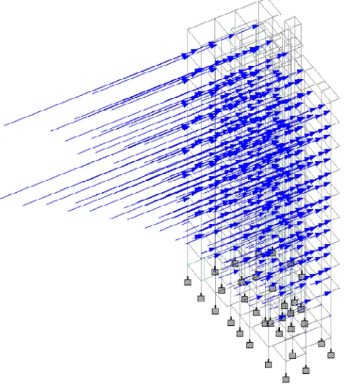
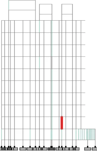
As per IS 875(Part 3):2015Design Loads Other than Earthquake for Buildings and structures, when wind interacts with a building, both positive and negative pressures occur
Research, part of a Special Feature on REDD+ national policy networks: information flows, influence and coalitions for change Multistakeholder environmental governance in action:
You may choose to repay your Car Loan over to 84 months, and also choose our unique fortnightly repayment option which could further save you interest on your loan.. Interest
This Indian Standard was adopted by the Bureau of Indian Standards, after the draft finalized by the Hydraulic Structures Instrumentation Sectional Committee had
The evidence suggests that further reductions in tariffs on forest products are likely to generate only very modest increases in worldwide trade and production, and thus the
The increase genes transcription that describe the response of the p53 gene to Doxorubicin induces DNA damage that causes cell cycle break ( Zhang, 2014 ). Furthermore,
