DEVELOPING PLC BASED GANTRY ROBOT USING POSITIONING SERVO DRIVE WITH PROFIBUS – DP COMMUNICATION PROTOCOL
YASIR AMZAD ALI BIN MOHD YASEEN
A project report submitted in partial fulfillment of the requirement for the award of the degree of
Master of Engineering (Electrical – Mechatronics & Automatic Control)
Faculty of Electrical Engineering Universiti Teknologi Malaysia
iii
Dedicated to my beloved wife Dr Rokiah Binti Khalid
Son, Yasir Adham Ali
Parents ,
iv
ACKNOWLEDGEMENT
In preparing this thesis, I was in contact with many people, researchers, academicians, and engineers. They have contributed towards my understanding and thoughts. In particular, I would like to acknowledge and express my sincere appreciation to my main thesis supervisor, Dr Hazlina Selamat, for encouragement, guidance, critics and friendship. His readiness to help and valuable suggestions were highly appreciated towards to meeting the project objective.
v
ABSTRACT
vi
ABSTRAK
vii
TABLE OF CONTENTS
CHAPTER TITLE PAGE
DECLARATION ii
DEDICATION iii
ACKNOWLEDGEMENTS iv
ABSTRACT v
ABSTRAK vi
TABLE OF CONTENTS vii
LIST OF TABLES xi
LIST OF FIGURES xii
LIST OF ABBREVIATIONS xv
1 INTRODUCTION
1.1 Project Introduction 1 1.2 Project Objective 4
1.3 Scope Of Project 4
1.4 Organization Of Thesis 5
2 LITERATURE REVIEW
2.1 Gantry Robot 6
viii
2.2.2 PLC Features 8
2.2.3 System Scales 9
2.2.4 User Interface 9
2.2.5 Communication 10
2.2.6 PLC Compared With Other Control Systems 10 2.2.7 Digital and Analogue Signal 12
2.2.8 Programming Language 13
2.2.9 Siemens PLC 14
2.3 Profibus Communication Protocol 16 2.3.1 Profibus Introduction 16 2.3.2 Profibus Origin 18 2.3.3 Advantages Profibus Compare Other Fieldbuses 18
2.4 Servo Drive 19
2.4.1 Introduction To Digital Servo Drive 19 2.4.2 Lenze 9300 Positioning Servo Drive 20
3 PROJECT BACKGROUND
3.1 Previous Control System for ABB Robot 22 3.2 Problem with Previous ABB Gantry System 27
3.2.1 Obsolete Parts 27
3.2.2 No Local Support Available For Robot 27 3.2.3 Complicated Control System 28 3.2.4 Homing In Every Movement 29 3.2.5 Unnecessary Tray Scanning Process 29
ix
4 METHODOLOGY
4.1 Introduction 31
4.2 Siemens Programmable Logic Controller 32 4.2.1 Siemens PLC Hardware Configuration 32 4.2.2 Siemens Network Configuration 34 4.2.3 Siemens PLC Program Editor 35 4.2.3.1 Siemens S7-Graph Editor 36
4.2.3.2 Siemens Ladder Diagram (LAD) Editor 39 4.2.3.3 Siemens Statement List (STL) Editor 41 4.3 Siemens Human Machine Interface (HMI) 43 4.4 Global Drive Control 45
5 PLC PROGRAM IMPLIMENTATION
5.1 Introduction 46
5.2 Robot Auto Cycle 48 5.3 Machine Ready, Safety and Error Handling Program 54 5.4 Decision Making Program 58 5.5 Drive Control Program 61 5.6 Execution Of FB3 Programs 63
6 HMI IMPLIMENTATION
6.1 Introduction 67
6.2 Main Screen 68
x
7 DRIVE IMPLIMENTATION
7.1 Introduction 79
7.2 Drive Parameter Configurations 79 7.3 Position Configuration 81 7.4 Drive Program Editor 82
8 RESULTS AND DISCUSSION
8.1 Introduction 84
8.2 Development Stages 85 8.3 Error Recording Program (FC250) 87 8.4 Features Of New Robot Gantry System 88 8.4.1 Simple And Reliable Control System 88 8.4.2 Easy Maintenance & Troubleshooting Process 91 8.4.3 One Touch Button Control Concept 92 8.4.4 Optimize Movement Concept 92 8.4.5 Improved Safety 93
8.4.6 Improved Tray Scanning Process 94 8.4.7 Variable Speed Control To Improve Process Time 95 8.4.8 Touch Screen For The Robot 95
9 CONCLUSION AND RECOMMENDATION
9.1 Conclusion 97
9.2 Recommendation 98
xi
LIST OF TABLES
TABLE NO. TITLE PAGE
xii
LIST OF FIGURES
FIGURE NO. TITLE PAGE
1.1 Gantry Robot Structure 3
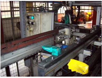
1.2 Loading Station 3
1.3 Unloading Station 4
2.1 Digital Servo Drive 20
3.1 S5 100u CPU 23
3.2 Sanyo Denki Stepper Motor Drive 24 3.3 S5 115u CPU With Input Output Card 25 3.4 Telemeqanique NUM 17.20 CPU 26 3.5 ABB NUM NC Controller Card 26 3.6 BOSH-REXROTH Indramat Servo Drive Axis Module 27 4.1 Hardware Configuration 34 4.2 HMI and PLC Communication Interface 35
4.3 Graph-7 Programs 37
xiii
5.7 Current Running FB Highlighted At Screen 53 5.8 Step Number 10 At FB3 55 5.9 Safety And Error Programs Control’s Flow Chart 56 5.10 Error Message For Emergency Button And Safety Door 56 5.11 Ladder Diagram Check Machine Emergency 57 5.12 Ladder Diagram Check Main Air Pressure 58 5.13 Machine Ready Condition Displayed At Screen 59 5.14 Flow Chart Of Decision Making Program 60 5.15 Profibus Control Program For X-Axis 61 5.16 Flow Chart For Drive Control Programs 62 5.17 Error Message Related Drives At Touch Screen 63 5.18 Ladder Diagram Check Priority For FB3 64 5.19 Flow Chart FB3 Functions 66
6.1 Main Screen 68
6.2 Auto Cycle Screen 69
6.3 Actual Position And Speed Value 70
6.4 Tray Status 70
6.5 Start Button Hidden 71 6.6 Start Button Displayed 71
6.7 Machine Ready Status 71
6,8 Sequence Status 72
6.9 Set Axis Speed Parameter 73 6.10 Set Maximum Tray Value 73 6.11 Semi Auto Cycle Screen 74 6.12 Semi Auto Mode Go To Location 75 6.13 Semi Auto Part Program 75 6.14 Manual Cycle Screen 76 6.15 System Diagnostic Screen 77 6.16 Teaching Mode Screen 78 7.1 Motor Data Parameter 80 7.2 Position Configuration 81
7.3 FB Editor Software 83
xiv
xv
LIST OF ABBREVIATIONS
PLC - Programmable Logic Controller NC - Numeric Controller
PWM - Pulse Width Modulation CPU - Central Processing Unit IO - Input Output
MS-DOS - Microsoft Disk Operating System MTC - Machine Tool Control
CHAPTER 1
INTRODUCTION
1.1 Project Introduction
SKF Bearing Industries Sdn Bhd is world-class manufacturer of bearings employing the most modern technology in the industry. Plant is located in Nilai and supplies the world with quality bearings.
In order to manufacture Cylindrical Roller Bearing (SRB) , heat treatment process for the roller is one of the crucial and importance process. Every minute thousands of rollers need to supply to the furnace to undergo heat treatment process.
2
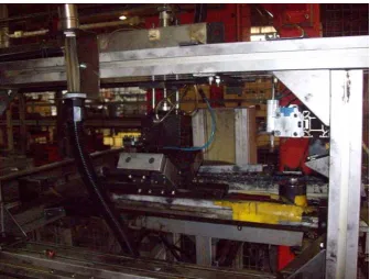
Second system is unloading system. After the roller finished heat treatment process, robot will unload the pallet from furnace and deliver the tray to unloading station. Unloading station will distribute the roller for grinding process.
Previous gantry robot system is using ABB automation control design. This robot’s design is outdated & not efficient in this new era. The ABB robot is using CNC controller and using three separate PLCs to control loading and unloading station.
The idea is to replace old fashion of automation control to new , fast , reliable , user friendly , easy to troubleshoot & easy to maintain gantry robot automation system.
This project is to upgrade the old gantry robot system to cheap & reliable robot control system using PLC control system. After I had done some research and studies, I had found out the simplest & much reliable robot design using PLC & positioning servo drive.
3
Figure 1.1 : Gantry Robot Structure
4
Figure 1.3 : Unloading Station
1.2 Project Objective
Project objective is to develop complete control system for 3 axis gantry robot using Siemens s7 PLC, Lenze positioning servo drive, Siemens touch screen and these devises is communicate via Profibus - DP protocol.
1.3 Scope Of Project
5
Flexible 2008 and configuring and writing Lenze drive program Global Positioning Drive software.
1.4 Organization of Thesis
This thesis consists of eight chapters. Chapter 1 provides preliminaries studies on the current scenarios of this project. In Chapter 2, literatures on devices and technology that used in this project will be discussed briefly.
Chapter 3 describes and briefs the theoretical background of the project. In this chapter, will discussed comparison between previous robot system and future robot system will be discussed.
Chapter 4 will discuss methodology that used in order to complete these projects. In this chapter, software and hardware that used for the projects will be discussed briefly. Meanwhile in Chapter 5, PLC program implementation will be discussed. This chapter will go thorough entire function that developed in order to complete this project.
Chapter 6 will discuss about HMI implementation. In this chapter HMI design and development will be discussed. Chapters 7 will focus on drive implementation. In this chapter drive configuration and programming will be discussed briefly.
99
REFERENCES
1. Erickson, K. T. (2005). Programmable Logic Controllers: An emphasis on design and application. Dogwood Valley Press, LLC, 1604 Lincoln Lane Rolla, MO, USA.
2. Bolton, w., Programmable Logic Controllers: An Introduction, Heinemann, 1997
3. Clements-Jewery, K., Jeffcoat, W., The PLC Workbook; Programmable Logic Controllers made easy , Prentice Hall, 1996.
4. Siemens AG. S7-400 and m7-400 programmable controllers - hardware and installation., September 2004. URL
http://www.siemens.co.jp/simatic/japan/as/plc/data/400/424ish\_e.pdf.
5. Fieldbus technology, June 2009. URL
http://murray.newcastle.edu.au/users/students/1999/c9518176/fieldbuste
6. Profibus - profibus & profinet., June 2009. URL http://www.profibus.com/profibus.html.
7 Lenze Drive Configuration Manual , June 2009 .URL
http://www.lenze.com/lenze.com_en_active/040_Services/060_Application_
Knowledge_Base/Application_Knowledge_Base.com.jsp?cid=0b0164e0800