University of Windsor University of Windsor
Scholarship at UWindsor
Scholarship at UWindsor
Electronic Theses and Dissertations Theses, Dissertations, and Major Papers
2010
Collective cluster-based map merging in multi robot SLAM
Collective cluster-based map merging in multi robot SLAM
Ahmad Soleimani
University of Windsor
Follow this and additional works at: https://scholar.uwindsor.ca/etd
Recommended Citation Recommended Citation
Soleimani, Ahmad, "Collective cluster-based map merging in multi robot SLAM" (2010). Electronic Theses and Dissertations. 7963.
https://scholar.uwindsor.ca/etd/7963
This online database contains the full-text of PhD dissertations and Masters’ theses of University of Windsor students from 1954 forward. These documents are made available for personal study and research purposes only, in accordance with the Canadian Copyright Act and the Creative Commons license—CC BY-NC-ND (Attribution, Non-Commercial, No Derivative Works). Under this license, works must always be attributed to the copyright holder (original author), cannot be used for any commercial purposes, and may not be altered. Any other use would require the permission of the copyright holder. Students may inquire about withdrawing their dissertation and/or thesis from this database. For additional inquiries, please contact the repository administrator via email
COLLECTIVE CLUSTER-BASED MAP MERGING IN MULTI ROBOT SLAM
by
Ahmad Soleimani
A Thesis
Submitted to the Faculty of Graduate Studies through Computer Science
in Partial Fulfillment of the Requirements for the Degree of Master of Science at the
University of Windsor
Windsor, Ontario, Canada
2010
1*1
Library and Archives CanadaPublished Heritage Branch
395 Wellington Street Ottawa ON K1A 0N4 Canada
Bibliotheque et Archives Canada
Direction du
Patrimoine de I'edition
395, rue Wellington Ottawa ON K1A 0N4 Canada
Your die Votre reference ISBN: 978-0-494-62734-1 Our file Notre r6f6rence ISBN: 978-0-494-62734-1
NOTICE: AVIS:
The author has granted a
non-exclusive license allowing Library and Archives Canada to reproduce, publish, archive, preserve, conserve, communicate to the public by
telecommunication or on the Internet, loan, distribute and sell theses
worldwide, for commercial or non-commercial purposes, in microform, paper, electronic and/or any other formats.
L'auteur a accorde une licence non exclusive permettant a la Bibliotheque et Archives Canada de reproduire, publier, archiver, sauvegarder, conserver, transmettre au public par telecommunication ou par I'lnternet, preter, distribuer et vendre des theses partout dans le monde, a des fins commerciales ou autres, sur support microforme, papier, electronique et/ou autres formats.
The author retains copyright ownership and moral rights in this thesis. Neither the thesis nor substantial extracts from it may be printed or otherwise reproduced without the author's permission.
L'auteur conserve la propriete du droit d'auteur et des droits moraux qui protege cette these. Ni la these ni des extraits substantiels de celle-ci ne doivent etre imprimes ou autrement
reproduits sans son autorisation.
In compliance with the Canadian Privacy Act some supporting forms may have been removed from this thesis.
While these forms may be included in the document page count, their removal does not represent any loss of content from the thesis.
Conformement a la loi canadienne sur la protection de la vie privee, quelques formulaires secondaires ont ete enleves de cette these.
Bien que ces formulaires aient inclus dans la pagination, il n'y aura aucun contenu manquant.
Author's Declaration of Originality
I hereby certify that I am the sole author of this thesis and that no part of this Thesis has been published or submitted for publication.
I certify that, to the best of my knowledge, my thesis does not infringe upon anyone copyright nor violate any proprietary rights and that any ideas, techniques, quotations, or any other material from the work of other people included in my thesis, published or otherwise, are fully acknowledged in accordance with the standard referencing practices. Furthermore, to the extent that I have included copyrighted material that surpasses the bounds of fair dealing within the meaning of the Canada Copyright Act, I certify that I have obtained a written permission from the copyright owner(s) to include such material(s) in my thesis and have included copies of such copyright clearances to my appendix.
Abstract
New challenges arise with multi-robotics, while information integration is among the most important problems need to be solved in this field. For mobile robots, information integration usually refers to map merging. Map merging is the process of combining partial maps constructed by individual robots in order to build a global map of the environment.
Dedication
This thesis is dedicated to my beloved parents whom I owe every moment
of joy and success in my life.
Also, this thesis is dedicated to my loyal wife, Zeinab who did not hesitate
to put most of the family responsibilities on her shoulders during my
studies while at the same time the smile never disappeared from her face.
Finally this thesis is dedicated to my lovely twin Angels, Yasamin and
Malaak whom their "dadi" calls and "jump for hugging" used to take out
Acknowledgements
First of all, I would like to thank my supervisor, Dr. Dan Wu, for his
continuous assistance and advices, and also for his encouragement and
understanding during the entire period of Master study, especially this
thesis work.
Besides, I would also like to thank my external reader, Dr. Chunhong
Chen, my internal reader, Dr. Jessica Chen, and my thesis committee
chair, Dr. for spending their precious time to review this thesis and putting
TABLE OF CONTENTS
AUTHOR'S DECLARATION OF ORIGINALITY iii
ABSTRACT iv
DEDICATION v
ACKNOWLEDGEMENTS vi
LIST OF TABLES ix
LIST OF FIGURES x
LIST OF ABBREVIATIONS xi
CHAPTERS
1. INTRODUCTION 1
2. BACKGROUND STUDY 4
2.1 Robot mapping 4 2.2 Map representation 5
2.1.1 Occupancy grid maps 5
2.1.2 Topological maps 6
2.3 Robot localization 7
2.3 SLAM 10
3. MAP MERGING 13
3.1 Overview 13 3.2 Classification and literature review 14
3.2.1 Odometry information 1 5
3.2.2 Robots intercommunication 18
4. COLLECTIVE CLUSTER-BASED MAP MERGING IN MULTI-ROBOT
SLAM 22
4.1 Overview 22 4.2 Overlap 25 4.3 Notation and problem definition 26
4.4 How good the transformation is? 27
4.5 Failure detection 31
5. IMPLEMENTATION AND EXPERIMENTAL RESULTS 34
5.1 Implementation details 34
5.1.1 Why MRDS? 3 4
5.1.2 Robot 3 5
5.1.3 Mapping environment 3 6
5.1.4 Programming platform 3 8
5.2 Simulation experiments 38
5.2.1 Gaussian pdf parameters 3 9
5.2.2 Mapping experiments 4 2
5.2.2.1 Areal mapping experiments 4 2
5.2.2.2 Area2 mapping experiments 4 5
5.3 Analysis and discussion 49
6. CONCLUSION AND FUTURE WORK 52
6.1 Conclusion 52 6.2 Limitations of the proposed method 53
6.3 Future work 54
REFERENCES 55
APPENDIX A 61
LIST OF TABLES
2.1 General algorithm for Bayes filtering 9 4.1 Algorithm 1, pseudo-code for the proposed method of Clustered
map merging in multi-robot SLAM 33 5.1 Average Weighted throughput for transformations with different values
of Gaussian distribution parameters 40 5.2 Areal mapping time for single Robotl and Robot2 individually 42
5.3 Areal mapping statistics using basic multi-robot SLAM implementation ....43 5.4 Areal mapping statistics using the proposed enhancement of
multi-robot SLAM method 43 5.5 Area2 mapping time for single Robotl and Robot2 46
5.6 Area2 mapping statistics using basic Multi-robot SLAM implementation 46 5.7 Area2 mapping statistics using proposed Multi-robot SLAM
LIST OF FIGURES
2.1 Occupancy grid map 6 2.2 Topological representation of an indoor office area 7
2.3 Bayes filter rule and posterior probability over Poses and partial map 9
2.4 General formula of SLAM using odometry data 12 4.1 Mapping robots do not fall in the sensor range of each other 24
4.2 Mapping robots fall within the communication range of their sensors 25 4.3 Transformation: translation and rotation to establish maximum overlap 26 4.4 SLAM proposed improvement of in-advance pair-wise localization 28 4.5 Initial grid represented map along with its equivalent grid matrix 29
4.6 Initial grid matrix with its distance map matrix 30 4.7 Initial grid map of a square shape area along with its distance map 30
5.1 Pioneer3DX mobile robot with its sensors 35 5.2 Areal, first mapping area, an indoor office area with uneven walls 37
5.3 Area2, the second mapping area, an office area with different sized rooms
and corridors 38 5.4 Average Throughput for different values of a 41
5.5 An example of successful partial map merging in Areal 45 5.6 An example of unsuccessful map transformation in Areal 45 5.7 An example of successful transformation and map merging process in
Area2 48 5.8 Area2 final map drawn by collective mapping task of Robotl and
Robot2 48 5.9 Overall mapping time for Areal and Area2 using single mapping robot,
t
LIST OF ABBREVIATIONS
Al Artificial Intelligence EKF Extended Kalman Filter IR Infra Red
LRF Laser Range Finder
MRDS Microsoft Robotics Developer Studio MVS Microsoft Visual studio
PDF Probability Distribution Function RBF Recursive Bayesian Filter
SLAM Simultaneous Localization And Mapping USAR Urban Search and Rescue
Chapter 1
INTRODUCTION
This thesis addresses the problem of map merging in multi-robot environments. Map merging is the process of combining partial maps built by individual members of a team of robots or multiple runs of a single robot in order to obtain the global map of the environment in a shorter time and higher coverage of the mapping area.
Exploring an unknown environment and constructing its map using mobile robots is a well-known problem in the field of Artificial Intelligence (Al) and robotics. It has been studied widely during the last two decades, using a single robot equipped with different kinds of perception sensors and important successes have been achieved [23, 48]. Recently, most of the research in this field has turned to focus on using multiple or team of robots. If fact, multi-robotics is aimed to fulfill the increasingly demand for automation of difficult tasks and high risk missions, such as planetary exploration, scouting, rescue operations in catastrophe conditions, cleaning, etc. In such environments, the complete coverage of the terrain is a result of the integral parts of a multi-robotic mission
its task completely autonomously and independently while there should not be an agent with unique software or hardware features making it vital for the success of the mission [7]. Also, a multi-robot system must benefit from a high scalability level, in which adding a new robot or removing existing one should not require huge amount of reconfiguration and/or restructuring operations [7].
It is evident that the purpose of having a multi-robot system is to have them achieve the assigned task more reliably and in a shorter time. However, the main challenge of such a system is how to put together and effectively combine the data acquired by individual robots. In fact, this is what is called the problem of
map merging in the field of robot mapping. This thesis work is intended to
investigate this problem and it comes up with a considerable enhancement to an existent method of map merging for environment represented by occupancy grids.
In particular, our approach to the problem of map merging is similar to the work of Birk, A. and Carpin, S. [7]. In this work along with some others [10, 12, 35], map merging is based on finding similarities in the grid representation of the local maps built by each individual robot and then by applying geometric transformations, a best match (overlap) between them is being used in the merge process. In other words the target is to find the transformation which provides the maximum overlap between local maps.
(C) will be considered. In this notation, k = a.gridsize is dependant to the grid size of the map. This assumption is being made in order to insure dismissing as much unwanted transformations as possible from our search space, considering the fact that the overlap region is most probably located somewhere around the point of meeting. The results from experiments showed that by applying these improvements we managed to increase the transformation effectiveness (a metric to measure the rate of desired transformations) from 71% in Basic multi-robot SLAM to 86% in our proposed SLAM method.
Chapter 2
BACKGROUND STUDY
This chapter briefly illustrates the relevant topics to robot's map merging problem. It provides the necessary background in order to present our map merging proposed method. Section 2.1 briefly talks about the topic of robot
mapping. Section 2.2 describes occupancy grids and topological maps-the two
most popular methods of map representation in the field of robot mapping. A mobile robot needs to keep track of its location (be localized) in order to perform its assigned duties, a subject covered by Section 2.3. Finally section 2.4 briefly explains the well-known method of Simultaneous localization and mapping (SLAM)
2.1 Robot mapping
"Robot mapping is that branch of one, which deals with the study and application of ability to construct map or floor plan of the environment by the autonomous robot and to localize itself in it" [24]. In fact, for any mobile agent including humans, in order to perform any task or mission which requires relocation, a prerequisite necessity will be to know the distribution of the occupied and non-occupied spaces or in other words, the "map" of the environment. This knowledge enables the mobile agent to perform the assigned tasks appropriately. Therefore if the map of the exploration environment is given and the mobile agent is aware of its position within that map (localized), it can use its sensor readings data along with the motion model of the environment to achieve its goals.
motion model to build a partial or complete map of the environment. Furthermore, this constructed map needs to be properly represented in order to be used effectively by mobile robots.
2.2 Map representation
There are different methods used to represent the maps of the environments. In mobile robotics field, however, two of these representations, occupancy grids and topological, are the most popular methods used for the purpose of robot exploration.
2.1.1 Occupancy grid maps
Occupancy grids are the most popular method used to represent the map of the environment of a mobile robot when there is no prior information about the physical structure of the environment. In this method the environment is represented by a grid of cells in which a cell is either filled (part of an obstacle), empty (part of a free space) or unknown. Each cell holds a probability that the cell is occupied by an object while the attributes of that object (shape, color, etc.) do not make up a concern for the representation process. Grid maps are useful for combining different sensor scans, and even different sensor modalities-Sonar, laser, IR, bump, etc. [47]
extended to support transient obstacles by decrementing the cell values over time. [28]
Figure 2.1 is an example of occupancy grid representation for a simple environment which includes three enclosed objects with uneven surfaces. In this representation, black cells indicate obstacles; white cells indicate free spaces and grey cells show uncertainty status. One of the drawbacks of this representation is the high amount of memory consumption used to store the mapping data, since the size of the map in robot memory is directly related to the size of the environment.
obstacles, white cells represent free spaces and grey cells show uncertainty status [28]
2.1.2 Topological maps
representation for a small office area. In this representation, the nodes of the graph (1 to 18) demonstrate the landmarks while the edges denote the connectivity (reachable paths) between them.
It is evident that the amount of memory space needed to represent a map using this method is much lower than the corresponding grid representation. Therefore, the compactness of this representation beside the ability to embed the non-geometric features used for localization process are the main advantages of this method. However the lack in expressiveness of the robot position in an accurate way makes it inappropriate for the task of mapping where a detailed expression of the environment is needed [28].
Figure 2.2: a topological representation of an indoor office area. In the above graph, each node denotes an individual landmark (from 1 to 18) and each edge denotes the connectivity between two landmarks [28]
2.3 Robot localization
In fact, the main problem of robot localization can be break down into two sub problems of global position estimation and local position tracking [28]. Global position estimation is to specify the position of the robot in a given map and once the robot is localized we need to keep track of the robot position over time. To be able to perform a successful mission, providing both of these capabilities is essential.
There are different approaches to solve the problem of robot localization problem. However, considering the probabilistic nature of this problem which is due to the uncertainty and noise associated with sensor readings and also motion model of mobile robots, it would appear that probabilistic approaches are among the most adequate candidate methods to provide a comprehensive real-time solution to this problem. Therefore, methods based on Bayesian reasoning approach have attracted most of the research in situations where the environment is represented by occupancy grids with no landmarks [13].
The Bayesian model approach provides the general framework for the estimation of the system state (robots poses) in the form of a probability distribution function. In fact, Bayes filter recursively computes the posterior probability over poses and partial map given previous sensor measurements & motion commands. Figure 2.3 illustrates the recursive interaction between the robot pose (jt:t), an observation made by the robot (zt) and a robot motion
command ( ut) all given at time t.
The recursive Bayesian filter (RBF) is a probabilistic framework for state estimation that utilizes the Markov assumption (i.e., past and future measurements are conditionally independent, if the current state is known) [17]. The RBF estimates the posterior belief of the robot position given its prior belief, motion and sensor measurements, and the model of the world (or environment). A belief reflects the robot's internal knowledge about the state of the environment. [47]
incorporating the motion actions and sensor measurements. As shown in Table 2.1, the belief about the robot pose at timet, bel(xt), is calculated from the
belief bel(xt_!) at time t-1, the last motion action ( ut) and the most recent
sensor reading (zt). In fact, this update operation to determine the pose of the
robot is being applied recursively to obtain the belief bel(xt) from the belief
bel(xt-i) which was obtained in a similar process in a previous iteration of the
algorithm.
0 0
Figure 2.3: Boyes filter recursively computes posterior probability over Poses and partial map given previous sensor measurements & motion commands. Here xt stands for a robot pose, z, an observation made by the robot, and u, a robot motion command given at time c. [9]
Algorithm Bayes_filter(faef(xt_i),ut,zt):
for all xt do
bel(xt) =
bel(xt) =
endfor
return bel(xt)
Jp(*t
fP(Zt
| ut,xt_{) bel(xt.
xt) bfl(xt)
- l ) dXf-!
Table 2.1: General algorithm for Bayes filtering [47]. the belief about the robot pose at time t, bel(xt), is calculated from the beliefbel<xt_{) at time t-1, the last motion action ( ut)
and the most recent sensor reading (zt).
the probability distribution function based on the results obtained. This sampling-based localization algorithm is sampling-based on a three step process of prediction, re-sampling and update tasks and will be running continuously until a certain threshold of accuracy as a success indicator is met. (For more information on the algorithm of Monte-Carlo and particle filter approach, refer to [47])
It is clear that in the event of absence of the environment map, the process of robot localization and tracking loses its sense since a localization task is being performed to specify the pose (position and orientation) of a mobile robot over time in a well sketched (mapped) environment. In fact, in real environments the problem of localization and mapping usually appear together when the robot is placed randomly in an unknown area. According to this assumption, a simultaneous task of mapping and localization can provide a one-pass reliable solution for both problems. This approach has attracted a lot of research in the field of robot localization and mapping and established the well-known method of SLAM (Simultaneous Localization And Mapping).
2.4 SLAM
Therefore, the goal of SLAM is to use the environment data (through the sensor readings) to continuously discover the distribution of the free and occupied spaces in the exploration environment (mapping part) while keep updating the belief about the real location of the mobile robot within the local constructed map (localization part). This process is being performed by adding newly observed parts of the environment to the previously visited regions.
In particular, the odometry data measured by the movement of the wheels of the robot feeds the SLAM algorithm with an initial approximation of where the robot might be, and then a correction process using the readings from the robot sensors along with the motion model rules will be applied to that initial approximation to derive an accurate estimate of the real position of the robot within the local map. In fact, since the posterior distribution of the SLAM is related to the current and all previous sensor readings (z1 : t) and also to all but
current motion commands (u0 : t_i), it can be written as p^x1.t,m\z1.t,u0:t_1) in which all time poses of the robot (Xi: t) along with the map (m) have to be
determined.
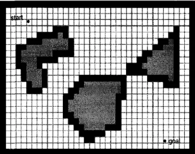
Considering the fact that map m is independent from the motion actions of the robot, the above conditional probability can be expanded to a product of two conditional posteriors of p(Xi: t|zi: t fUo: t-i). V(m\xi-.t>zi:t)- Therefore the problem of simultaneous localization and mapping will be turned into two sub-problems of partial localization and mapping with known poses. Figure 2.4 illustrates the general probability distribution formulation of the SLAM problem and the mutual interaction between the robot pose (A:.), odometry data (ut),
Mapping with o d o m e t r y
poses map observations & movements
A I, / *~
r-~-"
t PO'1-.I I «!:(., «0:t l ) ' P(m I ;':1 : ^ « l : t )
S L A M posterior I
Robot path posterior
Mapping with known poses
Chapter 3
MAP MERGING
The aim of this chapter is to provide the reader with a literature review of the recent important works done in the field of map merging. The first section gives an overview of the map merging problem, while the second section classifies the associated literature and current map merging methods into three groups based on their interaction with the issues of robots odometry, intercommunication and
initial poses.
3.1 Overview
Cooperative exploration and building a reliable model of the environment in multi-robot systems is a key criterion to assure the autonomy of the system [1]. In a typical multi-robot system, the participating robots build maps in their local coordinate systems which need to be transformed into a global coordinate system. The procedure of estimating these transformations and fusing the locally created maps together in order to build a joined global map is known as the map-merging problem. In many approaches the problem is being considered as a search problem by repeatedly proposing candidate transformations and verifying the quality of them. The differences are differentiated by metrics guiding their proposal and verification processes. [1, 39]
new set of challenges and difficulties in robot coordination, inter-communication and data integration.
Data integration deals with the techniques of combining distributed partial information collected by different robots operating in several parts of the environment. Data integration can happen at different levels but in this context, the sub-problem of how to merge local maps built by several robots into a unified global map, forms the essence of the problem. According to [28], this problem of map merging, "Is an interesting and difficult problem, which has not enjoyed the same attention that localization and map building have". During the last few years, this issue has attracted an increasing number of researchers in the field of multi robotics and multi-agent programming and consequently has resulted in developing important practical algorithms and techniques to best deal with this challenge. Map merging plays a crucial role in multi-robot SLAM (Simultaneous Localization and Mapping) and USAR (Urban Search and Rescue) fields.
Approaches to map merging were made from different perspectives and set of assumptions resulted in several techniques and strategies in dealing with this problem. Among these main perspectives are, existence of real time communication between the agents [18, 24], prior partial knowledge about the map of the environment, knowledge about the initial location of participating agents [44, 24], and using of odometry information [40, 33]
3.2 Classification and literature review
Multi-robot systems and multi agent programming are the most recent state-of-the-art topics in the field of Artificial intelligence and robotics. Map merging is the process of building a consistent model of the environment using the data collected by several robots [35]. If the initial positions of the robots are known, map merging becomes a simple extension of a single robot mapping. In contrast, if the robots do not know their relative positions, the problem becomes more difficult; as it has to be determined how and where individual robot perceptions of the environment (local maps) should be integrated into a comprehensive global map. As mentioned before, some assumptions about robots, and also the availability or absence of some important data, play an essential role in specifying the kind of approach and possible solution for the problem of map merging. The following sections describe briefly the classification of map merging techniques based on these criteria.
3.2.1 Odometry information
Odometry is the use of data from the movement of actuators to estimate change in position of the robot over time [24]. The word odometry is composed from the Greek words hodos (meaning "travel", "journey") and metron (meaning "measure").
Whether the robot is wheeled or legged, its position can be estimated through special calculations on the movements of its actuators. In fact, to use odometry effectively, there needs to be an accurate and real time data collection, equipment calibration, and suitable processing resources for storage and analysis of the collected data. Considering map merging, some researchers believe that using odometry in mapping and map merging process can improve the time required and also the accuracy of the final global map.
global map given the data of local maps collected through individual robots. To deal with the problem of errors dependency measurements, Lakaemper et al. [34] suggest using a new map merging process based on geometric local process of line segment merging with a global statistical control. On the other side, in order to prevent running into high dimensionality, they propose using a higher level objects presentation (line segments and generalized polygons) to represent the landmarks of the environment, further more they use a process called Discrete Segment Evolution, that minimizes the number of line segments required to represent the mapped environment. Furthermore, to overcome the problem of correspondence, they propose using a sophisticated shape similarity relation method.
In the work of Leon et al. [35], the process of building a map from the odometry data obtained by multiple robots is being done by using Scan-match technique. For this purpose they have used GMapping and GridSLAM algorithms obtained from OpenSlam.org with some modifications to the original codes and parameters.
Panzieri et al. [40] use the odometry data gathered by multiple robots in a different approach, as they combine topological and occupancy grid map representations in their map merging proposed method. First, an Extended Kalman Filter (EKF) in a SLAM scheme is performed to improve the odometry information and to build a geometric map with specified locations of the beacons and robot poses. Second, considering the fact that fuzzy theory models the sonar reading uncertainties better than a probabilistic approach, they create a Fuzzy Global Map (FGM) using ultrasonic range finders while navigating the environment. Then the FGM can be applied to the estimation to increase the accuracy of the maps by comparing the mapping area with a fuzzy local map (FLM). Finally a special artificial visual perception (FLM vision) of the robot environment is computed from the actual sonar data and used for topological localization.
interrupt the mapping process and resume it at a later time without having to reset the poses of the robots, which gives them a solution for the kidnapped robot problem. With this approach, a three step procedure is being performed in which, first appropriate transformations based on the angles between line segments of the scans are being found, then the related transformation are being evaluated and finally the best found transformation are being applied and the scans to build pairs of scans. To create the final general map, theses pairs of scans need to be merged using special methods.
Carpin [11] ignores the usage of odometry data gathered by participating robots and in turn bases his approach on finding the best transformations (rotations then translations) made on one map to best overlap with the other maps creating the general map of the environment. The transformations are weighted using an "acceptance index" function defined based on the number of matching cells - free or occupied - in the merging maps. To specify the best transformation, a metric is necessary, while in many of works done using this approach, Hough Spectrum analysis is being used to solve the problem of scan matching. Hough transform is being used to detect lines and other geometric curves that can be parameterized with few values. As Hough spectra are one-dimensional signals, cross correlation between two such signals can be used to determine similarities and therefore finding the best overlapping transformations. The main purpose of this paper is to develop a method to perform the task of map merging in the field of urban search and rescue robotics where multiple robots are involved in the search and rescue task. In the begging of this research, the authors mention some of the difficulties related to this kind of problem and summarized them as lack or inaccuracy of reliable odometry information which results in unknown poses of the robots, missing distinguishable landmarks due to the catastrophic scenarios and finally minimal scan overlap of the robots sensor data.
very reliable due to the conditions of the environment. Lakaemper et al. [32] develop a method to perform the task of map merging in the field of urban search and rescue robotics where multiple robots are involved in the search and rescue task. In this method, a sophisticated data structure is being created and then optimized to represent local maps in term of graphs and they use a technique called "Force Field Simulation" (FFS) to perform map merging process. This approach is inspired by simulation of dynamics of rigid bodies in gravitational fields in which the physical laws were replaced by human perception constraints.
3.2.2 Robots intercommunication
It is clear that having a kind of communication between the members of a team of robots exploring the environment can be beneficial to the process of map merging in the sense of cutting the time required for the entire procedure by eliminating some of the redundancy caused by repeated visits of different robots to the same areas of the environment. However, using communication brings to the scene a new set of challenges. Unreliable continuous wireless communication, due to noise and obstacles, data loss and corruption, data consistency, cooperation and coordination of participating robots, are among some of the new issues that arise in such an environment. Therefore some researchers prefer to include complete or partial communication in their approaches to map merging.
different levels of coordination) types. The entire multi robot system is summarized by a graph structure in which the nodes are the navigating robots and the edges represent the current interaction between pairs of robots.
Pan et al. [39], on the other hand use the intercommunication between robots to build a global map of the environment through merging local maps built by multiple robots using a distance transform and an improved genetic algorithm. The idea of using a genetic algorithm in the field of multi robotics is to use the concept of consecutive generation similarities in finding the maximum overlap at which the local maps can be merged at. The idea behind the genetic algorithm is to generate many individual solutions randomly to build an initial population and then to select a portion of the existing population to generate the second generation population through applying a set of genetic operators such as crossover and mutation. This process continues until a specific threshold is met. To overcome the low speed and search deficiency of traditional genetic algorithms, some techniques such as distance transformation and adaptive strategy genetic algorithm can be adopted to enable these algorithms to search and find the best transformations between the constructed local maps to generate the final global map in a reasonable time.
exploration, the size of exploration clusters increases as more robots determine their relative locations, ending in a single cluster of all robots.
In contrast, in the work of Birk and Carpin [7], the robots do not interact with each other while drawing the local maps, the resulted maps then will be merged using a special similarity metric (acceptance indicator) and a stochastic search algorithm. In this approach, a multi stage mapping algorithm is being used in which in the first stage, the robots start building local maps independently and represent them in the form of occupancy grids rather than topological- to overcome the issues related to feature based maps, while in the second stage a stochastic transformations search algorithm (Adaptive Random Walk) is used to perform an initial pair-wise merge process based on the highest degree of overlap (maximum acceptance indicator) for every pair of the local maps. Finally, an optimization heuristic function will rearrange and realign the attached portions of the global map.
3.2.3 Robots initial positions
The existence of prior knowledge about the initial positions of the navigating robots simplifies and smoothes the process of mapping and map merging by a large degree. In fact, such an assumption eliminates the localization part of the problem; however, it limits the scenarios that can be handled by such a navigation strategy due to its unrealistic hypothesis. A one real-life case of such a condition is where all robots start from the same point.
Howard et al. [23] assume that all robots start from the same point. They extend the work of Hahnel, et al. [2003] in which a single-robot Rao-Blackwellized particle filter was considered and tries to generalize it to handle multi-robot case in which the initial position of the participating robots is known. In this approach, an approximation is being used to solve the more realistic problem of multiple robots in which the initial position of the robots is not known (robots start from widely spread locations) and also to integrate observations collected before robots encounter each other using the notion of virtual robot travelling backward in time.
In contrast, in the work of Wang et al. [48], the problem of multi robot localization and mapping is being covered when there is no information about the initial locations of the robots at all. They reformulate the problem of multi-robot SLAM into a mapping static estimation problem by having the locally built maps being fused into a jointly maintained global map through decoupled SLAM (D-SLAM) framework. Since the exploring robots are not aware of their initial locations, they start navigating and building a local map by using a traditional extended Kalman filter algorithm and the resulted local maps will be uncorrelated to each other. The alignment of these local maps is being performed by special algorithm inspired by the method of medical image registration and the test of joint compatibility. At specific intervals, the D-SLAM framework will be used to fuse them into a global map.
Chapter 4
COLLECTIVE CLUSTER-BASED MAP MERGING IN
MULTI-ROBOT SLAM
This chapter is intended to introduce our proposed method to solve the problem of map merging in a multi-robot environment. In section 4.1, an overview of developed method along with a brief description about the possible communication interactions between a pair of robots is provided. Section 4.2 illustrates the overlap implication in the field of map merging. The formal formulation of the map merging problem along with our grids similarity and transformations based approach is presented in Sections 4.3 and 4.4. Finally in Section 4.5, a mechanism for failure detection in our method is introduced.
4.1 Overview
Considering the different approaches to solve the problem of map merging in multi-robot SLAM, our proposed method is based on grid image similarity approach presented by Birk, A. and Carpin, S. [7]
In fact, this approach is a distributed approach in which each robot has the capability of mapping the environment by itself and also at the same time can discover and establish interactive communication intermittently with other "colleague" robots. For each pair of robots, while they are in a mutual communication state, they can exchange and share mapping information and coordinate their exploration tasks. Hence, this approach of mapping and exploration is based on pairwise relations between the members of the robots team.
In particular, considering a pair of cooperating robots, three types of interaction statuses are expected:
1. No interaction: The robots do not fall in the communication range of each other. In other words, the mapping clusters of the two robots do not have any intersection regions. Hence they cannot have information sharing or exchange between themselves at this stage, (see Figure 4.1)
2. Visible: The robots fall within the sensor range of each other and therefore they can communicate with each other but it is still not guaranteed that they can merge their mapping data. In fact, this is related to the ability of pairwise pose estimation of the robots. If the observed robot can be localized in the partial map of the observing robot then there is a good chance for a successful map merging between the two robot's local maps (merging candidates). Otherwise, the observing robot will ignore this instance of meeting and continue its local mapping (see Figure 4.2)
transformation, the robots can merge their local maps and establish a new combined mapping cluster which will makes up their belief about the map of the environment at that point of time and consequently continue to perform coordinated exploration.
An interesting feature of this interaction type is the transitivity attribute,
i.e. if robot R1 and R2 can merge their maps and robot R2 and R3 can
merge their maps too, then all three robots can build a unified partial global map. Therefore, in this case the resulting mapping cluster will include robots R1, R2 and R3 and enclosed region of the cluster is the union of the local maps of all three robots. For intercommunication purpose, it is assumed that a wireless communication between the exploring robots is existent. This communication is intermittent and based on time intervals. Also, the initial poses of the robots are completely unknown.
Figure 4.1: robots HI and R2 do not fall In the sensor range of each other and their local maps do not have any common regions. No data exchange is possible
j^Sfffei
<s
® «
Local m a p l
^
Local map2
Rgure 4.2: robots Rl and R2fall within the communication range
of their sensors and a possible overlap between the two local maps has to be verified. In case of the availability of an overlap, the two local mops will be merged together to form a partial global map and the two robots build a combined mapping cluster
4.2 Overlap
It is clear that having multiple robots exploring different parts of the environment in the task of mapping can potentially speed up the task of mapping. Initially, each robot starts the task of mapping by its own without any prior knowledge about it's or other's location and builds a partial (local) map of the environment. The main challenge will be how would it be possible to integrate those partial maps into a global map. A popular method used to address this problem is to identify regions of intersection (overlap) between the local maps at which they can be integrated together [4, 7, 15]. To fulfill this aim, a special method for similarity measurement and also a stochastic search algorithm are necessary to enable us to pick up the right set of possible transformations.
operation, a heuristic similarity method (in our approach, picture distance
function- to be defined shortly) keeps guiding the search algorithm toward the
best solutions [7].
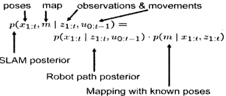
Figure 4.3: Given two maps ml and m2 with similar regions (green shaded) in (A), the search algorithm function transforms map m2 by rotations and translations to find a maximum overlap between ml and ml while map ml remains still in this process (B) [7]
4.3 Notation and problem definition
Definition: Given two maps mx and m2, the goal of a merging process between
the two maps is to find a transformation T so that the two maps can be overlapped. Transformation T is a combination of rotation W followed by a translation along X and Y axis of Ax & Ay respectively.
Transformation T can be represented as 3x3 matrix:
T(Ax,Ay,V) =
cos *¥ - sin ¥ Ax sin1!7 cos^ Ay
0 0 1
We assume that the resulting map of the above transformation is map m'2 hence:
Therefore, the goal of transformation T is to have the maximum similarity between m\ and m, . In other words, map merging is an optimization problem in which it is required to satisfy the following condition:
Maximize Similarity (m,, Tx e (m2 ))
This optimization task has to be performed over a three dimensional space of two translations and one rotation which is similar to the docking problem studied in computational biology (PPI-protein to protein interactions) solved by higher dimensional search [12].
In fact, since there is infinite number of possible transformations, there should be a kind of metric or mechanism to evaluate the quality of the transformations and subsequently pick up those providing the maximum overlap. This issue is what is going to be discussed in the following section.
4.4 How good the Transformation is?
In the previous section, we formulated the problem of map merging between two local maps as an optimization problem aimed to find the maximum similarity between a set of possible transformations of one local map with the other local map. To fulfill our target, an effective heuristic method is necessary in order to pick up and subsequently apply the best transformations with the least costs. In our approach, we will be using an improved version of the basic Adaptive
Random Walk algorithm proposed by Howard [24] for this purpose. Based on our
proposed modified version of adaptive random walk, only a subset of the candidate transformations which meet certain conditions will be considered for the transformation task. The criteria for the selection process are as follows:
• Only those candidate transformations falling in an enclosed area of a Gaussian distribution with mean /^and covariance of E around the point of meeting (the position of the observed robot within the local map) will be considered, c is the point of meeting and constant k = a.gridsbe. The size of the gird cell, gridsize, is an environment dependant variable and a is a constant coefficient determined by the experiment.
In Figure 4.4, a brief illustration of this approach is presented in which, R1 is the robot which was observed by the observing robot (R2) inside R2's local map (local map2). In such a condition, only those candidate transformations for R1's local map (local mapl) which are located within the defined Gaussian distribution will be considered for the transformation evaluation process. Finally, those transformations selected in the previous step will be used in the process of transforming R1's local map to best fit with R2's local map.
Gaussian (U c, v J observed robot (Rl)
l o c a l m a p 2
st<^
Point of meeting ( c ) Observing robot (R2)
IW*»~«.
L o c a l m a p l
Figure 4.4: Only those candidate transformations falling in an enclosed area of a Gaussian distribution with mean „ and covariance of £ around the point of meeting will be
considered. Rl is the robot which was observed by the observing robot (R2) inside R2's local map (local map2). In such a situation, only those candidate transformations for Rl's local map (local mapl) which are located within the defined Gaussian distribution will be considered for the transformation evaluation process in order to transform Rl's local map to best fit with R2's local map
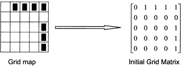
in which an occupied cell is represented by value " 1 " while free cells are represented by values of "0" (see Figure 4.5).
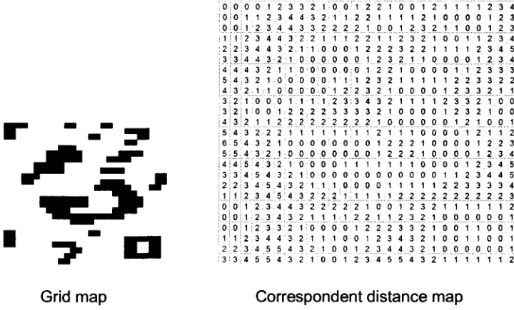
In fact, initial grid matrices are not very efficient representation for the task of pattern lookup required in robot map transformation, since it is very possible that it would generates false positive transformation candidates. A false positive is a chosen transformation believed to be true matching one, while in fact it is false one and would generate a wrong overlap. The high number of false positives using grid matrices is due to the limited number of distinct values (only 0's and 1's) being used in this representation which in turn causes an increases in the possibility of a false random pattern match. Therefore, a more efficient representation for this purpose which maintains the description of the free and occupied cells patterns is necessary. A distance map can be a suitable alternative to provide such representation and also to reduce the computation complexity [7]. In a distance map, a distance computation function calculates the distance using a pattern recognition distance function (i.e. Manhattan, Euclidean or City block) between the free cells and the occupied cells.
In particular, occupied cells get a value of zero (since they have a distance of 0 to the nearest occupied cell which are themselves), while other cells will be assigned a value which is equal to the distance (expressed in the number of cells) to the nearest occupied cell (see Figure 4.6). The general formulation of this approach is as follows:
0 0 0 0 0 1 0 0 0 0 1 0 0 0 0 1 0 0 0 0 1 0 1 1 1
Grid map Initial Grid Matrix Figure 4.5: Simple initial grid represented mop along with its equivalent grid matrix. Each occupied cell (obstacle) is valued at 1 while each free cell is valued at 0 in the related grid matrix.
I
1
0 1 1 1 1
0 0 0 0 0
0 0 0 0 1
0 0 0 0 1
0 0 0 0 1
1 0 0 0 0"
2 1 1 1 1
3 2 2 1 0
4 3 2 1 0
4 3 2 1 0
Grid matrix Distance map Figure 4.6: Initial grid matrix of the previous simple map along with its distance map. In the distance map matrix, each occupied cell will have a value of 0, while free cells will have a value shows the distance (expressed in number of cells) to the nearest occupied cell.
Distance map is an array of Manhattan-distance to the nearest point with value c (c is "1" in our approach) in map m for all positions of px - (x^yj
d - mapc [xx [y, ] = min{m d(p{, p2 )\m\p2 ]=c} (1)
In which, md(px,p2) = |x, -x21 +\yx — y2\ 's the Manhattan-distance between
points p1 and p2- Figure 4.7 shows the initial grid map along with its equivalent
distance map matrix of an area with square shape.
4 3 2 1 1 3 2 1 0 0 2.1:1 0 0
i b 6:6 i"
1 0 0 1 2 2 1 1 2 2
1 1 0 0 3 3 3 3 2 2 1 1 2 2 3 4 4 5 4 3 ..?. T 1 j |2 "j" J T J
2 3 4 4 3 3 4 5 5 4 4 5 5 4 3
1 1 0 0 1 0 0 0 6 o oo 1 1 2 ' 2 ;
1 1, 1:1 oo 1:1 1 2 2 2 3 2 "•j-2 1 •y 1 ...I ?.... 1 1 0 0 0 1 1 1 6 6
1 0 o o: 2 1 1 1 3 2 1 0 2 1 0 0
0 1 0 0 0 1 1 2 2 2 1 2 2 1 1 2 3 4" 3 2 1 0 0 1 2 2 1 1 1 1 0 0 0 0 0 0 1 1 1 1 1 2
l66 l"
2 1 1 2 2 2"" 2"""3 1 2 3 4 2 3 4 4
3 4 5 5
1 1 0 0 1 1 0 0 0 0 1 1 0 1 1 2 1 1 2 2 1 1 2 2 2 3 3 2 3 2 3 2 3 2 4 3
2 3 3 3 3 3 2 2 3 2 1 1 1 0 6 0 0 0 1 2 2 1 1 1 0 0 0
0 6 1
1 0 0 1 1 0 0 0 2 1 1 i
2 1 0 0 2 1 0 0 1 0 0 1 2" 1 1 2 1 2 2 3 1 2 3 4
2 3 4 5 3 4 4 5 3 3 3 4 .?...2 2 . 3 1 1 1 2 0 0 0 1
1 6 6 1
1 0 0 1 0 0 0 1 1 i 1 2
Grid map Correspondent distance map
Once the distance map is constructed, we will be ready to apply the candidate transformations. However, we still need a metric to measure the effectiveness of the transformations.
Definition: Given the distance matrices for maps mx and m2, picture distance
function, y/ is declared as: [7]
y/{mx,m2) = jT d(m],m2,c) + d(m2,mi,c)
where (2)
dim. ,m0,c) = Lii2-n
As it can be noticed from equation (2), the idea of picture distance function is to measure the similarity between the two local maps in a mutual way in order to reduce the number of false overlaps to the lowest proportion possible. Hence, considering maps ma and m2, in the first run, map mx is being kept in a stationary status while m2 is being transformed to maximally overlaps m^ then the distance map for the two maps is being calculated. In the second run, maps m^ and m2
exchange their roles and by keeping m2 in a stationary status, we try to transform
mx to best overlap with m2. In order to get more accurate results, the values obtained from the picture distance function will be divided by the total number of occupied cells to consider the average success ratio as the final measurement criterion. It is clear that the most desired transformations will be those with picture distance values close to zero.
4.5 Failure detection
still be a false positive. Therefore a mechanism is needed to verify the correctness of the proposed transformations. Fortunately by introducing a simple metric called acceptance index (co), it is possible to perform this verification task easily and efficiently.
Definition: acceptance index, CO is the ratio of the number of matching cells
(both O's and both 1's) in the maps being merged to the total number of cells and is defined as follows: [10]
a>(M„M2) =
0 If Ji»i(M„Af2) = 0 (4)
sim(Mx,M2)
sim(Ml,M2) + dsim(Ml,M2) 'f sim(<M^M^ * 0
Therefore, only values close enough to 1 for co, show a real overlap. Since these values are indiscrete, a threshold has to be defined to separate successful from unsuccessful merges. Based on different experiments conducted in the work of [7], it is indicated that values over 0.98 for co shows a reliable threshold in order to confirm the success of the merge attempts, especially considering the fact that the best false positive gives values of CO pretty lower than 0.90. Hence, if the acceptance index satisfies the threshold, the overlap is confirmed and a new (partial) global map is being generated which will be used as the updated belief of the mapping robots (the ones whose partial maps were merged). Otherwise, the overlap is dismissed and the associated transformation will be reversed and the robots resume their own mapping task until next meet.
Algorithmic notation
each other and are able to exchange information, they will try to localize each other in their local maps using a modified version of partial localization and particle filter proposed by Howard [24]. If the mutual localization process was successful (Line 6), the distance map matrix for the local map will be created using equation (1) - explained in the previous section (Line 7). In the next step, a set of candidate transformations will be chosen using equations (2) and (3) -explained in previous section. The validity of these transformations needs to be verified and this duty is being performed using the acceptance index (Line 9). If the selected transformation was acceptable, the merge operation will be confirmed and a new update in the mapping belief of both robots will be adopted (Line 11). In fact, the obtained combined cluster makes up the union of the local maps of both robots right before the moment of the merge operation. On the other hand, if the evaluation process invalidates the associated transformation, it will be reversed (Line 15) and the robots continue their mapping tasks based on their pervious mapping statuses until next meet (Line18)
Algorithm 1 Clustered map merging in Multi-robot SLAM
1: 2: 3: 4: 5: 6: 7: 8: 9: io: 11: 12: 13: 14: 15: 16: 17: 18: 19:
N robots perform SLAM (individually), //initially N single clusters
while 1 do
if any two robots meet and their maps are not merged before then
Each robot takes a relative distance and bearing measurement
Each robot tries to localize the colleague robot in its local map using partial localization [24] if successful localization then
Build the distance map matrices [(1)]
Determine the candidate transformations between the two robots' maps Verify the correctness of the transformation [(4)]
if acceptable then
Build the partial global map and update the beliefs of both robots Robots with merged maps continue mapping within the cluster
end if else
undo the last transformation
end if end if
Robots without merged maps perform SLAM
end while
[(2) and (3)]
Chapter 5
IMPLEMENTATION AND EXPERIMENTAL RESULTS
In order to verify the performance of our proposed method and also to test the efficiency of the algorithm, we have conducted several experiments using Microsoft Robotics Developer Studio simulation environment. In the first section of this chapter we will present the implementation details of our experiments including platform, programming environment and implementation of the code in MRDS simulation environment, while the details of each experiment and its related results will be presented in section 5.2. Section 5.3 consists of a study and analysis on the obtained results.
5.1 Implementation details
5.1.1 Why MRDS?
Microsoft® Robotics Developer Studio is a powerful application package which can be used for the design and implementation of different robotics applications. MRDS supports a wide range of robotics platforms by either running directly on that platform or controlling it from a Windows device by means of a communication channel such as Wi-Fi or Bluetooth®. [46]
be forwarded and watched on the screen which can save the costs and space needed especially during the design and test stages.
5.1.2 Robot
We have decided to use Pioneer 3DX robot (Figure 5.1) for our experiments. Pioneer 3DX (P3DX) from Mobile Robots Inc. is an advanced research machine that can has an on-board PC, a range of sensors and it communicates via WiFi (Wireless Ethernet). The P3DX is supported by Microsoft robotics applications in both hardware and simulation. In fact, Pioneer 3DX is a powerful mobile robot in which an accurate motion model and a precise perception system are encapsulated in one machine.
Moreover, Pioneer 3DX is a multi-purpose robot, used for research and applications involving: mapping, teleportation, localization, monitoring, reconnaissance, vision and other applications [54]. Moreover, Pioneer 3DX runs well on hard surfaces and it can traverse low sills and climb most wheelchair ramps. A summary of operations manual is provided in Appendix A.
Figure 5.1: Pioneer3DX mobile robot is a powerful multi-purpose machine equipped with accurate sensors [53]
Laser range finder in Pioneer 3DX
measure is 0.25°, 0.5° or 1.0° wide. The scan rate is10-12 scans/second with 4 cm range resolution while the maximum range is 50-80 meters [53]. The accuracy of the LRF will drop sharply with the existence of mirrors, glass, and matte black obstacles. In such a case, a complementary sensor, like sonar will be necessary to amend the inaccuracy of the LRF sensor. A typical laser scanner output will look like the following:
2.98, 2.99, 3.00, 3.01, 3.00, 3.49, 3.50, ..., 2.20, 8.17, 2.21
The above numbers show the range readings from right to left in terms of meters.
5.1.3 Mapping environment
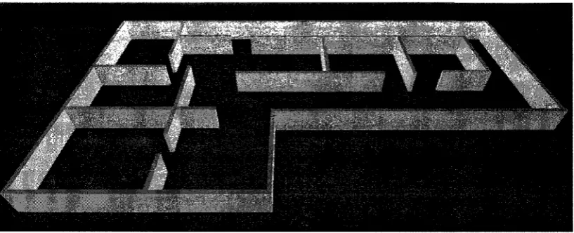
We have used two different environments for the experiment stage. The first experimental environment is an area enclosed in a rectangular shape with dimensions of 24m x 18m (Areal). The second environment (Area2) resembles an L-shape area with dimensions of 36m x 27m. The difference between the two areas goes back to the shape and position of the walls and other obstacles.
Areal includes a set of unorganized walls which will be used in our later
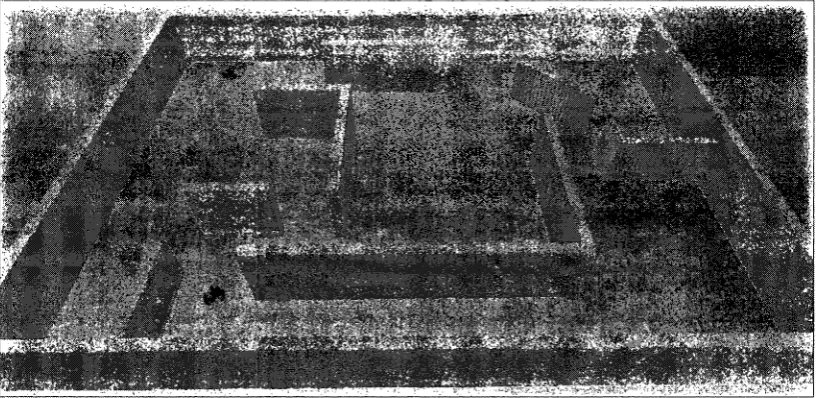
performance evaluation of the proposed method representing an asymmetric environment (see Figure 5.2). On the other hand, Area2 is an ordinary office space with several rooms and corridors with regular partitioning walls and entrance doors. The non-similar corners of the mapping area and the partitioning walls are aimed to provide a better and more realistic measurements as well as preventing the scenario from falling into symmetrical environment exploration ambiguities, (see Figure 5.3)
the expense o
LRFs are o accurate to 2cnm or 4cm, so grids smaller than this do not improve
uence they range from 0 to 255. However, there are jccupied/vacant cells since it is not necessary for the probabili 3>r 0 respectively. Therefore the range is arbitrarily dividec
= 65 = 191
This conforms to the convention that is commonly used for occupan' the literature where: Black (Occupied) represents obstacles, Grey
own, and White (Free) is free (clear or empty) space.
gnc
•ISt. %
<&t\»ffc.J!
'*'•'*". *£&••• WU'Wh $
iHlSifll: ^ )• '$M
Figure 5.3: Area2, the second experimental mopping environment, a regular indoor office area with different sized rooms and corridors.
5.1.4 Programming platform
The implementation of the experiments was done using .net technology in Microsoft Visual Studio and the programming language is C#. As mentioned before, it is very convenient to direct the output of projects created in MVS development environment to MRDS simulation environment using manifest facility. A manifest is a special platform aimed to build the structure and shape of the output (simulation environment) and holds the required directions and configurations necessary to construct the required simulation environment. In fact it acts as a configuration file for the MRDS simulation environment.
The single robot SLAM method used in our implementation is based on Simple Mapping Utilities (pmap) SLAM implementation by A. Howard [24]. The original code was in C++ and it has been rewritten in C# to be used in our implementation. The multi-robot extension is based on the idea of grid similarities and picture distance functions proposed by [7] and [12]. Also we have used the IR sensor for the purpose of distance estimation between the mapping robots.
5.2 Simulation experiments
mapping tasks from two different locations (the first one starts from the middle point while the second starts from the left part of the area). Each mapping experiment includes a three sub-experiments which are, sole mapping, co-operative dual robots mapping without our proposed enhancement and finally dual robot mapping with the in advance pairwise partial localization enhancement. The simulation experiments were performed on a laptop computer with 4GB of RAM and a Dual-core T4200 Pentium CPU @ 2 GHz.
5.2.1 Gaussian pdf parameters
As mentioned earlier, the essence of our approach is to consider and apply only an effective subset of the candidate transformations at each data exchange instance between the two robots. Our filtering mechanism is a Gaussian pdf which reduces the cloud of the possible transformations to those falling in an enclosed Gaussian distribution area around the point of meeting. The related Gaussian pdf has a mean of /icand covariance of X* 'n which, c is the point of
meeting and k = a.gridsize is a constant coefficient which is dependant to the grid cell size and also the mapping environment shape. Hence k, is the first value that needs to be determined by our experiments.
Since the grid size is 0.05 meters (5 centimeters) and the robot diameter is 0.5 m, then the maximum proper value for k will be 0.5 m. in other words the upper-bound for a will be 10. Therefore we will examine the performance of our method for the integer values of OC ranging in the interval of 1 < a < 10. In fact when OC • 0, the set of candidate transformations • O (empty set) and hence, the number of data exchange operations • 0 too and practically the multi-robot mapping task becomes a single robot mapping task in which the other robot becomes an obstacle to be prevented.
To evaluate the influence of OC on the mapping process, we define the following metrics:
(1)
Number of successful transformations
(2)
Transformation Ratio = Number of successful transformations Total number of successful transfor mations for all values
(3)
Weighted Throughput = Transformation Effectiveness * Transformation Ratio
In equation (1), we consider the ratio of successful transformations to the total number of transformations performed in a mapping task. This metric is a suitable criterion to measure the performance of the mapping methods. On the other hand, equation (2) calculates the Transformation ratio for a multi-fold mapping experiments set and finds the weight (significance) of each fold. Finally, in equation (3) we calculate the weighted throughput for each mapping task trial.
In order to find the best value of Oi for our mapping method implementation, we have conducted three experiments for each value of a ranging from 1 to 10 to find the related average weighted throughput. These experiments were performed based on our proposed multi-robot mapping method in Area2 using two mapping robots. The results obtained from these experiments are shown in Table 5.1. We can observe from these results that the best average weighted throughput of 0.176 was achieved by <2= 7. This result means that 17.6% of the
^^^MS^^B « = i
« = 2
« = 3
« = 4
Of =5 a =6 OC"7 a =8 a =9 or =10 SKfifS^ 0.007 0.039 0.042 0.101 0.132 0.149 0.158 0.162 0.121 0.082
Bill
0.011 0.043 0.048 0.092 0.149 0.148 0.187 0.169 0.108 0.081 d Throughput Third Average 0.009 0.031 0.052 0.084 0.118 0.162 0.184 0.155 0.109 0.068 Total 0.009 0.038 0.047 0.092 0.133 0.153 0.176 0.162 0.113 0.077 1.000Table 5.1: average weighted throughput for each value of Ot ranging from 1 to 10. On CC = 7 we obtained the best weighted
successful transformations made by all values of 1 < a < 10 were made in the fold of cc= 7. A graph representing the relationship between the values of cxarid the weighted throughput is provided in Figure 5.4.
Average Weighted Throughput 0.2
0.15
0.1
0.05
0
1 2 3 4 5 6 7 8 9 10
Figure 5.4: Average Throughput for different values of a
Discussion:
To analyze the trend of the above graph, it has to be mentioned that initially when oc has the value of 1, the Gaussian pdf would have very small values around the mean (the point of meeting coordinates) and hence, many candidate transformations (both successful and unsuccessful) will be dismissed as they lay outside of the consideration region. In other words the multi-robot method will have a behavior similar to single robot mapping method. As the value of orgrows the radius of the consideration region extends too and covers a wider set of candidate transformations. In some points of this range, our algorithm will show its best performance. On the other hand, when a. continues in taking higher values, the region of consideration becomes huge and our algorithm starts to lose its efficiency since the number of false positive transformations inside the region of consideration will increase rapidly and our method will behave similar to the Basic multi-robot mapping approach.
5.2.2 Mapping experiments
5.2.2.1 Areal Mapping experiments
In the first set of these experiments, Robotl and Robot2 start to map Areal individually. At each run the other robot has been eliminated to prevent the mapping robot from dealing with an unintended obstacle. Our target was to have 10 successful experiments with complete coverage of the mapping area. To accomplish this aim, we had to repeat the mapping experiment 14 times. The other 4 unsuccessful experiments failed to completely cover the mapping area after 120 minutes (two hours) because the mapping robot was stuck in some parts of the map. Results for mapping time using single robot (Robotl and
Robot2) are reflected in Table 5.2. Since we assume that the initial pose of the
mapping robot is unknown, we treat the results obtained for both robots equally in computing the average time needed to map Areal, and therefore this average will be considered in the analysis and study stage.
Run 1 2 3 4 S 6 7 8 9 10 Average Robotl 19.18 14.54 18.00 14.38 15.59 12.35 17.02 11.85 13.40 15.55 15.19 Robot2 18.38 14.46 17.59 12.80 19.27 14.85 21.20 16.53 15.20 18.76 16.90 Average 18.78 14.5 17.8 13.59 17.43 13.6 19.11 14.19 14.3 17.16 K B Table 5.2: Robotl and
Areal mapping time for single Robot2 individually

![Figure 4.3: Given two maps ml and m2 with similar regions (green shaded) in (A), the search algorithm function transforms map m2 by rotations and translations to find a maximum overlap between ml and ml while map ml remains still in this process (B) [7]](https://thumb-us.123doks.com/thumbv2/123dok_us/1455867.1178386/39.597.228.412.181.345/figure-algorithm-function-transforms-rotations-translations-maximum-overlap.webp)