ISSN(Online): 2320-9801
ISSN (Print) : 2320-9798
I
nternational
J
ournal of
I
nnovative
R
esearch in
C
omputer
and
C
ommunication
E
ngineering
(An ISO 3297: 2007 Certified Organization)
Vol. 4, Issue 3, March 2016
Design, Simulation and Implementation of
Microstrip Meander Line Antenna for an
Integrated Transceiver System
Prof. Prakash S. Andhare,
Research Scholar (Communication Engineering), Dept. of E & C Engineering, MIT, Aurangabad, Maharashtra, India
ABSTRACT: This paper focuses on the design, simulation and evaluation of the meander-line antenna geometry. One
standard meander-line antenna and other one non-standard meander antennas have been studied. These printed antennas are discussed with the goal of identifying which is suitable for use in a miniaturized wireless transceiver design and which is able to provide the better performance using minimal Printed Circuit Board (PCB) space. In a word, the main objective is to characterize tradeoffs and identify which antenna provides the best compromise among volume, bandwidth and efficiency.
Ansoft High Frequency Structure Simulator (HFSS) is used to simulate expected characteristics which are resonant frequency, bandwidth, VSWR, and radiation pattern. HFSS is used to provide a good guide for the antenna design before the actual prototype is manufactured. Simulated results are compared with results of measurement to point out the differences and help demonstrate the practical effects on antenna performance. Radiation pattern are measured to illustrate the effects of antenna miniaturization. All the above measurements are done in the anechoic chamber. The performance of each antenna is evaluated based on return loss, operational bandwidth, and radiation pattern characteristics. During our measurement, return loss is measured by reading the S11-port reflection coefficient on Vector Network Analyzer (VNA). This coefficient can be used to characterize how well the antenna is able to be efficiently fed. Operational bandwidth is measured as the frequency range over which the antenna keeps the value of Voltage Standing Wave Ratio (VSWR) or equivalently has -10dB return loss.
KEYWORDS: Meander Line Antenna, RFID, GCPW, HFSS, BALUN, PCB, Vector Network Analyser.
I. INTRODUCTION
It is indisputable that antenna plays a significant part in communication system. Therefore, an increasingly number of technicians begin to do some research and development of antenna. However, with rapid development of the communication industry, the requirement of antenna will be achieved with high quality. Nowadays, there are different kinds of antennas in the market such as dipole antenna, patch antenna, loop antenna, meander-line antenna and so on. In order to meet the demand of developing communication equipment the research of antennas focuses on some particular aspect, for instance, how to reduce the size of antennas while maintaining higher radiation efficiency. Meanwhile, with the improvement of Small Scale Integrated circuits, the size of communications equipment is also getting smaller and smaller. Clearly compared with communication equipment, the dimension of antenna is too large. Therefore, the reduction of antenna size will be our research topic. In our thesis, we are trying to find a good antenna design solution on the reduction of the antenna size while maintaining higher efficiency.
The coupling element and meander line antenna affect size of antenna and radiation efficiency in antenna structure, it has been introduced in background [1][3]. Thus coupling element and mender liner antenna will be studied.
The primary goal of this project is to design an antenna which operates at 433MHz with higher radiation efficiency and smaller size for the use in an integrated transceiver design. The entire design, including CC1101, balun, matching
circuit and antenna, must fit on a single sided FR4 PCB (εr=4.4).All circuitry components including the transceiver
chip, reference crystal and matching network must fit into the predefined ground plane area with dimensions of 40 mm length, 30 mm width and 1.2 mm thickness.
ISSN(Online): 2320-9801
ISSN (Print) : 2320-9798
I
nternational
J
ournal of
I
nnovative
R
esearch in
C
omputer
and
C
ommunication
E
ngineering
(An ISO 3297: 2007 Certified Organization)
Vol. 4, Issue 3, March 2016
measurement of input-port reflection coefficient, efficiency and bandwidth. Specialized equipment and an anechoic chamber will be used to measure antenna radiation patterns and characterize the antenna sensitivity to horizontally and vertically polarized data. The benefits and drawbacks will be shown in the last chapter and it will be demonstrated that there is no ideal antenna for each situation.
II. RELATED WORK
Radio Frequency Identification (RFID) of objects or people have become very popular in many services industry, distribution logistics, manufacturing companies and goods flow systems [1]. In all these applications data are transferred to a local querying system from a remote transponder including an antenna and a microchip transmitter, a suitable antenna for this remote transponder must have low-profile, low-cost and small-size and the bandwidth requirement is less important [1].
It is well known that the printed antenna is very mature in certain frequency such as GSM-900MHz DCS-1800MHZ and ISM-2400MHz. Printed antenna includes many advantages and attractiveness. It is easy to fabricate, low-cost and small-volume, In order to work on Small Scale Integrated circuit board, designing a small size antenna is necessary. The microstrip patch antenna is not suited. Base on G.A. Mavridis research, the miniaturized meander microstrip patch antenna was designed. The dimension of antenna with 36*44*0.75mm and antenna operating at 435MHz is designed
on the Rogers RO3003 laminate substrate with εr=3.One study shows that the current on the surface of the patch is
forced to follow a mender route [2]. Thus we increase the electrical length and the antenna’s electrical size decreases. However, it does not improve the radiation efficiency of antenna because of low profile. The research solved the problem of the size of antenna, but it didn’t take too much consideration of the radiation efficiency of antenna. S.VILLERS investigates how to reduce size of patch antenna for 400MHz. The research applied techniques of reduction of dimensions [4], by achieving slots to the non-radiating edges and by introducing short-circuit points between the patch and the mass. In this way the total size of antenna is 91*66mm and the research reduces the dimensions of a factor 3, [5] but it is not enough. Next, we consider the planar folded dipole antenna. This kind of
antenna requires about 0.5 λ length generally for obtaining a good performance [6]. Therefore, the size of folded dipole antenna is larger than the microstrip meander antenna because of monopole antenna has a mirror ground [7].
In our case, for the purpose of reducing the size of transponder, a meander-line antenna (MLA) is an attractive choice. As proposed in [8] and discussed in [9], this class of antennas provides the largest size reduction at a given frequency at the expense of a narrow bandwidth. Compared with the PIFA antenna, there is an advantage that the MLA is relatively easy to catch larger relative bandwidth. Also, according to [10] Meander-line antenna is a truly transformation of Monopole antenna. Therefore, in our work, we make a study on the meander-line antenna.
III. PROPERTIES OF MEANDER LINE ANTENNA
The meander line antenna is a type of microstrip antenna that achieves miniaturization in size by embedding the wire structure on a dielectric substrate. Antenna integration and miniaturization are two major challenges. In basic form meander line antenna is a combination of conventional wire and planer strip line. Benefits include configuration simplicity, easy integration to a wireless device, inexpensive and potential for low SAR features. Meander line antenna is one type of the micro strip antennas. The meander line antenna was proposed by Rashed and Tai for reduce the resonant length.
3.1 Principle of Meander Line Antenna
Meander antenna is electrically small antenna .The design of meander line antenna is a set of horizontal and vertical lines. Combination of horizontal and vertical lines forms turns. Number of turns increases efficiency increases. In case of meander line if meander spacing is increase resonant frequency decreases. At the same meander separation increase resonant frequency decreases. The meander line element consists of vertical and horizontal line so it formed a series of sets of right angled bends. The polarization of antenna depends on radiations from the bend. The spacing between two bends is very vital, where if the bends are too close to each other, then cross coupling will be more, which affects the polarization purity of the resultant radiation pattern.
ISSN(Online): 2320-9801
ISSN (Print) : 2320-9798
I
nternational
J
ournal of
I
nnovative
R
esearch in
C
omputer
and
C
ommunication
E
ngineering
(An ISO 3297: 2007 Certified Organization)
Vol. 4, Issue 3, March 2016
the figure will affect the antenna performance parameter [10]. In order to find the best antenna solution, different values of meander width are simulated and studied. Radiation efficiency of meander line antenna is good as compare to
conventional half and quarter wavelength antennas. Antenna size reduction factor β depends primarily on the number
of meander elements per wavelength and spacing of element widths of the rectangular loops. Planar meander line antenna with added quarter wave parasitic element at the both side of the meander can produce double beam radiation pattern at frequencies much lower than resonances of a single-element antenna of equal length.
A meander-line antenna can be realized by bending the conventional linear monopole antenna to decrease the size of antenna [11]. The influence of the meander part of the antenna is similar to a load and the meander line sections are considered as shorted-terminated transmission lines as shown in Figure 3.2.
Fig. 3.1 Shape of Meander Line Antenna (MLA) Fig. 3.2: Equivalent Model of meander line sections [11]
The meander line section can be modelled as an equivalent inductor. In the far-field pattern, in the result of the cancellation of magnetically fields, the transmission lines of a meander line antenna do not radiate fields. The radiation fields will be radiated from the vertical pars of MLA. The currents’ intension of vertical parts can be clearly seen in Figure 3.3. The meander line antenna acts as a resonant LC circuit. The vertical elements act as the inductor, horizontal elements act as capacitor. The horizontal lines lie in the short length of the PCB while the vertical lines are placed along the long length of the PCB. The meander line configuration of the monopole allows reducing the occupied space of the antenna element to less than 0.1λ0 in each dimension.
Fig. 3.3: Electric Current Magnitude Plot for the MLA. [11]
ISSN(Online): 2320-9801
ISSN (Print) : 2320-9798
I
nternational
J
ournal of
I
nnovative
R
esearch in
C
omputer
and
C
ommunication
E
ngineering
(An ISO 3297: 2007 Certified Organization)
Vol. 4, Issue 3, March 2016
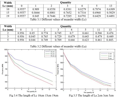
3.1, and table 3.2 compared with figure 3.4 and 3.5. It is clearly known that when the length of width (Lc) and width (La) are larger, the resonant frequency will reduce quickly, and the shifted frequency is not linear.
Width Lc (mm)
Quantity
0 1 2 3 4 5 13
10 0.9557 0.909 0.8558 0.8381 0.8279 0.7874 0.6309
15 0.9557 0.8666 0.8001 0.7652 0.7316 0.6968 0.5029
19 0.9557 0.845 0.7646 0.7285 0.6791 0.6429 0.4491
Table 3.1 Different values of meander width (Lc)
Width La (mm)
Quantity
0 1 2 3 4 5 11 13
2 0.956 0.85 0.774 0.745 0.7 0.661 0.506 0.476
3 0.956 0.845 0.765 0.729 0.679 0.643 0.479 0.449
5 0.956 0.844 0.749 0.709 0.666 0.623 0.461 0.445-
Table 3.2 Different values of meander width (La)
Fig 3.4 The length of Lc 10cm 15cm 19cm Fig 3.5 The length of La 2cm 3cm 5cm
We make two antenna designs. For different designs, they have different values for H and Lc. The First Antenna Design: H =13 mm, Lc = 38 mm, La = 3 mm, Lb = 7 mm. 9
The Second Antenna Design: H = 5.5 mm, Lc = 36 mm, La = 3 mm, Lb = 7 mm.
3.2 Integrated Transceiver CC1101
ISSN(Online): 2320-9801
ISSN (Print) : 2320-9798
I
nternational
J
ournal of
I
nnovative
R
esearch in
C
omputer
and
C
ommunication
E
ngineering
(An ISO 3297: 2007 Certified Organization)
Vol. 4, Issue 3, March 2016
Figure 3.6: Top View of the Pin out [11].
IV.MODELING OF MEANDER LINE ANTENNA AND SIMULATION RESULTS
4.1 The first Meander-line Antenna Design and Simulation
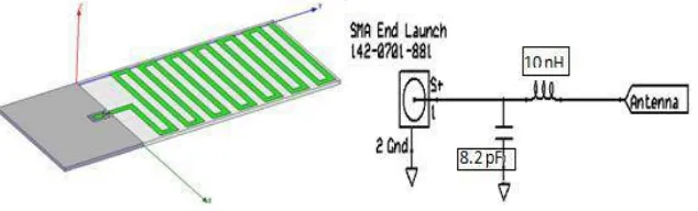
The first small size of meander-line antenna is designed. The meander-line antenna with dimension of
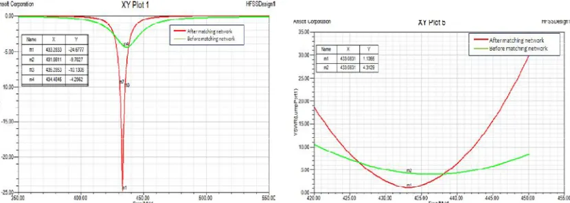
105mm*39mm*1.2mm, the substrate dielectric constant εr=4.4. Based on HFSS simulation it is shown that the S11 return loss is -6 dB at 433 MHz before addition of the matching network. After adding a series of 10 nH and a shunt of 8.2 pF, the return loss at 433 MHz can be lowered to -20 dB, the radiation efficiency of antenna is 92% and the VSWR bandwidth is almost 8 MHz. The expected peak gain is 0.95 dBi.
Clearly the radiation efficiency of the first meander-line antenna is achieved with demands, but the dimensions of antenna are far from satisfactory. Generally speaking, in order to improve the radiation efficiency of antenna, the total length of the antenna must increase which is the main reason why we have large dimension. For the improvement of the antenna size, in the next part the second meander line antenna is designed.
Figure 4.1: The first MLA orientation and simulated matching network required for 50-Ohm match.
ISSN(Online): 2320-9801
ISSN (Print) : 2320-9798
I
nternational
J
ournal of
I
nnovative
R
esearch in
C
omputer
and
C
ommunication
E
ngineering
(An ISO 3297: 2007 Certified Organization)
Vol. 4, Issue 3, March 2016
Fig. 4.4 (a): The first MLA 3D-RP expressed as Gain in dB (b): The first MLA 2D- RP expressed as Gain in Db
4.2 The second Meander-line Antenna Design and Simulation
According to the second meander-line simulation, the dimension of the antenna is 75mm*39mm*1.2mm, the return loss is -4 dB which is not good. After addition of matching network (a series of 2.4 nH and a shunt of 11 pF), the return loss is -25 dB at 433MHz. The radiation efficiency of antenna is 39%The VSWR bandwidth is 5 MHz the expected peak gain is -4 dBi. Obviously, increasing radiation part and decreasing electric length are used to improve the size of the antenna. The size of the antenna is quite satisfied with our requirement, but unfortunately, the efficiency of the antenna, the gain of the antenna and bandwidth is lower than the first meander line antenna. Just as chapter 1 mention that the size will affect efficiency, gain and bandwidth.
Fig. 4.5: The second MLA orientation and simulated matching network required for 50-Ohm match.
ISSN(Online): 2320-9801
ISSN (Print) : 2320-9798
I
nternational
J
ournal of
I
nnovative
R
esearch in
C
omputer
and
C
ommunication
E
ngineering
(An ISO 3297: 2007 Certified Organization)
Vol. 4, Issue 3, March 2016
Fig. 4.8 (a): The second MLA 3D-RP expressed as Gain in dB (b): The second MLA 2D- RP expressed as Gain in dB
V. ANTENNA MODEL AND MEASUREMENT RESULTS
5.1 Antenna Model
In this section, all the PCB designs will have their layouts using PADS 9.0 software. Figure 5.1 shows the completed drawings of our antennas. Figure 5.2 shows the final designs of our antenna models.
Fig. 5.1: Completed Antenna Drafting Using PADS 9.0. Fig. 5.2: Completed Antenna Models.
5.2 MEASUREMENT RESULTS
In this chapter, we do the S11 measurement after addition of our matching network. In the case of the real measurement, there are few differences between actual values of matching network and the simulated values. Return loss (S11), Smith Chart and VSWR after addition of matching network are measured using Network Analyzer.
5.2.1 The First Meander-Line Antenna
ISSN(Online): 2320-9801
ISSN (Print) : 2320-9798
I
nternational
J
ournal of
I
nnovative
R
esearch in
C
omputer
and
C
ommunication
E
ngineering
(An ISO 3297: 2007 Certified Organization)
Vol. 4, Issue 3, March 2016
Fig. 5.5: E-plane Co-cross polarization (R: Co-polarizan) Fig. 5.6: H-plane Co-cross polarization (G: Cross-polarizan)
5.2 The Second Meander-line Antenna
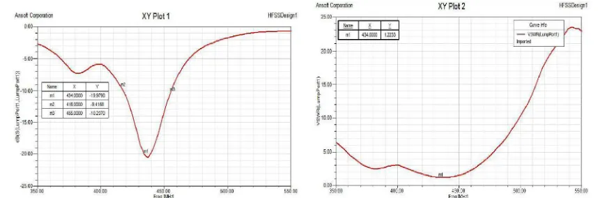
Fig. 5.7: The second MLA RL (S11) expressed in dB after matching. Fig. 5.8: The second MLA VSWR after matching
VI.CONCLUSION AND FUTURE WORK
In this project the two-sided printing meander-line antenna and an integrated transceiver circuit are presented. At the beginning of this project, we introduce the development of antenna and it confront with some problems. According to the previous work, the printed antenna is either high efficiency or small size which is introduced in background part .In the objective part introduces the primary goal of this project is to improve the dimension of antenna and the radiation efficiency according to the research meander line antenna model and coupling element technology can solve some problems. We introduce antenna basic theory meander line antenna principle of work and characteristic of coupling element, studying and analysis what is the relationship between size efficiency and antenna gain.
The actual measurement data is better than the simulation. There are many reasons which make the measurement data different from predicted with the simulation. The reason is the board thickness and copper thickness; they are lower thickness than simulation when the board is manufacture. And the main reason is that the ground will affect the antenna S parameters. As we know that the wave resonates only between the antenna and the ground of microstrip. There are some specific reasons which limit this research such as fixed substrate material and the fixed thickness of board. In the future work, different PCB substrate material and thin board can be performance to reduce the size of antenna, also power amplifier can be considered to add in the integrated circuit part to improve the transmission performance.
REFERENCES
1. Gaetano Marrocco, Alessandro Fonte and Fernando Bardati, “Evolutionary Design of Miniaturized Meander-Line Antennas for RFID
ISSN(Online): 2320-9801
ISSN (Print) : 2320-9798
I
nternational
J
ournal of
I
nnovative
R
esearch in
C
omputer
and
C
ommunication
E
ngineering
(An ISO 3297: 2007 Certified Organization)
Vol. 4, Issue 3, March 2016
2. G.A.Mavridis, D.E.Anagnostou, C.G.Christodoulou, and M.T.Chryssomallis “Quality factor Q of a miniaturized meander microstrip
patch antenna”, IEEE Trans. Antennas Propagat, pp.1-4, July 2008.
3. S.Reed, L.Desclos, C.Terrt, S.Toutain, “Size reduction of a patch antenna by means of inductive loads”, Microwave and Optical
Technology Letters, Wiley Periodicals, Inc. Vol 29, pp.79 – 81, 27th Feb 2001.
4. L.Desclos, Y.Mahe, S.Reed, G.Poilasne, S.Toutain, “Patch Antenna size reduction by combining inductive loading and short-points”,
Microwave and Optical Technology Letters, Wiley Periodicals Inc, Vol.30, pp.385 – 386, 15th Aug 2001.
5. J.Rashed, C. Tai, “A new class of resonant antennas”, IEEE Trans. Antennas Propagat., Vol.39, N.9, pp.1428-1430, 1991.
6. G.Leon, R.R. Boix, F. Medina, ”A comparison among different reduced-size resonant microstrip patch”, Microwave and Optical Tech.
Letters, Vol.29, No.3, pp.143-146, 2001.
7. Vincent F. Fusco, “Foundations of Antenna Theory and Techniques”, Malaysia, Pearson Education Limited, 2005.
8. J.R. James, P.S. Hall, ”Handbook of Microstrip Antennas”, London, Peter Peregrinus Ltd, Vol. 1, 1989.
9. Louis E. Frenzel, Louis E, “Printed-Circuit-Board Antennas”, Frenzel, pp.1-2, March 31, 2005
10. Chen, Zhi Ning. “Antennas for Portable Devices”, Sussex, England: John Wiley and Sons Ltd., 2007.pp. 20-21.
11. C.A.Balanis. “Antenna Theory Analysis and Design” New York: John Wiley&Sons Ltd., 1997.pp.1, 28, 723.
BIOGRAPHY
Prakash S. Andhare is a former I/c HOD in the Electronics & Telecommunication Department, at K.T. Patil COE&T,
![Fig. 3.3: Electric Current Magnitude Plot for the MLA. [11]](https://thumb-us.123doks.com/thumbv2/123dok_us/1457102.1178534/3.595.160.439.564.738/fig-electric-current-magnitude-plot-mla.webp)