IJEDR1502153
International Journal of Engineering Development and Research (www.ijedr.org)866
Elimination of Sag Using PV Based DVR Fed by an
Interleaved Boost Converter with Energy
Conservation Capability
Mr.B.Karthikeyan1,Mr.P.Gowrishankar2 1
PG Scolar,2Assistant Professor,
Department of Electrical and Electronics engineering , Maharaja Institute of technology, Coimbatore, Tamilnadu, India
________________________________________________________________________________________________________
Abstract - Power quality is one of major concerns in the present era. It has become important, especially, with the introduction of sophisticated devices, whose performance is very sensitive to the quality of power supply. Power quality problem is an occurrence manifested as a nonstandard voltage, current or frequency that results in a failure of end use equipments. One of the major problems dealt here is the voltage sag. To solve this problem, custom power devices are used. One of those devices is the Dynamic Voltage Restorer (DVR), which is the most efficient and effective modern custom power device used in power distribution networks. Its appeal includes lower cost, smaller size, and its fast dynamic response to the disturbance. This paper introduces power quality problems and overview of Dynamic Voltage Restorer so that young electrical engineers come to know about such a modern custom power device for power quality improvement in future era. Key words: power quality, voltage sags, Dynamic Voltage Restorer (DVR).
________________________________________________________________________________________________________
I. INTRODUCTION
Power Quality
Power quality determines the fitness of electric power to consumer devices. Synchronization of the voltage frequency and phase allows electrical systems to function in their intended manner without significant loss of performance or life.
Power Quality Disturbances
Swells: Momentarily short duration (0.5-30 cycles) increased of the rated voltage (1.1-1.8pu) Transients: High amplitude, short duration (<0.5 cycle) voltage disturbances.
Voltage unbalance: variation of magnitude and/or phase angle from different phase.
Harmonics: voltage and/or current deviation from a true sin wave due to unwanted frequencies that are multiples of fundamental waves.
Frequency deviation: a variation of frequency from 50Hz (e.g. caused by the starting of heavy loads on weaker generator systems).
Flicker: refer to repetitive sags or swells.
Spikes: in phase impulses which increased the instantaneous voltage.
Voltage deviation: a long term charge above (over-voltage) or below (under-voltage) the prescribed normal voltage range. Blackout: refer to a total loss of input voltage for a few cycles or more.
Voltage Sag
A voltage sag (in American) or voltage dip (in British) is a short duration reduction in RMS Voltag which can be caused by a short circuit, overload or starting of electric motor. A voltage sag happens when the rms voltage decreases between 10 and 90 percent of nominal voltage for one-half cycle to one minute. Some references defines the duration of a sag for a period of 0.5 cycle to a few seconds and longer duration of low voltage would be called a "sustained sag".
The term "sag" should not be confused with brownout which is the reduction of voltage for minutes or hours or transient which is the reduction of voltage for a very short duration (less than a half cycle).
IJEDR1502153
International Journal of Engineering Development and Research (www.ijedr.org)867
II.RELATEDWORK
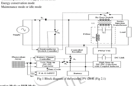
In this work a coordinating logic is used to operate the PV solar system as DVR, utilizing the rated inverter capacity during night time and inverter capacity remaining after excess or equal real power generation on the PV system. This allows utilization of expensive asset of the PV system over 8 h period. The proposed DVR, if connected at the terminals of a home or small industry can conserve 12.6 kW h in sunny days. It reduces the potential panel tariff around $900 per year by reducing the energy consumption from the utility grid . This has additional financial benefit over the conventional DVRs used in the past. It also eliminates the need of UPS and stabilizers for the individual equipment. In order to attain the optimal utilization of PV system, a simple DC–DC Boost converter associated with a function called MPPT is introduced between the PV array and battery. A simulation results and experimental results are presented to validate the existing method The block diagram of the existing PV-DVR is shown in Fig.The proposed system consists of a PV array, low step-up DC–DC converter with P&O MPPT algorithm, battery, high step-up DC–DC converter, PWM inverter, series injection transformer and semiconductor switches S1, S2, S3, R1 and R2.When the grid voltage is normal, switches S1 and S3 are normally closed and S2 is normally open. When the grid fails or when the PV array generates excess power, then the switches are activated and the inverter supplies the load. Tables show the control signals of the semiconductor switches S1, S2, S3 and R1, R2 respectively. The power semiconductor switches are controlled by the voltage sensor and logical components.
The PV-DVR is operated in the following four modes of operation
Compensation mode or DVR mode
Uninterruptable Power Supply (UPS) mode
Energy conservation mode
Maintenance mode or idle mode
Fig 1 Block diagram of the existing PV-DVR (Fig 2.1)
Compensation Mode or DVR Mode
In this mode, the proposed PV-DVR is utilized to regulate the voltage at the load side.During this operation a series injection transformer is configured in series with the load to compensate the voltage sag/swell. The control logic of the DVR mode is shown in table.
Uninterruptable Power Supply (UPS) Mode
In this mode, theseries injection transformer of PV-DVR is reconfigured into parallel to provide the uninterruptable power supply to load on both daytime and night time.
Compensation mode or DVR mode (Table 2.1) Energy Conservation Mode
IJEDR1502153
International Journal of Engineering Development and Research (www.ijedr.org)868
output of the controlled rectifier in parallel with the output of low step-up DC–DC converter to feed the required power to the batteries and load. The control logic of this mode is presented in Table.
Energy conservation mode (Table 2.2)
Maintenance Mode Or Idle Mode
In this mode, the entire PVDVR is disconnected through the semiconductor switch S3 by passing the secondary of an injecting transformer when the DVR needs maintenance.
Fig 2 PV Modeling equipped with Boost Converter (Fig 2.2)
Advantages
Eliminate UPS and stabilizers
Reduces the energy consumption from grid.
Effective in eliminating sag while compared with static voltage regulator and other techniques
Disadvantages
Open DVR phase control loop.
The output current of the boost converter is a pulsed waveform. Thus, a large output capacitor is required to reduce the ripple
The large output capacitor used in boost converter makes PWM dimming more challenging. Turning the boost converter on and off to achieve PWM dimming means the capacitor will have to be charged and discharged every PWM dimming cycle.
III.PROPOSED
In this project, DVR is fed by an interleaved boost converter instead of normal boost converter inorder to efficient sag elimination the same is narrated along with construction the operation.
IJEDR1502153
International Journal of Engineering Development and Research (www.ijedr.org)869
Block Diagram of Proposed work (Fig 3.1)
Simulink structure of the proposed work (Fig 3.2)
The Basic structure is divided into four main parts ,They are
PV / UPS Section
SAG Creation
DVR Section
Heavy Load
PV / UPS SECTION
This section is divided into PV part and UPS when the PV generated power is equals to load requirement the same is fed through the load via DVR hence the same meet the requirement of normal 1:1 load condition and it can be done only during the day time since the PV panel can be operated in presence of sunlight.
IJEDR1502153
International Journal of Engineering Development and Research (www.ijedr.org)870
Control Circuit of Sub system (Fig 3.3)The above fig shows the control circuit for controlling the voltage from the PV which can be directed directly to load and when the PV power is greater than the required load power the control circuit directs the excess power to charge the battery unit. When the PV power is less than load power the battery gets recharges and supports the grid and when the power from PV panel is Zero during night the unit is supported only via grid the charged The below wave form in the fig shows the controlled output current and voltages of scope 1 and 2.
Controlled Output Voltage (Fig 3.4)
Controlled Output Current (Fig 3.5)
SAG CREATION
IJEDR1502153
International Journal of Engineering Development and Research (www.ijedr.org)871
Generation of SAG (Fig 3.6)
Proportion between Source and SAG voltage (Fig 3.7)
DVRSECTION
The below shows the Simulink schematic blocks of the DVR Section which forms the main part of the Proposed work. The Voltage from PV / UPS section is fed into the DVR section via sub system to the DC link i.e.,. the IBC operations are controlled by the PWM.
Simulink structure of the DVR (Fig 3.8)
In this the DVR which injects the voltage to eliminate the sag an interleaved boost converter is equipped to overcome the disadvantages of boost converter ,The DVR is fed with PWM generator via control loop which filters the i/p to IBC and also it separates real and imaginary power using parks equation.
IJEDR1502153
International Journal of Engineering Development and Research (www.ijedr.org)872
Control Loop for parks transformation with filters (Fig 3.9)Filter voltage in control loop (Fig 3.10)
Parks Transformation (Fig 3.11)
To Separate the V real and V Img ,Parks transformation is used as below.
Vd = Sin (ωt) – Cos (ωt) V real Vq Cos (ωt) Sin (ωt) V Img
IJEDR1502153
International Journal of Engineering Development and Research (www.ijedr.org)873
Injected voltage from DVR (Fig 3.12)
The above fig shows the Voltage output from DVR at the exact time period inline with produced sag ,The injusted voltage is fed into the load at the particular time and the sag is migrated or eliminated.
5.2. RESULT PART
The below wave form shows the entire result as consolidated ,the result can be seen at the load point by merging the source voltage with dip / SAG along with the Injected voltage along .
Now the voltage at the load point is compensated by injecting the voltage from DVR fed by an interleaved boost converter.
Consolidated output at load point (Fig 3.13)
IV.CONCLUSION
In this phase I project, the main objective to provide a good quality of voltage by eliminating sag by using IBC ,Reduce power consumption by interconnecting with the Renewable energy system and Uninterrupted power supply mainly for industrial purpose is developed and the simulation was performed with the help of matlab and results are produced.
V.REFERENCES
[1]. Experimental verification of PV based Dynamic Voltage Restorer (PV-DVR) with significant energy conservation by M. Ramasamy S. Thangavel in Electrical Power and Energy Systems 49 (2013) 296–3.
[2]. Phot ovoltaic Based Dynamic Voltage Restorer with Energy Conservation Capabilit using Fuzzy Logic Controller by M.Ramasamy S. Thangavel in International Conference on Emerging Trends in Science.
[3]. Design and simulation of pwm fed two-phase interleaved boost converter for renewable energy source by mounica ganta, pallamreddy nirupa, thimmadi akshitha, r.seyezhai in international journal of electrical, electronics and data communication, issn (p): 2320-2084, volume-1, issue-1, march-2013
[4] Non-Isolated Three Stage Interleaved Boost Converter For High Voltage Gain Arundathi Ravi, A.Ramesh Babu in International journal of scientific & technology research volume 3, issue 3, march 2014
[5] Investigation on Interleaved Boost Converters and Applications by Chuanyun Wang from Virginia Polytechnic Institute and State University
IJEDR1502153
International Journal of Engineering Development and Research (www.ijedr.org)874
[7]. Study of voltage sag in power system with six-phase transmission line by wan mohd afiq nazman bin wan anuar from university malaysia Pahang[8]. Effects of Voltage Sags on Loads in a Distribution System by George G. Karady,,Saurabh Saksena, from Arizona State University Baozhuang Shi, Philips Research Group, ChinaNilanjan Senroy, Graduate Student, Arizona State University
[9]. Dynamic Voltage Restorer (DVR) for Voltage Sag Mitigation by Mahmoud A. El-Gammal1, Amr Y. Abou-Ghazala2, and Tarek I. El-Shennawy3 in International Journal on Electrical Engineering and Informatics ‐ Volume 3, Number 1, 2011