I
NTUITY
™ Messaging Solutions
Integration with System 75,
Every effort was made to ensure that the information in this book was com-plete and accurate at the time of printing. However, information is subject to change.
Your Responsibility for Your System’s Security
Toll fraud is the unauthorized use of your telecommunications system by an unauthorized party, for example, persons other than your company’s employees, agents, subcontractors, or persons working on your company’s behalf. Note that there may be a risk of toll fraud associated with your tele-communications system and, if toll fraud occurs, it can result in substantial additional charges for your telecommunications services.
You and your system manager are responsible for the security of your sys-tem, such as programming and configuring your equipment to prevent unauthorized use. The system manager is also responsible for reading all installation, instruction, and system administration documents provided with this product in order to fully understand the features that can introduce risk of toll fraud and the steps that can be taken to reduce that risk. Lucent Technologies does not warrant that this product is immune from or will pre-vent unauthorized use of common-carrier telecommunication services or facilities accessed through or connected to it. Lucent Technologies will not be responsible for any charges that result from such unauthorized use.
Lucent Corporate Security
Whether or not immediate support is required, all toll fraud incidents involving Lucent products or services shoud be reported to Lucent Corpo-rate Security at 1 800 821-8235. In addition to recording the incident, Lucent Corporate Security is available for consultation on security issues, investigation support, referral to law enforcement agencies, and educational programs.
Lucent Technologies Fraud Intervention
If you suspect that you are being victimized by toll fraud and you need tech-nical support or assistance, call the Lucent Technologies National Customer Care Center Toll Fraud Intervention Hotline at 1 800 643-2353.
Federal Communications Commission Statement
Part 15: Class A Statement. This equipment has been tested and found to
comply with the limits for a Class A digital device, pursuant to Part 15 of the FCC Rules. These limits are designed to provide reasonable protection against harmful interference when the equipment is operated in a commer-cial environment. This equipment generates, uses, and can radiate radio-fre-quency energy and, if not installed and used in accordance with the instruction manual, may cause harmful interference to radio communica-tions. Operation of this equipment in a residential area is likely to cause harmful interference in which case the user will be required to correct the interference at his own expense.
Part 68: Network Registration Number. This equipment is registered
with the FCC in accordance with Part 68 of the FCC Rules. It is identified by an FCC registration number.
Part 68: Answer-Supervision Signaling. Allowing this equipment to be
operated in a manner that does not provide proper answer-supervision sig-naling is in violation of Part 68 Rules. This equipment returns answer-supervision signals to the public switched network when:
• Answered by the called station • Answered by the attendant
• Routed to a recorded announcement that can be administered by the CPE user
This equipment returns answer-supervision signals on all DID calls for-warded back to the public switched telephone network. Permissible excep-tions are:
• A call is unanswered • A busy tone is received • A reorder tone is received
Le Présent Appareil Nomérique n’émet pas de bruits radioélectriques dépassant les limites applicables aux appareils numériques de la class A préscrites dans le reglement sur le brouillage radioélectrique édicté par le ministére des Communications du Canada.
Trademarks
See the section titled “About This Book.”
Ordering Information
Call: Lucent Technologies Publications Center
Voice 1 800 457-1235 International Voice 317 361-5353 Fax 1 800 457-1764 International Fax 317 361-5355
Write: Lucent Technologies Publications Center P.O. Box 4100
Crawfordsville, IN 47933
Order: Document No. 585-310-257 Comcode 108123938 Issue 2, September 1997
You can be placed on a standing order list for this and other documents you may need. Standing order will enable you to automatically receive updated versions of individual documents or document sets, billed to account infor-mation that you provide. For more inforinfor-mation on standing orders, or to be put on a list to receive future issues of this document, contact the Lucent Technologies Publications Center.
Warranty
Lucent Technologies provides a limited warranty on this product. Refer to the “Limited Use Software License Agreement” card provided with your package.
European Union Declaration of Conformity
Lucent Technologies Business Communications Systems declares that the equipment specified in this document conforms to the referenced European Union (EU) Directives and Harmonized Standards listed below:
EMC Directive 89/336/EEC
Low-Voltage Directive 73/23/EEC
The “CE” mark affixed to the equipment means that it conforms to the above directives.
Comments
To comment on this document, return the comment card at the front of the document.
Acknowledgment
Contents
About This Book
xv■ Purpose xv
■ Intended Audience xv
■ How This Document Is Organized xvi
■ Conventions Used xviii
■ Trademarks and Service Marks xix
■ Training xx
■ How to Comment on This Book xx
1
Switch Integration Requirements
1-1■ Overview 1-1
■ Purpose 1-1
■ An Introduction to Switch Integration and DCIU 1-2 ■ DCIU Circuit Card and GPSC/AT/E 1-3
■ SN229 Circuits 1-3
■ DCIU Switch Connections 1-3
Connections through an IDI 1-3
Hardware Required for the Connection 1-4
Connections through an MPDM 1-6
Hardware Required for the Connection 1-6
■ Mode Code Switch Integration 1-8 Connection through Analog Boards 1-10
2
Switch Integration Planning
2-1■ Overview 2-1
Section 3: Processor Channel and Interface Data
Link Information 2-14
Section 1: BX.25 Data Module Information 2-16
Section 2: Interface Link and Processor
Channel Information 2-18
■ DCS Worksheets 2-21
3
System 75 and DEFINITY Generic 1
Administration
3-1■ Overview 3-1
■ Purpose 3-2
■ Administer the Voice Ports as Stations 3-2 Create a Unique Class of Restriction 3-3
Create a Unique Class of Service 3-4
Administer the First Voice Port Station 3-5
Duplicate the Station 3-8
■ Assign the Hunt Group 3-9
■ Assign the Data Link 3-15
Assign the MPDM 3-16
Assign the Processor Interface Data Module 3-18
Assign the Interface Link 3-20
Assign the Processor Channel 3-23
Verify the Link 3-25
4
DEFINITY G3r and R5/6r
Administration
4-1■ Overview 4-1
■ Purpose 4-2
■ Assign User-Defined Adjunct Names 4-2 ■ Administer the Voice Port as Stations 4-3 Create a Unique Class of Restriction 4-4
Contents
Administer the First Voice Port Station 4-6
Duplicate the Station 4-10
■ Assign the Hunt Group 4-11
■ Assign the Data Link 4-18
Administer the Packet Gateway Card 4-19
Assign the BX.25 Data Module 4-21
Assign the Interface Link 4-25
Assign the Processor Channel 4-27
Verify the Link 4-29
5
DEFINITY G3i, G3i-Global, G3s,
G3si, R5/6si, G3vs and R5/6vs
Administration
5-1■ Overview 5-1
■ Purpose 5-2
■ Administer the Voice Port Stations 5-2 Create a Unique Class of Restriction 5-2
Create a Unique Class of Service 5-3
Administer the First Voice Port Station 5-4
Duplicate the Station 5-7
■ Assign the Hunt Group 5-8
■ Assign the Data Link 5-14
Assign the MPDM 5-15
Assign the Processor Interface Data Module 5-18
Assign the Interface Link 5-20
Assign the Processor Channel 5-23
■ DEFINITY Switch Administration 6-2
Feature Administration 6-2
Enable Mode-Code Integration 6-2
Assign Circuit Cards 6-3
Assign the Hunt Group 6-5
Set System Parameters 6-11
■ Lucent Administration 6-13
Overview 6-13
Permissions for Windows 6-13
Other Windows Used for Switch Integration 6-13 Stopping and Restarting the Voice System 6-13
Assigning Service to Voice Channels 6-14
Setting the Country and Switch 6-16
Setting the MWI Device Assignments 6-20
Setting MWI Feature Access Codes 6-23
Setting the Dial Plan Translations 6-24
Example 6-27
Stopping and Starting the Voice System 6-28
7
DCS Administration
7-1■ Overview 7-1
■ Purpose 7-1
■ DCS Overview 7-2
A Lucent INTUITY System in a DCS Configuration
Using BX.25 Data Channels 7-2
A Lucent INTUITY System in a DCS
Configuration Using ISDN-PRI D-Channel
(DEFINITY G3i, G3r, G3s, and G3vs only) 7-3
Connectivity 7-3
■ DCS Administration for System 75
and DEFINITY G1 Switches 7-5
Assign the Processor Channel at the Remote
Switch 7-7
Contents
Enable the Host-to-Remote Switch DCS Link 7-10
Assign the Hop Channel 7-10
Busyout the Host to Remote Switch DCS Link
and the Host to Lucent INTUITY System Link 7-10 Administer the Hop Channel Assignment Screen 7-11 Release the Host-to-Remote Switch DCS Link
and the Host-to-Lucent INTUITY System Link 7-15
Assign the Hunt Group at the Remote Switch 7-15
■ DCS Administration for G3r Switches 7-19 Assign User-Defined Adjunct Names 7-20
DCS with BX.25 Signaling Administration 7-21
Assign the Processor Channel at the Remote
Switch 7-22
Assign the Hop Channel 7-26
DCS+ Via ISDN-PRI D-Channel Administration 7-29
Assign the Processor Channel at the Host Switch
DCS 7-30
Assign the Signaling Group at the Host Switch 7-32 Assign the ISDN TSC Gateway Channel at the
Host Switch 7-37
Administer DCS through ISDN-PRI at the
Remote Switch 7-39
Assign the Hunt Group at the Remote Switch 7-44
■ DCS Administration for G3 & R5/6
Switches (Other than G3r & R5/6r) 7-49
DCS with BX.25 Signaling Administration 7-50
Assign the Processor Channel at the Remote
Switch 7-50
Assign the Hop Channel 7-54
DCS+ Via ISDN-PRI D-Channel Administration 7-58
Assign the Processor Channel at the Host Switch
DCS 7-59
Assign the Signaling Group at the Host Switch 7-60 Assign the ISDN TSC Gateway Channel
at the Host Switch 7-67
Assign the Call Coverage Path for Subscribers
(Remote Switch) 7-77
Modify the Station Screen for Each Remote
Subscriber 7-79
8
Lucent I
NTUITYSystem
Administration for Switch Integration
8-1■ Overview 8-1
■ Purpose 8-1
■ Administer the Lucent INTUITY System
for a Non-DCS Switch Integration 8-2
■ Administer the Lucent INTUITY System
for a DCS Network Switch Integration 8-5
Administer the DCS Network Time Zone 8-7
■ Country Parameter Administration 8-9 Procedure to Administer Country Parameters 8-9
■ Customizing Switch Parameters on
the Lucent INTUITY System 8-12
Procedure to Administer Switch Parameters 8-12
■ Changing the Switch Extension Length
on the Lucent INTUITY System 8-16
Change the Lucent INTUITY System Settings 8-16
Stopping and Starting the Voice System 8-18
Stopping the Voice System 8-18 Starting the Voice System 8-19
9
Acceptance Test Administration
9-1■ Overview 9-1
■ Purpose 9-1
■ Acceptance Test Procedures 9-2
Assign the Call Coverage Path for the Test
Subscribers 9-2
Contents
10
Cut-to-Service Administration
10-1■ Overview 10-1
■ Purpose 10-1
■ Cut-to-Service Procedures 10-2
Assign the Call Coverage Path for Subscribers 10-2
Modify the Station Screen for Each Subscriber 10-5
11
Optional Switch Administration for
Lucent I
NTUITYSystem Features
11-1■ Overview 11-1
■ Purpose 11-1
■ INTUITY AUDIX Digital Networking
Package Switch Administration 11-2
Configure the Data Module 11-2
Create a Hunt Group 11-3
■ Automated Attendant Administration 11-6
Assign a Station 11-6
Assign a Hunt Group 11-6
■ Night Service to Automated Attendant Administration 11-7
From an Incoming Trunk 11-7
From a Listed Directory Number (LDN) 11-8
■ Automated Attendant Substitute Strategies 11-8 ■ Transfer into Lucent INTUITY 11-9 ■ Switch Recorded Announcement 11-9 ■ Switch Multiple Coverage Paths 11-10
Automated Attendant A-2
■ MERLIN LEGEND Switch Administration A-3
Restrict Outward Dialing A-3
Restrict Toll Areas A-3
Create Disallowed Number Lists A-3
Create Allowed Number Lists A-3
Restrict AMIS Networking Number Ranges A-4
■ Switch Administration A-4
Restrict Outward Dialing A-4
Assign Low Facilities Restriction Level (FRL) A-4
Restrict Toll Areas A-6
Block Subscriber Use of Trunk Access Codes
(G2, System 85 Only) A-8
Create Restricted Number Lists (G1, G3, and
System 75 Only) A-8
Create Allowed and Disallowed Number Lists
(MERLIN LEGEND Only) A-8
Restrict AMIS Networking Number Ranges A-8
■ Subscriber Password Guidelines A-9 ■ INTUITY AUDIX Administration A-10
Mailbox Administration A-10
Outcalling A-10
Basic Call Transfer (5ESS, DMS-100, MERLIN
LEGEND, and Non-Lucent Switches) A-11
Enhanced Call Transfer (System 75, System 85,
G1, G2, G3) A-11
Lucent INTUITY FAX Messaging A-12
■ Detecting Voice Mail Fraud A-13
Call Detail Recording (or SMDR) A-13
Call Traffic Report A-14
Trunk Group Report A-14
SAT, Manager I, and G3-MT Reporting A-15
ARS Measurement Selection A-15
Automatic Circuit Assurance A-16
Busy Verification A-17
Contents
■ Lucent’s Statement of Direction A-17
Lucent Security Offerings A-19
Lucent Toll Fraud Crisis Intervention A-19
Lucent Corporate Security A-19
B
Country-Specific Parameter Administration
B-1■ Overview B-1
■ Purpose B-1
■ Using the Country Parameter Administration Screens B-2
■ Country Selection B-2
■ Parameter Tuning B-3
Switch Tones B-4
Frequency Specification Screen B-4 Busy, Dial, Reorder, Ring, and Stutter Tone
Screens B-6
First, Second, and Third Additional Tones B-9
Analog Interface Parameters B-11
■ Country Default Settings B-13
Argentina B-14
Australia B-15
Belgium B-16
Brazil B-17
Canada B-18
Colombia B-19
France B-20
Germany B-21
Greece B-22
Hong Kong B-23
India B-24
Singapore B-30
Spain B-31
Thailand B-32
United Kingdom B-33
United States B-34
C
Switch Administration for I
NTUITYLodging
C-1■ Overview C-1
■ Purpose C-1
■ Hunt Group Administration C-2
■ Message-Retrieval Administration C-2 Message Retrieval in Lodging Systems without
AUDIX C-2
Message Retrieval in Systems Shared with AUDIX C-2
Retrieval from the AUDIX Application C-2 Retrieval from the Lodging Application C-3
Alternate Message Retrieval Method C-3
■ Voice Mail Administration C-4
■ Call Coverage Path C-5
■ Do Not Disturb C-5
■ Cut to Service C-6
Gradual Cut to Service C-6
Contents
ABB
Abbreviations
ABB-1GL
Glossary
GL-1About This Book
Purpose
This book, LucentINTUITY Messaging Solutions Integration with System 75, and DEFINITY Generics 1 & 3, and R5/6, Issue 1, 585-310-257, contains the procedures required to administer a System 75, DEFINITY® Communications System Generic 1 (G1), Generic 3i (G3is), Generic 3r (G3r), Generic 3vs (G3vs), and Revisions 5 and 6 to integrate with a Lucent INTUITY system.
Intended Audience
How This Document Is Organized
This document is organized into the following chapters:
■ About This Book
This preface describes the document’s purpose, intended audiences, organization, conventions, trademarks and service marks, and related resources. This preface also explains how to make comments about the document.
■ Chapter 1, "Switch Integration Requirements"
This chapter contains information that explains switch integration
processes, terms, and requirements. It also includes an introduction to the switch integration process, a section on switches supported by the Lucent INTUITY system, configuration descriptions that explain each of the
integration hardware components, and configuration diagrams that show the different hardware, physical connections, and cables used to connect the Lucent INTUITY system and the switch.
■ Chapter 2, "Switch Integration Planning"
This chapter contains worksheets that must be completed before performing the switch administration. The worksheets allows you to completely plan the integration.
■ Chapter 3, "System 75 and DEFINITY Generic 1 Administration" This chapter contains procedures for administering a System 75 or DEFINITY G1 switch for integration with the Lucent INTUITY system.
■ Chapter 4, "DEFINITY G3r and R5/6r Administration"
This chapter contains procedures for administering a DEFINITY G3r switch for integration with the Lucent INTUITY system.
■ Chapter 5, "DEFINITY G3i, G3i-Global, G3s, G3si, R5/6si, G3vs and R5/6vs Administration"
This chapter contains procedures for administering a DEFINITY G3is, G3vs R5is and R6is switch for integration with the Lucent INTUITY system.
■ Chapter 6, "DEFINITY Mode-Code Switch Integration"
This chapter contains procedures for administering a DEFINITY switch for mode-code integration with the Lucent INTUITY system.
■ Chapter 7, "DCS Administration"
How This Document Is Organized
■ Chapter 8, "Lucent INTUITY System Administration for Switch Integration" This chapter contains procedures for administering the Lucent INTUITY system switch parameters to integrate with the switch.
■ Chapter 9, "Acceptance Test Administration"
This chapter explains how to administer the switch to perform acceptance tests for the Lucent INTUITY system.
■ Chapter 10, "Cut-to-Service Administration"
This chapter explains how to administer the switch for the Lucent INTUITY system cut-to-service process. Cutting over a Lucent INTUITY system requires you to change the coverage path used by all subscribers. Performing a cut-to-service provides all subscribers with voice messaging services.
■ Chapter 11, "Optional Switch Administration for Lucent INTUITY System Features"
This chapter contains procedures required to administer the switch to operate with the optional features of the Lucent INTUITY system such as AUDIX® Digital Networking, AMIS Analog Networking, Lucent INTUITY Voice Response, and Automated Attendant.
■ Appendix A, "Security"
This appendix provides important information for securing the system against telecommunications fraud. Review the information in this appendix before starting the switch integration process.
■ Appendix B, "Country-Specific Parameter Administration" This appendix provides information about country parameter
administration, including parameter tuning options and a listing of the default parameter settings for each country.
■ Appendix C, "Switch Administration for INTUITY Lodging"
This appendix provides information about operating the system with only the Lucent INTUITY Lodging application or with both INTUITY AUDIX and Lucent INTUITY Lodging.
■ Abbreviations
This section provides a list of abbreviations and acronyms used in Lucent INTUITY documentation.
■ Glossary
Conventions Used
The following conventions were used in this document:
■ Rounded boxes represent keyboard keys that you press. For example, an instruction to press the enter key is shown as
Press .
■ Square boxes represent phone pad keys that you press.
For example, an instruction to press zero on the phone pad is shown as
Press .
■ The word “enter” means to type a value and press .
For example, an instruction to type y and press is shown as
Enter y to continue.
■ Two or three keys that you press at the same time (that is, you hold down the first key while pressing the second and/or third key) are shown as a rounded box that contains two or more words separated by hyphens. For example, an instruction to press and hold while typing the letter d is shown as
Press
■ Commands and text you type or enter appear in bold.
■ Values, instructions, and prompts that you see on the screen appear as follows: Press any key to continue.
■ Variables that the system supplies or that you must supply appear in italics.
For example, an error message including one of your file names appears as
The filefilenameis formatted incorrect.
ENTER
0
ENTER ENTER
ALT
Trademarks and Service Marks
Trademarks and Service Marks
The following trademarked products are mentioned in the books in the Lucent INTUITY library:
■ AT is a trademark of Hayes Microcomputer Products, Inc. ■ AUDIX is a registered trademark of Lucent Technologies. ■ BT-542B is a trademark of BusLogic Inc.
■ COMSPHERE is a registered trademark of Lucent Technologies Paradyne Corp.
■ CONVERSANT is a registered trademark of Lucent Technologies.
■ DEFINITY is a registered trademark of Lucent Technologies in the U.S. and throughout the world.
■ Dterm is a trademark of NEC Telephones, Inc. ■ Equinox is a trademark of Equinox Systems, Inc. ■ 5ESS is a registered trademark of Lucent Technologies. ■ INTUITY is a trademark of Lucent Technologies.
■ MD110 is a registered trademark of Ericsson, Inc. ■ MEGAPLEX is a trademark of Equinox System, Inc. ■ MEGAPORT is a trademark of Equinox Systems, Inc. ■ Meridian is a trademark of Northern Telecom Limited.
■ MERLIN LEGEND is a registered trademark of Lucent Technologies. ■ Microcom Networking Protocol is a registered trademark of Microcom, Inc. ■ Microsoft is a registered trademark of Microsoft Corporation.
■ MS is a registered trademark of Microsoft Corporation. ■ MS-DOS is a registered trademark of Microsoft Corporation. ■ NEAX is a trademark of NEC Telephone, Inc.
■ NEC is a registered trademark of NEC Telephones, Inc. ■ Netware is a registered trademark of Novell, Inc. ■ Netware Loadable Module is a trademark of Novell, Inc. ■ NLM is a registered trademark of Novell, Inc.
■ Rolm is a registered trademark of International Business Machines. ■ SL-1 is a trademark of Northern Telecom Limited.
■ softFAX is a registered trademark of VOXEM, Inc. ■ TMI is a trademark of Texas Micro Systems, Inc.
■ UNIX is a registered trademark of Novell in the United States and other countries, licensed exclusively through X/Open Company Limited.
■ VOXEM is a registered trademark of VOXEM, Inc. ■ VT100 is a trademark of Digital Equipment Corporation. ■ Windows is a trademark of Microsoft Corporation.
Training
For more information on Lucent INTUITY training, call the BCS Education and Training Center at one of the following numbers:
■ Organizations within Lucent Technologies call: (904) 636-3261 ■ Lucent Technologies customers call: (800) 255-8988
How to Comment on This Book
We are interested in your suggestions for improving this book. Please complete and return the reader comment card that is located behind the title page.
If the reader comment card has been removed, send your comments to:
Lucent Technologies, Inc. Product Documentation Room 22-2H15
11900 North Pecos Street Denver, Co 80234
Please include the name and order number associated with this book:
INTUITY Messaging Solutions Integration with System 75, DEFINITY
Generics 1 & 3, and R5/6 Issue 1
585-310-257
1
Switch Integration Requirements
Overview
This chapter contains information that explains switch integration processes, terms, and requirements including:
■ A brief explanation of the switch integration processes
■ An explanation of the switches supported by the Lucent INTUITY™system ■ Configuration descriptions that explain each of the components required
to establish a link with the switch
■ Configuration diagrams that show you the different hardware, physical connections, and cables used to connect the Lucent INTUITY system and the switch
Purpose
An Introduction to Switch Integration
and DCIU
Switch integration refers to the sharing of information between a voice
messaging system and a switch to provide a seamless interface to callers and subscribers. A fully integrated voice messaging system answers calls with information taken directly from the switch.
To create an integrated environment for the Lucent INTUITY system and a Lucent System 75, DEFINITYCommunication System Generic 1 (G1), Generic 3i (G3i), Generic 3r (G3r), Generic 3s (G3s), or Generic 3vs (G3vs) switch, the system uses a Digital Communications Interface Unit (DCIU) link to the switch. The DCIU link transfers digital call information, such as called party and calling party information, to the Lucent INTUITY system. The system exchanges analog voice information with the switch through analog telephone lines. DCIU is also referred to as Switch Communication Interface (SCI) or the Processor Interface (PI).
DCIU acts as a processor with nine physical channels. One of the channels connects to the switch processor. The remaining eight channels can connect to external processors, such as a Lucent INTUITY system, an INTUITY AUDIX® system, another switch on a Distributed Communications System (DCS), or a Call Management System (CMS). Each of the DCIU physical links can have multiple logical channels, with a maximum of 64 channels. The 64 channels can be distributed to the external adjuncts using various methods. For example, if you have a Lucent INTUITY system and a DCS network, you could use 48 of the channels for the Lucent INTUITY system and 16 of the channels for the DCS network.
When integrated through a DCIU link, the Lucent INTUITY system sends message packets to the switch using the BX.25 protocol at 9.6 Kbps. The messages received by the DCIU from the Lucent INTUITY system can be routed to something else, such as the host switch, or they can be routed on another outgoing channel. This processing power allows a remote switch on a DCS, a host switch, and a Lucent INTUITY system to work together.
DCIU serves as a message router or a multiplexer, receiving information on one side and sending the information out to various places, because DCIU routes or hops messages from the Lucent INTUITY system to switch.
DCIU Circuit Card and GPSC/AT/E
DCIU Circuit Card and GPSC/AT/E
For all DCIU switch integrations with a Lucent INTUITY system, a DCIU or a general-purpose synchronous controller AT-enhanced (GPSC/AT/E) card is required. The DCIU and GPSC circuit cards communicate with the switch through the DCIU link and transfer digital call information. For DCIU and GPSC card installation instructions, seethe Lucent INTUITY installation manual.
SN229 Circuits
Do not connect Lucent INTUITY voice ports to SN229 circuits in DEFINITY switches. The SN229 circuits do not provide the positive disconnect that the Lucent INTUITY system uses for outcalling and AMIS Analog Networking.
Instead, connect to TN754B or SN228B circuits. If you are using SN228B circuits on the DEFINITY switch, use the following settings:
■ Program the station as on-prem.
■ Set the bcard to 600 Ω low gain. (The bcard ships from the factory with a setting of 600 Ω high gain. This setting is too high for use with Lucent INTUITY voice ports and often causes echo.)
DCIU Switch Connections
Use the information and diagrams in this section to understand the different configurations for connecting a Lucent INTUITY system with a System 75, DEFINITY G1, G3i, G3r, G3s, and G3vs. You can use the following methods to connect to the switch:
■ Isolating Data Interface (IDI) connections
■ Modular Processor Data Module (MPDM) connections
Read the configuration information to determine the best connection for your system.
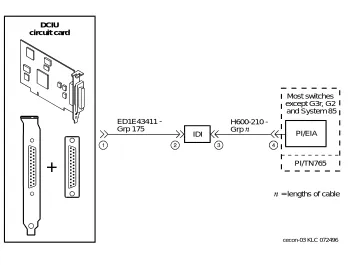
Connections through an IDI
than 15 meters (50 feet) apart, use an MPDM to facilitate the connection. See ‘‘Connections through an MPDM’’ below for information on MPDM connectivity.
Hardware Required for the Connection
■ One IDI
■ One ED-1E43411-Group 175 cable
■ One H600-210 cable, Group 1 through 7. The group depends on cable length.
■ One gender-changer for the DCIU circuit card (comcode 406783613; shipped with the circuit card)
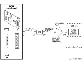
■ For a DEFINITY G3r or R5/6r only, one H600-347, Group 1 cable (male 50-pin Amphenol to four RS-232C male connectors)
Figure 1-1. System 75, G1, G3i, G3s, and G3vs IDI Connection to the Switch = lengths of cable
Most switches except G3r, G2 and System 85
PI/EIA
PI/TN765 IDI
ED1E43411 -Grp 175
H600210 -Grp
cecon-03 KLC 072496 DCIU
DCIU Switch Connections
Figure 1-2. DEFINITY G3r IDI Connection to the Switch
= lengths of cable G3r only
TN577 Packet gateway ED1E43411
-Grp 175
IDI
H600210 -Grp
H600347 -Grp 1
(Use one RS-232 connector)
cecon-06 KLC 072496 DCIU
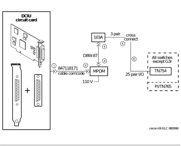
Connections through an MPDM
Use an MPDM to connect a Lucent INTUITY platform to a switch that is located more than 15 meters (50 feet) away. Figure 1-3 and Figure 1-4 show the connections for the System 75, DEFINITY G1, G3 and R5/6 switch.
Hardware Required for the Connection
■ One MPDM with an RS-232C interface card
■ One ED-1E434-1I Group 110 cable (comcode 524124658)
■ One 25-pair cable (connects the TN754 to the cross-connect field) ■ One D8W-87 4-pair module cord
■ One 103A adapter with 3-pair cord
■ Gender-changer for the DCIU circuit card (comcode 406783613; shipped with the circuit card)
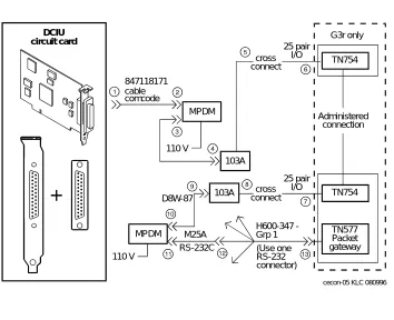
■ For a DEFINITY G3r only:
— A second 25-pair cable (connects the second TN754 to the cross-connect field)
— A second D8W-87 4-pair modular cord
— A second 103A adapter with a 3-pair cord
— A second MPDM with an RS-232C interface card
— One M25A 50-foot RS-232C male-to-female cable
DCIU Switch Connections
Figure 1-3. System 75, G1, G3, and R5/6 MPDM Connection to the Switch (Other than G3r and R5/6r)
All switches except G3r
TN754
PI/TN765 103A
847118171 cable comcode
110 V MPDM
3 pair
25 pair I/O D8W-87
cross connect
cecon-04 KLC 080996 DCIU
Figure 1-4. DEFINITY G3r MPDM Connection to the Switch
Mode Code Switch Integration
Ordinary tip and ring wiring is all that is necessary to connect INTUITY AUDIX and DEFINITY switch for mode-code integration purposes. Unlike the methods of switch integration just described, mode-code integration depends on the transmission of ordinary analog telephone signals between an INTUITY AUDIX system and a DEFINITY R6 or later switch. Signals from the INTUITY AUDIX system to the switch consist of switch-hook signals and touch-tones signals. Signals from the switch consist of call-progress signals and touch-tones signals.
Specifically, Mode-Code integration differs from DCIU integration as shown in Table 1-1. G3r only TN577 Packet gateway TN754 TN754 Administered connection 103A 847118171 cable comcode 110 V MPDM 110 V MPDM 25 pair I/O D8W-87 cross connect 25 pair I/O cross connect 103A M25A RS-232C H600347 -Grp 1 (Use one RS-232 connector)
cecon-05 KLC 080996 DCIU
Mode Code Switch Integration
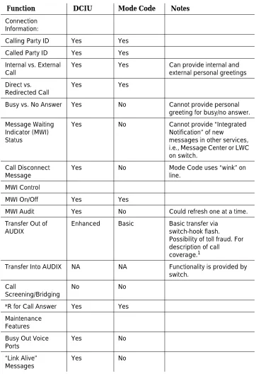
Table 1-1. Comparison of Mode Code and DCIU Integration
Function DCIU Mode Code Notes
Connection Information:
Calling Party ID Yes Yes
Called Party ID Yes Yes
Internal vs. External Call
Yes Yes Can provide internal and
external personal greetings Direct vs.
Redirected Call
Yes Yes
Busy vs. No Answer Yes No Cannot provide personal greeting for busy/no answer. Message Waiting
Indicator (MWI) Status
Yes No Cannot provide “Integrated
Notification” of new
messages in other services, i.e., Message Center or LWC on switch.
Call Disconnect Message
Yes No Mode Code uses “wink” on
line. MWI Control
MWI On/Off Yes Yes
MWI Audit Yes No Could refresh one at a time.
Transfer Out of AUDIX
Enhanced Basic Basic transfer via switch-hook flash. Possibility of toll fraud. For description of call
coverage.1
Transfer Into AUDIX NA NA Functionality is provided by switch.
Call
Screening/Bridging
No No
*R for Call Answer Yes Yes Maintenance
Features Busy Out Voice Ports
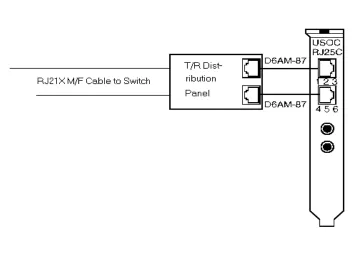
Connection through Analog Boards
Use ordinary tip and ring analog wiring to connect the messaging system to the switch. See the example that follows.
1. Run modular cables from each tip and ring board together to the tip and ring distribution panel. (See Figure 1-5.)
2. Run a 25-pair cable from the distribution panel to an analog-line circuit pack on the switch.
NOTE:
This is one of many ways to connect between the switch and messaging system using inside building wire. It is subject to the same distance limitations as stations. The key element is the connection of the T/R circuits through the 25-pair cable to the switch.
1. With “Basic Transfer”, calls transferred to the switch look like direct calls from Intuity AUDIX. They will follow the switch's coverage path for the “transfer-to” destination. With “Enhanced Transfer”, Intuity AUDIX provides the original calling and called party information, along with an indication of whether or not the switch should allow the call to follow the coverage path for the destination endpoint.
Time of Day Clock Sync
Yes No
DCS Transparency Yes No Future work for Mode Code
switches.
Digital Networking NA NA Not dependent on switch integration.
Table 1-1. Comparison of Mode Code and DCIU Integration
Mode Code Switch Integration
2
Switch Integration Planning
Overview
Before you integrate the Lucent INTUITY system with a switch, you must plan the process. This chapter provides the following worksheets and information to help you plan and record the integration:
■ Voice port information
■ Local and remote switch hunt group information ■ Remote and local data link information
■ Call coverage assignments ■ Hop channel assignments
■ Remote and host ISDN information
NOTE:
For installations outside of the United States and Canada the planning process should include a check of the default settings for country parameter administration for your location. These settings are listed in Appendix B, ‘‘Country-Specific Parameter Administration’’.
Purpose
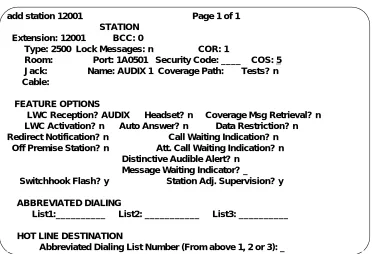
Worksheet A:
Voice Port Station
Information
Complete the information on this worksheet to collect information required to administer the Lucent INTUITY system voice ports on the switch.
Date:
Prepared By:
Contact Telephone Number:
Field Recommended Your Entry
User-Defined Adjunct Names (G3r and R5/6r only)
Enter the name you plan to use for the Lucent INTUITY system on the User Defined Adjunct Names form. You can enter a maximum of seven characters.
Extension Complete
Worksheet B: Voice Port Extensions and Names
Type ■ All DCIU:
2500
■ R6cis and other mode-cod: VMI
Port Complete
Worksheet B: Voice Port Extensions and Names
Name Complete
Worksheet B: Voice Port Extensions and Names
Lock Messages n
Coverage Path Leave blank Leave blank
Purpose
Class of Restriction (COR)
To prevent toll fraud, Lucent Technologies recommends that you create a COR for voice ports that allows users to call only other numbers with the same COR. If you later decide that users need to call numbers with different CORs, add permissions for the other CORs one at a time. The AMIS Analog Networking, Message Delivery, and Outcalling features require the ability to call numbers with different CORs.
Class of Service (COS)
Create a COS for the voice ports that permits the Data Privacy feature. Lucent Technologies recommends that you do not enable any other features on the COS.
Tests n
LWC Reception All switches:
AUDIX
Headset (System 75 and DEFINITY G1 only) n
LWC Activation n
SMDR (CDR) Privacy (not available on System 75 or G1)
n
Redirect Notification n
Off-Premise Station n
Coverage Message Retrieval n
Auto Answer n
Data Restriction n
Call Waiting Indication n
Att. Call Waiting Indication (not available on System 75 or G1)
n
Distinctive Audible Alert n
Message Waiting Indicator Leave blank Leave blank Adjunct Supervision (G3i/s only) y
R Balance Network (not available on System 75 or G1)
n
Switchhook Flash y
Message Server Name (G3r only) Leave blank Leave blank Audible Message Waiting (G3r only) n
Field Recommended Your Entry
Purpose
Worksheet B: Voice Port Extensions
and Names
Enter the location, name, and extension for each of the purchased (maximum of 64) voice ports in the following worksheet.
Date:
Prepared By:
Contact Telephone Number:
Lucent INTUITY
Port
Analog Port Equipment
Location1 Name2 Extension
1 AUDIX 1
2 AUDIX 2
3 AUDIX 3
4 AUDIX 4
5 AUDIX 5
6 AUDIX 6
7 AUDIX 7
8 AUDIX 8
9 AUDIX 9
10 AUDIX 10
11 AUDIX 11
12 AUDIX 12
13 AUDIX 13
14 AUDIX 14
15 AUDIX 15
16 AUDIX 16
17 AUDIX 17
21 AUDIX 21
22 AUDIX 22
23 AUDIX 23
24 AUDIX 24
25 AUDIX 25
26 AUDIX 26
27 AUDIX 27
28 AUDIX 28
29 AUDIX 29
30 AUDIX 30
31 AUDIX 31
32 AUDIX 32
33 AUDIX 33
34 AUDIX 34
35 AUDIX 35
36 AUDIX 36
37 AUDIX 37
38 AUDIX 38
39 AUDIX 39
40 AUDIX 40
41 AUDIX 41
42 AUDIX 42
43 AUDIX 43
44 AUDIX 44
45 AUDIX 45
46 AUDIX 46
47 AUDIX 47
48 AUDIX 48
49 AUDIX 49
50 AUDIX 50
51 AUDIX 51
Lucent INTUITY
Port
Analog Port Equipment
Location1 Name2 Extension
Purpose
1. For System 75, the equipment location is a 5-character identifier; the first character identifies the carrier, the second and third characters identify the slot number, and the fourth and fifth characters identify the port number. For example, a valid location for System 75 is B0701: carrier B, slot 07, and port 01. For all other switches, an additional 1 or 2 digits are added to the carrier, slot, and port location to identify the cabinet. For example, the location, 02B0701, specifies cabinet 02, carrier B, slot 07, port 01
2. These are the recommended names.
52 AUDIX 52
53 AUDIX 53
54 AUDIX 54
55 AUDIX 55
56 AUDIX 56
57 AUDIX 57
58 AUDIX 58
59 AUDIX 59
60 AUDIX 60
61 AUDIX 61
62 AUDIX 62
63 AUDIX 63
64 AUDIX 64
Lucent INTUITY
Port
Analog Port Equipment
Location1 Name2 Extension
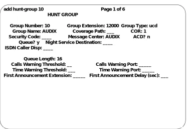
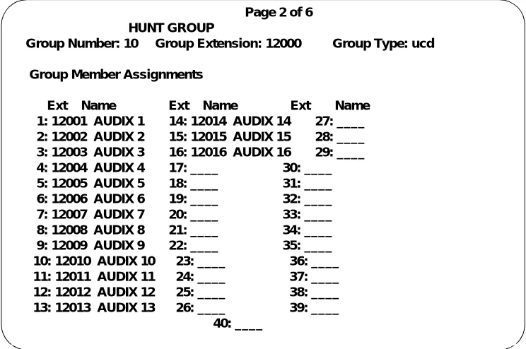
Worksheet C: Assign the Hunt Group
The following information is required to define a hunt group (containing the voice port members) for the Lucent INTUITY system voice ports.
NOTE:
Only the number of ports actually purchased should be administered in the hunt group.
Date:
Prepared By:
Contact Telephone Number:
Field Recommended Your Entry
Group Number
Enter the number you want to use to identify the Lucent INTUITY hunt group. This number, preceded by the letter “h”, is entered in the voice port Coverage Path form and in user coverage paths. Group Extension
Enter the extension number you want users to dial to retrieve their messages from the Lucent INTUITY system.
Group Type ucd
Group Name
Enter the name you want to appear on display sets when users call the Lucent INTUITY system. You must include the word “AUDIX” in the name for G3-MA to recognize the name as a Lucent INTUITY group.
Message Center AUDIX
ACD n
Queue y
Night Service Destination Leave blank Leave blank
Purpose
Vector (y/n)?
The Lucent INTUITY hunt group may be vector-controlled if call vectoring is a feature on the switch.
Security Code Leave blank Leave blank
Coverage Path Leave blank Leave blank
COR
Enter the Class of Restriction (COR) you want assigned to the extension that users will call to reach the Lucent INTUITY system. For security reasons, assign AUDIX and Lodging hunt groups their own CORs that have been restricted from accessing all outgoing trunks or only those trunks needed for Outcalling or AMIS Analog Networking. The default COR is not recommended.
ISDN Call Disp (not available on System 75 and G1)
If ISDN-PRI is enabled, enter grp-name or mbr-name to specify whether the hunt group name or number is sent to the originating user.
AUDIX Extension (System 75 R1V3 only)
This field appears only on a remote switch in a DCS network when message center is active.
The field refers to the host switch Lucent INTUITY extension number. This is the number remote Lucent INTUITY users will dial to access the hunt group. Normally this field is left blank for the Lucent INTUITY system.
Queue Length
A suggested length is the number of configured Lucent INTUITY voice ports.
Calls Warning Threshold Leave blank Leave blank Calls Warning Port Leave blank Leave blank
Time Warning Port Leave blank Leave blank First Announcement Extension (n/a for
G3r)
If you want a switch-recorded announcement, enter the extension number here.
First Announcement Delay (sec) (n/a for G3r)
This entry is optional if the queue is y and must be blank if there is no first
announcement.
Field Recommended Your Entry
Purpose
Worksheet D: Assign the Data Link for
System 75, DEFINITY G1, G3, and
R5/6 Switches (other than G3r, R5/6r
and R6cis)
Use this worksheet to plan the data link for System 75, DEFINITY G1, G3 and R5/6 switches other than R6cis, G3r, and R5/6r.
NOTE:
If you have a DEFINITY G3r or R5/6r switch, use Worksheet E: Assign the Data Link for a DEFINITY G3r or R5/6r Switch. (Integration is by audio link for the R6cis, so these worksheets do not apply.)
Section 1: MPDM Information
Complete the following section only if you plan to use an MPDM and a TN754 digital line port to connect the Lucent INTUITY system to the switch. If you do not have a connection through an MPDM, skip this section and continue with Section 2.
Date:
Prepared By:
Contact Telephone Number:
Field Recommended Your Entry
Data Extension
Type pdm
Port
Enter the port location for the TN754 that connects to the MPDM
Name
Enter the data extension name for the port that identifies the Lucent INTUITY system (such as “AUDIX” or “lodging”)
COS See Worksheet A:
COR See Worksheet A: Voice Port Station Information
Connected to dte
Remote Looparound Test n
Field Recommended Your Entry
Purpose
Section 2: Processor Interface Data Link
Information
Complete the information in this section to assign the Processor Interface data link.
Field Recommended Your Entry
Data Extension
Type ■ procr-infc
(G1, G3i/s)
■ interface (System 75) Physical Channel ■ 01 if using the
EIA port
■ 02–04 if using an MPDM
■ If two PI circuit
cards are installed, enter 05–08 if using an MPDM
Name AUDIX
COS See Worksheet A:
Voice Port Station Information
COR See Worksheet A:
Voice Port Station Information Maintenance Extension
Section 3: Processor Channel and Interface Data
Link Information
Complete the information in this section to assign the Processor Channel and Interface data link.
Field Recommended Your Entry
Processor Channel
Processor channel number Use the switch port number on the Lucent INTUITY Switch Administration screen.
Application AUDIX
Interface Link Number
Enter the same number you entered for the physical channel in Section 2 of this worksheet.
Interface Channel Number
This field contains the logical channel number of the interface link. Use the same number entered in the Logical Channel field on the Lucent INTUITY System Switch Interface Administration screen.
Use a number from 1 to 64. This field must match the number in the Remote Proc Chan field.
Priority h
Remote Proc Chan
This field contains the logical channel number of the interface link. Use the same number entered in the Logical Channel field on the Lucent INTUITY System Switch Interface Administration screen.
Use a number from 1 to 64. This field must match the Interface Channel Number field.
Machine-ID
This number must match the AUDIX Number field on the Lucent INTUITY Switch Interface Administration screen.
Purpose
Interface Link
Link
Enter the same number you entered for the physical channel in Section 2 of this worksheet.
Enable y
Est Conn y
Prot
Protocol type BX25 BX25
Destination Digits
Enter the MPDM extension if an MPDM is used or eia if link 1 is used with an IDI.
Destination Brd Leave blank Leave blank
DTE/DCE dte
Identification AUDIX
Field Recommended Your Entry
Worksheet E: Assign the Data Link
for a DEFINITY G3r or R5/6r Switch
Use this worksheet to plan the data link for a DEFINITY G3r or R5/6r switch.
NOTE:
If you have another switch, use Worksheet D: Assign the Data Link for System 75, DEFINITY G1, G3, and R5/6 Switches (other than G3r, R5/6r and R6cis) or to Chapter 6, ‘‘DEFINITY Mode-Code Switch Integration’’
Section 1: BX.25 Data Module Information
Complete the information in section to plan for assigning the BX.25 data module.
Date:
Prepared By:
Contact Telephone Number:
Field Recommended Your Entry
Name for the PGATE application
You can only change the information in this field when you add a PGATE card.
AUDIX
PGATE card location
You can only change the information in this field when you add a PGATE card. Type
You can only change the information in this field when you add a PGATE card.
BX.25
Port
Enter the PGATE port location to which the BX.25 data module connects. Name
Enter the name that identifies the Lucent INTUITY system connection
AUDIX
COR
Endpoint Type adjunct
DTE/DTC dte
Purpose
Baud Rate 9600
Error Logging n
Remote Looparound Test n
Permanent Virtual Circuit
Highest PVC Logical Channel
Switched Virtual Circuit
Layer 2 Parameters
Number of Outstanding Frames 1
Retry Attempt Counter 2
Frame Size 135
Retransmission Timer (1/10 seconds)
10
Idle timer (1/10 seconds) 30
Layer 3 Parameters
Number of Outstanding Packets 2
Restart Timer (seconds) 8
Reset Timer (seconds) 180
Field Recommended Your Entry
Section 2: Interface Link and Processor
Channel Information
Complete the information in this section to plan the Interface Link and Processor Channel assignments.
Field Recommended Your Entry
Interface Link
Link Number 1–8
Enabled y
BX.25 Extension
Enter the extension of the BX.25 data module.
Destination Number external
Establish connection Leave blank Leave blank Connected Data Module Leave blank Leave blank Identification
Enter the same name you entered in the User Defined Adjunct Name field on Worksheet A: Voice Port Station Information.
Processor Channel
Processor channel number 1–128
Application AUDIX
Interface Link Number
This entry must be the same as the Link Number set above.
Interface Channel Number
This field contains the logical channel number of the interface link. Use the same number entered in the Logical Channel field on the Lucent INTUITY System Switch Interface Administration screen.
This field must match the number in the Remote Port field.
Local Port
Use the same number entered in the Switch Port field on the Lucent INTUITY System Switch Interface Administration screen.
Purpose
Remote Port
This field contains the logical channel number of the interface link. Use the same number entered in the Logical Channel field on the Lucent INTUITY System Switch Interface Administration screen.
This field must match the number in the Interface Channel
Number field.
Adjunct Name
Enter the same name you entered in the User Defined Adjunct Name field on Worksheet A: Voice Port Station Information.
Machine-ID
Enter the Machine ID for the Lucent INTUITY system. This number must agree with the AUDIX Number field on the Lucent INTUITY Switch Interface Administration screen.
Field Recommended Your Entry
Worksheet F: Assign the Call
Coverage Path for Users
Complete this worksheet to define call coverage paths for users.
Date:
Prepared By:
Contact Telephone Number:
Field Recommended Your Entry
Coverage Path Number
Enter the number you want to identify the call coverage path for users.
Next Path Number
If desired, enter the second path to which calls will be directed if the current path fails.
Coverage Criteria
Station/Group Status Active? (Inside Call/
Outside Call)
y/y
Busy? (Inside Call/Outside Call) y/y Don’t Answer? (Inside Call/Outside Call)
y/y
All? (Inside Call/Outside Call) n/n SAC/Go to Cover? (Inside
Call/Outside Call)
y/y
Number of rings
Enter the number of rings (1–99) you want before a call goes to coverage.
3
Coverage Points
For Point1, Point2, or Point3, enter h followed by the Lucent INTUITY hunt group number.
DCS Worksheets
You have completed the worksheets and planning necessary for a Lucent INTUITY system switch integration. If you do not have a DCS environment, continue with the administration chapter for your switch. If you are placing a Lucent INTUITY system in a DCS network, continue with ‘‘DCS Worksheets’’ below.
DCS Worksheets
Complete worksheets G through P if the Lucent INTUITY system operates in a DCS environment. If you have an existing DCS network or if you are installing one, the BCS Design Center may have designed the DCS network for the Lucent INTUITY system. The worksheets in this section contain the same information the Design Center may have already created. Use these worksheets to verify that you have all required information and as a single point of reference.
This section contains worksheets for both BX.25 signaling and ISDN signaling. If the DCS network uses BX.25 signaling, complete the following worksheets:
■ Worksheet G: Remote Non-G3r, Non-R5/6r Processor Channel Assignment DCS BX.25 Signaling Information
■ Worksheet H: Remote G3r or R5/6r Processor Channel Assignment DCS BX.25 Signaling Information
■ Worksheet I: Host Hop Channel Assignment DCS BX.25 Signaling Information
■ Worksheet J: Assign the Remote Switch Hunt Group
■ Worksheet K: Assign the Call Coverage Path for DCS Remote Switches
If the DCS network uses ISDN signaling, complete the following worksheets:
■ Worksheet L: Non-G3r, Non-R5/6r Host Processor Channel Assignment ISDN Gateway Information
■ Worksheet M: G3r Host Processor Channel Assignment ISDN Gateway Information
■ Worksheet N: HOST ISDN Signaling Group Information ■ Worksheet O: Remote ISDN Signaling Group Information ■ Worksheet P: Host ISDN TSC Gateway Channel Assignment
For each remote switch in the DCS network, complete one set of DCS
Worksheet G: Remote Non-G3r,
Non-R5/6r Processor Channel
Assignment DCS
BX.25 Signaling Information
Use this worksheet to plan the remote processor channels for certain Lucent switches. Complete one copy of this worksheet for each remote switch in the DCS network.
NOTE:
If you have a DEFINITY G3r or R5/6r switch, use Worksheet H: Remote G3r or R5/6r Processor Channel Assignment DCS BX.25 Signaling Information.
Date:
Prepared By:
Contact Telephone Number:
Field Recommended Your Entry
Processor channel number 59, if available
Application AUDIX
Interface Link Number
Enter the DCS link that connects this remote switch to the host switch. Interface Channel Number
This field contains the logical channel number of the interface link. Use the number entered in the Logical Channel filed on the Lucent INTUITY Switch Interface Administration screen that represents the node number of the switch.
This field must match the number in the Remote Proc Chan field.
DCS Worksheets
Remote Proc Chan
This field contains the logical channel number of the interface link. Use the same number entered in the Logical Channel field on the Lucent INTUITY Switch Interface Administration screen that represents the node number of the switch.
This field must match the number in the Interface Channel
Number field.
Priority h
Machine-ID
Enter the Machine ID for the Lucent
INTUITY system. This number must agree with the AUDIX Number field on the Lucent INTUITY Switch Interface Administration screen.
Field Recommended Your Entry
Worksheet H: Remote G3r or R5/6r
Processor Channel Assignment DCS
BX.25 Signaling Information
Use this worksheet to plan the remote processor channels for a DEFINITY G3r or R5/6r switch. Complete one copy of this worksheet for each remote switch in the DCS network.
Date:
Prepared By:
Contact Telephone Number:
Field Recommended Your Entry
User-Defined Adjunct Names
Enter the name you entered in the User-Defined Adjunct Name field on Worksheet A: Voice Port Station Information.
Processor Channel Assignments
Processor channel number 1–128
Application AUDIX
Interface Link Number
Enter the DCS link that connects this remote switch to the host switch. Interface Channel Number
This field contains the logical channel number of the interface link. Use the number entered in the Logical Channel field on the Lucent INTUITY Switch Interface Administration screen that represents the node number of the switch.
This field must match the number on the Remote Port field.
DCS Worksheets
Remote Port
This field contains the logical channel number of the interface link. Use the same number entered in the Logical Channel field on the Lucent INTUITY Switch Interface Administration screen that represents the node number of the switch.
This field must match the number in the Interface Channel
Number field.
Local Port
This is the Switch Port number used on the Lucent INTUITY Switch Interface Administration screen.
Adjunct Name AUDIX
Machine-ID
Enter the Machine ID for the Lucent INTUITY system. This number must agree with the AUDIX Number field on the Lucent INTUITY Switch Interface Administration screen.
Field Recommended Your Entry
Worksheet I: Host Hop Channel
Assignment DCS BX.25 Signaling
Information
Complete this worksheet for each hop from a remote switch to the Lucent INTUITY system on the host switch.
Date:
Prepared By:
Contact Telephone Number:
Field Recommended Your Entry
Link
Enter the Interface Link from the host switch Processor Channel Assignment screen for the link that connects the remote switch to the host switch. Chan
Enter the Interface Channel from the remote switch Processor Channel Assignment screen for the channel that connects the remote switch to the Lucent INTUITY system on the host switch. Link
Enter the Interface Link from the host switch Processor Channel Assignment screen for the link that connects the host switch to the Lucent INTUITY system. Chan
Enter the Remote Processor Channel from the remote switch Processor Channel Assignment screen for the channel that connects the Lucent INTUITY system to the remote switch.
Priority
This field does not apply for G3r.
h
DCS Worksheets
Worksheet J: Assign the Remote
Switch Hunt Group
Complete this worksheet for each DCS switch-node that has mailboxes for users of the Lucent INTUITY system. The information is required to define a hunt group for the Lucent INTUITY system voice ports for a remote switch.
Date:
Prepared By:
Contact Telephone Number:
Field Recommended Your Entry
Group Number
Enter the number you plan to use to identify the remote switch Lucent INTUITY hunt group. This number, preceded by the letter “h”, is entered on the voice port Coverage Path screen for the remote switch and in remote user coverage paths.
Group Extension
Enter the extension number you want users to dial to retrieve their messages from the Lucent INTUITY system.
Group Type ucd
Group Name
Enter the name you want to appear on display sets when users call the Lucent INTUITY system. You must include the word “AUDIX” in the name for G3-MA to recognize the name as a Lucent INTUITY group.
Message Center rem-AUDIX
ACD n
Queue n
Night Service Destination Leave blank Leave blank Vector (y/n)?
The Lucent INTUITY hunt group may be
Security Code Leave blank Leave blank
Coverage Path Leave blank Leave blank
COR
Enter the COR you plan to assign to the extension users call to access the Lucent INTUITY system. For security reasons, assign a unique COR to the Lucent INTUITY hunt group that restricts access to all outgoing trunks or only those trunks needed for Outcalling or AMIS Analog Networking. Do not use the default COR.
ISDN Call Disp (not available on System 75 and G1)
If ISDN-PRI is enabled, enter grp-name or mbr-name to specify whether the hunt group name or number is sent to the originating user. AUDIX Extension
Enter the extension number assigned to the Lucent INTUITY system hunt group at the host switch on Worksheet C: Assign the Hunt Group.
Field Recommended Your Entry
DCS Worksheets
Worksheet K: Assign the Call
Coverage Path for DCS Remote
Switches
Use this worksheet to define a call coverage path for remote users in a DCS network. Complete one copy of the worksheet for each switch in the DCS network.
Date:
Prepared By:
Contact Telephone Number:
Field Recommended Your Entry
Host Switch Number
Enter the number of the host switch that connects directly to the Lucent INTUITY system.
Coverage Path Number
Enter the number you want to identify the call coverage path for users.
Next Path Number
If desired, enter a second path for calls. The field allows you to create additional coverage options. If the call does not meet the criteria for the first coverage path, the call attempts to use the second path.
Coverage Criteria
Station/Group Status Active? (Inside Call/
Outside Call)
y/y
Busy? (Inside Call/Outside Call) y/y Don’t Answer? (Inside
Call/Outside Call)
y/y
SAC/Go to Cover? (Inside Call/Outside Call)
y/y
Number of rings
Enter the number of rings (1–99) you want before a call goes to coverage.
3
Coverage Points
For Point1, Point2, or Point3, enter h followed by the Lucent INTUITY remote hunt group number.
Field Recommended Your Entry
DCS Worksheets
Worksheet L: Non-G3r, Non-R5/6r
Host Processor Channel Assignment
ISDN Gateway Information
Use this worksheet to plan the assignment of the host processor channels in a DCS through an ISDN-PRI configuration for certain Lucent switches.
NOTE:
If you have a DEFINITY G3r switch, use Worksheet M: G3r Host Processor Channel Assignment ISDN Gateway Information.
Date:
Prepared By:
Contact Telephone Number:
Field Recommended Your Entry
Processor channel number
Application isdn
Interface Link Number
Enter the Interface link from the host switch Interface Links screen for the Lucent INTUITY link.
Interface Channel Number
This field contains the logical channel number of the interface link. Use the number entered in the Logical Channel field on the Lucent INTUITY Switch Interface Administration screen that represents the node number of the switch.
This field must match the number in the Remote Port field.
Remote Proc Chan
This field contains the logical channel number of the interface link. Use the same number entered in the Logical Channel field on the Lucent INTUITY Switch Interface Administration screen that represents the node number of the switch.
This field must match the number in the Interface Channel
Number field.
Priority h
Machine-ID Leave blank Leave blank
Field Recommended Your Entry
DCS Worksheets
Worksheet M: G3r Host Processor
Channel Assignment ISDN Gateway
Information
Use this worksheet to plan the assignment of the host processor channels in a DCS through an ISDN-PRI configuration for a DEFINITY G3r switch.
NOTE:
If you have a System 75, DEFINITY G1, G3i, G3i-Global, G3s, or G3vs switch, see Worksheet L: Non-G3r, Non-R5/6r Host Processor Channel Assignment ISDN Gateway Information.
Date:
Prepared By:
Contact Telephone Number:
Field Recommended Your Entry
Processor channel number 1–128
Application gateway
Interface Link Number
Enter the Interface link from the host switch Interface Links form for the Lucent INTUITY link.
Interface Channel Number
This field contains the logical channel number of the interface link. Use the number entered in the Logical Channel field on the Lucent INTUITY Switch Interface Administration screen that represents the node number of the switch.
This field must match the number in the Remote Port field.
Remote Port
This field contains the logical channel number of the interface link. Use the same number entered in the Logical Channel field on the Lucent INTUITY Switch Interface Administration screen
This field must match the number in the Interface Channel
Local Port
This is the Switch Port number used on the Lucent INTUITY Switch Interface Administration screen.
Adjunct Name Leave blank Leave blank
Machine-ID
This number must agree with the AUDIX
field entry on the Lucent INTUITY Switch Interface Administration screen.
Field Recommended Your Entry
DCS Worksheets
Worksheet N: HOST ISDN Signaling
Group Information
Complete the information on this worksheet to define the ISDN signaling group for the host in a DCS/ISDN environment.
Date:
Prepared By:
Contact Telephone Number:
Field Recommended Your Entry
Group Number
Enter the number of the signaling group associated with the DCS
non-call-associated temporary signaling connection (NCA-TSC) on the remote switch.
Associated Signaling n
Primary D-channel
Enter the port number associated with the DS1 interface circuit-card port.
Secondary D-channel
Enter the port number associated with the DS1 interface circuit-card port used for secondary D-channel signaling. Max Number of NCA TSC
Increment the current field entry by 1. Max number of CA TSC
Enter the maximum number of
simultaneous Call Associated Temporary Signaling Connections (CA-TSCs) that can exist in the signaling group. Trunk Group for NCA TSC
Trunk Brd
Enter a 5-character DSI Interface circuit pack number that has trunk members belonging to this Signaling Group.
[3]
Interface ID
Enter an interface ID (0–31) for the corresponding DS1 Interface Circuit pack.
Service Feature
Enter a service type for all administered NCA-TSCs assigned in the Signaling Group.
As-needed Inactivity Time-out (min)
Enter 10–90. TSC Index
Choose a free index. Worksheet O: Remote ISDN Signaling Group Information, also contains this field. Loca