AT&T
AT&T System 25
Release 3 V3
Administration Manual
© 1989 AT&T All Rights Reserved Printed in USA
TO ORDER COPIES OF THIS DOCUMENT REFER TO DOCUMENT NUMBER 555-540-500.
Contact:
Call:
Write:
Your AT&T sales representative, or
800-432-6600, Monday to Friday between 7:30 am and 6:00 pm EST. In Canada dial 800-255-1242, or AT&T Customer Information Center
2855 North Franklin Road P.O. Box 19901
Indianapolis, Indiana 46219
Every effort was made to ensure that the information in this document was complete and accurate at the time of printing. However, this information is subject to change. This document will be reissued periodically to incorporate changes.
Administration Manual for R3 Prepared by the
FCC WARNING STATEMENT
Federal Communications commission (FCC) Rules require that you be notified of the following: ● this equipment generates, uses, and can radiate radio frequency energy and, if not installed and
used in accordance with the instruction manual, may cause interference to radio communications.
● It has been tested and found to comply with the limits for a Class A computing device pursuant to Subpart J of Part 15 of FCC Rules, which are designed to provide reasonable protection against such interference when operated in a commercial environment.
● Operation of this equipment in a residential area is likely to cause interference in which case the user at his or her own expense will be required to take whatever measures maybe required to
SECURITY OF YOUR SYSTEM—PREVENTING TOLL FRAUD
As a customer of new telephone system, you should be aware that there exists an increasing
problem of telephone toll fraud. telephone toll fraud can occur in many forms, despite the numerous efforts of telephone companies and telephone equipment manufacturers to control it. some
individuals use electronic devices to prevent or falsify records of these calls. Others charge calls to someone else’s number by illegally using lost or stolen calling cards, billing incorrect parties, clipping onto someone else’s line, and breaking into someone else’s telephone equipment physically or electronically. In certain instances, unauthorized individuals make connections to the telephone net work through the use of remove access features.
The Remote Access feature of your system, if you chose to utilize it, permits off-premises callers to access the system from a remote telephone by using an 800 number or a 7- or 10- digit telephone number. the system returns an acknowledgment signaling the user to key in his or her authorization code, which is selected and administered by the system manager. After the authorization code is accepted, the system returns dial tone to the user. If you do not program specific egress restrictions, the user will be able to place any call normally dialed from a telephone associated with the system. Such an off-premises network call is originated at, and will be billed from, the system location. The Remote Access feature, as designed, helps the customer, through proper administration, to minimize the ability of unauthorized persons to gain aces to the network. Most commonly, phone numbers and codes are compromised when overheard in a public location, through theft of a wallet or purse containing access information, or through carelessness (writing codes on a piece of paper and improperly discarding it). Additionally, hackers may use a computer to “dial” an access code and then publish the information to other hackers. Enormous charges can be run up quickly. It is the customer’s responsibility to take the appropriate steps to properly implement the features, evaluate and administer the various restriction levels, protect access codes, and distribute access codes only to individuals who have been fully advised of the sensitive nature of the access information.
Common carriers are required by law to collect their tariffed charges. While these charges are fraudulent charges made by persons with criminal intent, applicable tariffs state that the customer of record is responsible for payment of all long-distance or other network charges. AT&T cannot be responsible for such charges and will not make any allowance or give any credit for charges that result from unauthorized access.
To minimize the risk of unauthorized access to your communications system: Use a nonpublished Remote Access number.
Assign authorization codes randomly to users on a “need-to-have” basis, keeping a log of ALL authorized users and assigning one code per person.
Use random sequence authorization codes, which are less likely to be broken. Deactivate all unassigned codes promptly.
Ensure that Remote Access users are aware of their responsibility to keep the telephone numbers and any authorization codes secure.
When possible, restrict the off-network capability of off-premises callers, via use of Call Restrictions and Disallowed List capabilities.
When possible, block out-of-hours calling.
Frequently monitor system call detail reports for quicker detection of any unauthorized or abnormal calling patterns.
Limit Remote Call Forward to persons on a “need-to-know” basis.
D A N G E R
The AT&T System 25 cabinets are not user serviceable. some voltages inside the cabinet are hazardous. This equipment is to be serviced only by qualified technicians.
FCC NOTIFICATION AND REPAIR INFORMATION
Dear Customer,
This telephone equipment is registered with the Federal Communications Commission (FCC) in accordance with Part 68 of its Rules. In compliance with the Rules, be advised of the following:
1. MEANS OF CONNECTION
Connection of this telephone equipment to the nationwide telecommunications network shall be through a standard network interface jack USOC RJ21X. Connection to private line network channels requires jack USOC RJ2GX for tie lines or, jackUSOCRJ21X for off premises station lines. These can be ordered from your Telephone Company.
2. NOTIFICATION TO THE TELEPHONE COMPANY
If the system is to be connected to off-premises stations, you must notify the telephone company of the OPS Class of Service, OL13C, and the service order code, 9. OF.
NOTE: You should use the default value when administering a port on TN742 for an Off-Premises Station in order to meet the level of dial tone required for FCC compliance. Upon the request of the telephone company, you shall inform them of the following:
● The Public Switched Network “lines” (that is, your phone number) and the Private “lines” to which you will connect the telephone equipment.
● The telephone equipment’s “registration number” and “ringer equivalence number” (REN) from the label on the equipment.
● For Private Line Connections, provide the facility interface code; TL3lM for tie lines. You must also specify the service order code, 9. OF.
● The quantities and USOC numbers of the jacks required.
● For each jack, provide the sequence in which lines are to be connected; the type lines and the facility interface code and the ringer equivalence number by position when applicable. This telephone equipment should not be used on coin telephone lines. Connection to party line service is subject to state tariffs.
3. REPAIR INSTRUCTIONS
If you experience trouble with this telephone equipment, contact the AT&T National Service Center on 1-800-628-888. The Telephone Company may ask that you disconnect this equipment from the network until the problem has been corrected or until you are sure that this equipment is not malfunctioning.
4. RIGHTS OF THE TELEPHONE COMPANY
If your telephone equipment causes harm to the telephone network the Telephone Company may discontinue your service temporarily. If possible, they will notify you in advance. But if advance notice is not practical, you will be notified as soon as possible. You will be informed of your right to file a complaint with the FCC.
Your Telephone Company may make changes in its facilities, equipment, operations or procedures that could affect the proper functioning of your equipment. If they do, you will be notified in advance to give you an opportunity to maintain uninterrupted telephone service.
5. HEARING AID COMPATIBILITY
The voice terminals described in this manual are compatible with inductive y coupled hearing aids as prescribed by the FCC.
6. FCC INFORMATION
I
FCC REGISTRATION INFORMATIONRegistration Number AS593M-71565-MF-E Ringer Equivalence 0.5A
Network Interface RJ21X, RJ2GX or RJ48X
PRIVATE LINE SERVICE
Service Order Code
● Analog 9.0F
● Analog (R3) 9.0Y
● Digital (R3) 6.0Y
Facility Interface Code
● Tie Lines TL31M
● Off-Premises Stations OL13C ● Digital D4 Framing 04DU9-B
● Digital ESF 04DU9-C
System 25 Documents
The following System 25 product documents are available for your reference. Copies may be purchased from the Customer Information Center (CIC) by calling 800-432-6600. (In Canada, call 800-255-1242.)
DOCUMENT
■ R3 Administration Manual
■ An Introduction to AT&T System 25 ■ R3 Implementation Manual
■ Installation and Maintenance Manual ■ R3 Reference Manual
■ User Guides:
– Cordless Telephone User Guide – Data Features User Guide
– Direct Trunk Attendant Console User Guide — Multiline Telephone User Guide
– Single-Line Telephone User Guide – Switched Loop Attendant Console
■ Integrated Solution Documents:
– Integrated Solution User Guide
User Guide
– Integrated Solution II Administration Guide/ Installation & Maintenance Manual
– AT&T Call Accounting System Reports Guide
ORDER NUMBER 555-540-500 555-540-021 555-540-650 555-540-103 555-540-200
555-540-711 555-540-704 555-540-701 555-540-703 555-540-702 555-540-706
555-540-715 555-540-720 775-413
To expand your System 25’s communications and networking capabilities, AT&T offers the following optional software packages:
■ R3 Advanced Administration Software Package (MS-DOS) ■ R3 Advanced Administration Software Package (UNIX) ■ R3 Advanced Administration Software Package (UNIX-6386) ■ Call Management System for System 25
■ Communications Access Manager Software Package ■ STARLAN NETWORK ACCESS Software Package
Contents
1
2
3
Introduction
IntroductionImplementation Planning Forms Role of the System Administrator Using this Manual
How to Use the System
How to Use the SystemLogging In to System 25 Correcting Typing Errors Making Backup Tapes
The System 25 Administration Main Menu Administration Commands
System Responses
Initializing the System
Initializing the System Default Translations Initialization Sequence
4
Administering System-Wide Options
Administering System-Wide OptionsToll Restriction Options Coverage Options Pooled Modem Options Time of Day
Date
Call Accounting Options Miscellaneous System Options Expert Mode Prompt
Administration Password Toll Calls Allowed Lists Floating PDCs
Virtual Facilities System Speed Dialing Callback Queuing Options Remote Access Options
5
6
7
Administering Trunks
Administering TrunksAssigning a Trunk Removing a Trunk Display Support Assigning Class of Assigning COS to
Service to DID Trunks All Other Trunks
Assigning Trunk Options for a SLAC System
Administering Auxiliary Equipment
Administering Auxiliary Equipment External Alerts
Paging (Associated with Auxiliary Trunk Port) Paging (Associated with CO Trunk Port) DGC Delay Announcement
Directed Night Service Delay Announcement Music-on-Hold
VOICE POWER Voice Message System Pooled Modem
Additional Tone Detector Dictation
Administering Voice Stations
Administering Voice StationsAdding a Voice Station Display Support
Removing a Voice Station Changing a Station Dial Code Moving a Voice Station Assigning Class of Service
for Single-Line Voice Stations Assigning Class-of-Service Options for
Multiline Voice Stations (Non-Attendant)
Administering Data Line
and STARLAN CP Ports
Administering Data Line and STARLAN CP Ports Adding a Data Station
Display Support
Removing a Data Station Changing a Data Dial Code Moving a Data Station
Assigning Class-of-Service Options
9
Administering Attendant Equipment
Administering Attendant EquipmentDefault Attendant Assignments
Assigning a Switched Loop Attendant Console Assigning a Second Attendant Console Moving Attendant Consoles
Changing and Attendant PDC Checking Attendant Position Number Removing an Attendant Console
Assigning a Direct Extension Selector Console(s) 9-4 Assigning Selector Console Buttons
Direct Support
Assigning Class of Service to an Attendant Console
Assigning Attendant Options (DTAC and SLAC) 9-1 9-1 9-2 9-2 9-3 9-3 9-3 9-4 9-5 9-6 9-7 9-12
11
12
Administering Button
Assignments
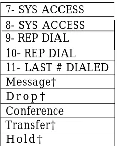
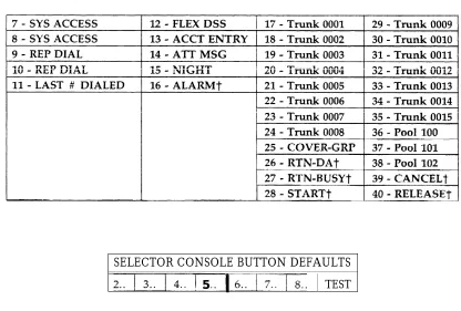
Administering Button Assignments Assigning Features to Buttons Default Button Assignments Button Assignment Tables
Assigning Buttons to Multiline Terminals and Attendant Consoles
Assigning Attendant-Console-Specific Buttons
Administering Direct Group
Calling Groups
Administering Direct Group Calling Groups
Administering Automatic Route
Selection
Administering Automatic Route Selection Automatic Route Selection Patterns Area Code Routing Table
Xl 1 Central Office Exchanges Home Area Code Exception List Other Area Code Exception List ARS Digit Translation Tables
Administering Tape Save/Restore
Operations
Administering Tape Save/Restore Operations Using the Digital Tape Unit
Save Your Translations Verify the Saved Translations
Restore the System Translations from a Backup Tape
14
15
16
17
18
System Searches
System SearchesAdministering RS-232 Parameters
Administering RS 232 ParametersCommand Reference
16 Command Reference Command ReferenceRequirements for the SAT
Requirements for the SATAdministering the T1 Carrier
Interface (DS1/Hl D CKT)
Administering the T1 Carrier Interface (DSl) TN746 Analog Line Circuit
Administration.
High Density Circuit (HI D CKT) Administration
Port Administration Timing Administration
I n d e x
Index14-1
15-1
16-1 16-3
17-1
18-1
18-1a
18-2 18-6 10-7
I-1
Introduction
This manual provides the information you need to administer AT&T System 25 station, network access, and system features. This includes configuring the system for initial service (that is, initializing the system) and making day-to-day changes required for efficient
operation. This manual is for Release 3 systems only. If you have a Release 1, Version 1 system, obtain the Administration Manual numbered 555-500-500. If you have a Release 1, Version 2 system, obtain the Administration Manual numbered 555-520-500. If you have a Release 2, Version 1 system, obtain the Administration Manual numbered 555-530-500. This manual assumes that the following considerations have been addressed.
■ You have attended the System 25 (Customer or Systems Technician) Training Course. ■ System 25 equipment has been installed and tested.
■ All stations have been tested by the Systems Technician.
■ You have available a System Administration Terminal (SAT) with which you will enter
the configuration data. (For more information, see Chapter 17, “Requirements for the SAT” .)
Implementation Planning Forms
During implementation planning, you worked with the AT&T Account Team to assign the features you need for your system and for individual terminals using the forms provided in the AT&T System 25 R3 Implementation Manual.
These forms, as explained in the Implementation Manual, provide the information necessary to enter the initial translations that customize the system. Therefore, the implementation forms must be completed before you can initialize the system. You should find the forms collected and filed in the Administration Records Binder (the binder in which the
Implementation Manual is contained).
This manual also provides instructions for making day-to-day changes after the initial translations have been entered.
NOTE: It is very important that you record these changes in the Administration Records Binder. If this is not done, future system administration will become increasingly difficult,
Role of the System Administrator
System administration involves initializing the system and administering subsequent terminal and system changes. The AT&T Systems Technician is responsible for initializing the system. At your option, the System Administrator or the systems technician may perform subsequent changes that do not require equipment additions or rearrangements. This manual is designed to support both the Systems Technician and the System Administrator.
The System Administrator is responsible for the following:
■ Training other station users and the Attendant.
■ After the system has been initialized, assuring that any additions, changes, or deletions to
system or terminal features are made. Your System Administrator may make these changes or you can contact AT&T to have the technician make the changes.
■ Maintaining system security.
■ Notifying company management (and AT&T) about problems, alarms, and service
complaints.
For more information concerning system hardware or features, refer to the AT&T System
R3 Reference Manual.
25
Using this Manual
Before you use the SAT to administer your system, you should have received hands-on training. You should also read and understand Chapter 2, “How to Use the System”, and
“Administering Tape Save/Restore Operations” in Chapter 13.
The administration procedures (chapters 4 through 15) provide detailed step-by-step
instructions for adding trunks and stations, and for changing system and station features and options. You should review the information about default trunk/station numbering in
Chapter 3 before you administer changes. Note that, when adding stations, trunks, or auxiliary equipment connected to special feature ports, you should first follow the procedure for installing the equipment, then assign Class-of-Service information and then make button assignments.
If you are initializing a system, follow the instructions in Chapter 3. It will direct you to administration procedures in a specific sequence; it is important that you perform the steps in the indicated order.
Chapter 16 provides quick reference information. The tables in that section are intended to help those who are thoroughly familiar with system administration locate specific information without having to refer to the full text in the administration procedure chapters. Unless you are an experienced System Administrator, however, you should follow the administration procedures.
Conventions Used in this Manual
The following conventions are used in this manual:
■ Commands and text you should type appear in this style of lettering.
■ System responses, such as prompts and values that appear on the screen, are shown in this style of lettering.
■ Names of Keys on the SAT keyboard appear in oval boxes. For example:press RETURN
The labels on your keyboard may vary, depending on the kind of terminal you use as an SAT.
How to Use the System
This chapter describes the way you interact with the system using the System Administration Terminal (SAT). First, it tells you how to log in to System 25. Then, how to use the Main Menu to access areas of the system you want to administer. Next, it tells you how enter administration commands to view and change the way your system operates. Finally, it describes the kinds of warning, error, and text messages the system supplies.
Logging In to System 25
System
Security
For security reasons, access to the administration capabilities of AT&T System 25 is controlled by a password. The default password is systemx5. If you want to change your password, see the instructions under “Administering System-Wide Options”.
To prevent an unauthorized person from learning the password, the password characters are not displayed when they are entered.
If system security is not a problem, because access to the SAT and to this manual are restricted, you may want to write your password here for convenience.
Otherwise, be sure to write your password down and keep it in a secure place. Entering Your Password
After you turn on the SAT, you see the following prompt:
Enter Password- >
If you do not see this prompt, Enter your password followed Invalid Password Entry
If you enter an invalid password, you see an error message followed by the password prompt:
That is not the password! Enter Password- >
Successful Log-in
When you enter the correct password, the terminal displays the Main Menu from which you can select administration functions.
Leaving an Administration Session
When you complete an administration session, or if you want to interrupt a session at any point, just turn off the terminal.
You can also end an administration session by:
■ Unplugging the cable from the modular jack connecting the terminal to the system. ■ Disconnecting the RS232 connector from the terminal.
■ Hanging up to drop the Data Terminal Ready (DTR) signal on disconnect if you are
connected via a modem.
Correcting Typing Errors
You can correct a typing error by pressing the backspace key. If your keyboard does not have a backspace key, press (sometimes abbreviated CTL or CTRL) at the same time you press h to generate the equivalent of a backspace key.
When you press the backspace key, you see a new line with the last character deleted. For example, if at the prompt you type four characters and discover that you need only the first two, you press the backspace key twice. Your terminal responds to the first backspace character by displaying a line with your last input character removed; it responds to the second by displaying the line once again with the third input character removed. You can use this technique (on both video display terminals and printing terminals) to remove unneeded characters or to replace incorrectly typed characters.
Strange Output
Under unusual circumstances (such as accidentally hitting your SAT may display highly abbreviated or unreadable responses. This indicates that the SAT is operating in a mode used for personal computer based administration or is running at the wrong speed. The best thing to do at this point is to turn off the SAT for five seconds, turn it back on, press several times, and log in again. Be sure to check the last items you were administering before proceeding. For further information, see “Requirements for the SAT”.
Making Backup Tapes
If your system is equipped with a Digital Tape Unit (DTU), it is a good idea to make backup tapes. A backup tape allows you to restore system translations if they are ever lost or damaged—from an inadvertent cold start, for example. You should make a new backup tape whenever you make changes to the system. You should save translations during off-hours, however, because that procedure may affect telephone service, and call traffic may affect save and restore operations. It is strongly recommended that you maintain a minimum of three backup tapes, updating at least two of them regularly. For more information, see
“Administering Tape Save/Restore Operations”.
The System 25 Administration Main Menu
When you log into the administration terminal, you see the Main Menu. This menu allows you to enter one of several command areas (Port, PDC, etc.). The Main Menu looks like this (you may find minor variations on your display):
MAIN MENU
1) PORT 7) TOLL ALLOWED LIST
2) PDC 8) SEARCH
3) HIDCKT 9) SAVE/RESTORE
4) SYSTEM 10) RS232
5) FPDC 11) ARS
6) DGC 12) reserved
Make one selection from menu ->
SCREEN 2-1 Main Menu
When you select an item from the Main Menu, you enter a command area consisting of action items and data items. The action and data items are used to access specific system parameters and features. Some command areas require an additional target parameter. These are discussed in detail in the “Command Formats” section.
Main Menu Items
The following list describes the features and parameters you can administer through each of the Main Menu items:
P O R T :
P D C :
H I D C K T :
S Y S T E M :
D G C :
S E A R C H :
SAVE/RESTORE:
R S 2 3 2 :
A R S :
reserved:
November 1995
Allows you to administer station, trunk, data port, or special port parameters by physical port number. A physical port number is written in the form CSSPP, where C is the l-digit cabinet number, SS is the 2-digit slot number, and PP is the 2-digit port number.
Allows you to administer station parameters by Personal Dial Code (PDC) or Data Dial Code (DDC). PDCs and DDCs are similar to extension numbers.
Allows you to administer the DS1 and 16 port SLS circuit.
Allows you to administer system-wide parameters FPDC: Allows you to administer Floating PDC numbers
Allows you to administer Direct Group Calling (DGC) groups. TOLL ALLOWED LIST: Allows you to administer Toll Calls Allowed (TCA) Lists.
Allows you to search various groups of system parameters as well as review a log of system detected errors.
Allows you to write translations to, read translations from, and compare the system translations to translations on the DTU. Allows you to assign Administration, DTU, and Station Message Detail Recording (SMDR) port options.
Allows you to administer Automatic Route Selection (ARS). (Reserved for future expansion.)
Selecting a Main Menu Item
To select an item from the Main Menu, just type the number of the item you want followed by
[
Enter <]
.● If you type
[
Enter<]
by itself or if you type a number that is not between 1 and 12, the following message is displayed.Must be a number from 1-12
Make one selection from menu->
Once you select an item from the Main Menu, you can administer the features and parameters accessible in that command area by entering commands. You use commands to tell the system what feature or parameter you want to change and the value you want to change it to. The basic format of a system administration command consists of two items: an action number, and a data
value. Some commands also require a third information number, a target. The functions of these command items are described below:
■ Action: An action number defines a specific system administration function. You choose an action (by number) to examine or change System 25 attributes.
■ Data: A data value controls a specific System 25 function. In general, a data value is the current value of the parameter specified by the associated action number. To change an administration parameter, you change its data value.
■ Target: A target can be any one of the following - PDC
- DDC - Port number - DGC number - TCA List number - RS232 Channel number.
NOTE: The words “Action” and “Data” actually appear on command lines. The word “Target” does not appear on a command line instead, the target type (e.g., Port, as shown below) is displayed.
The following example shows the format of a completed command line for the Port command area (Main Menu item 1):
Port = 10401 Action= 1 Data= 201
In this command line, Port= 10401 tells the system to go to cabinet 1, slot 04, port 01—the
physical location of the port. Action= 1 tells the system to administer the type of terminal. In this
case, Data =20 I indicates a single-line voice terminal without a message waiting indicator. If you wanted to make this station a single-line voice terminal with a message waiting indicator, you would change the data value to 202. (Action numbers and data values for all command areas appear in tables in Chapter 16, “Command Reference”.)
Command Functions
The previous section introduced you to the basic command formats. This section shows you how to enter or change an action number, data value, or target value.
Entering Commands
Keep the following considerations about the Return key in mind as you enter commands:
■ As you will see in the section below, to “enter” information means to type the required
numbers or letters and press . The Return key is included in the examples in this chapter to accustom you to using it. However, beginning with the administration procedures in Chapter 4, the Return key is not included. When you are instructed to enter something in an administration procedure, remember to press after entering the required information.
■ The basic, single-letter commands described below are: a for action, d for data, t for target, c for continue, and m for Main Menu. You can enter these commands at any time to access prompts and change the current action, data, target, or menu.
NOTE: You do not press after typing these commands. Changing an Action Number
The basic command format shows the current value of a parameter associated with its action number and the target (if any) that you indicated for that command.
If you want to move to another action number, type A or a on the keyboard. When see the Action = prompt, you enter the number of a valid action followed by . . Here is an example of the A command.
You see:
port = 10604 >
You enter A 7 and
> Action = 7 Port = 10604
>
Action = 1 Data = 304
see:
Action = 7 Data = O
The action numbers for all command areas are described in detail in the administration you
procedure chapters. Some commands require more than one action for their completion. These commands are described under “Action Groups” in this chapter.
Changing a Data Value
To change the data value associated with an action, first display the current value (as
described above), then type D or d on the keyboard. When you see Data = enter the new data value followed by
Here is an example of the D command. You see:
Port = 10604 Action = 7 >
Data = o
To change, you enter D 5 and see:
> Data = 5
Port = 10604 Action = 7 Data = 5 >
Changing a Target Value
You can change target values under the following Main Menu items:
■ P o r t
■ PDC ■ DGC
■ Toll Allowed List
■ RS232.
As examples, the next two sections show you how to change a target value under the Port and PDC Main Menu items. You change target values under the other command areas in the same way.
Under Port A port number describes the location of a station, trunk, data port, or special feature port. It is entered in the form CSSPP (described earlier).
If you selected Main Menu item 1 and you want to change the port you are administering, with a single-letter command. )
When you see Port = enter the new port number, followed by
Here is an example of the T (target select) command with Port (Main Menu item 1): You see:
Port = 20403 Action = 1 Data = 201 >
You enter T 20608 and see: > port = 20608
Action =
Under PDC You can modify stations by selecting the PDC Main Menu item. Instead of specifying the physical location of the port, as you did in the preceding example, you specify its PDC.
Here is an example of the T (target select) command with PDC (Main Menu item 2). You see:
PDC = 9876 Action = 1 Data = 2 0 1 >
You enter T 8765 and see: > PDC = 8765
Action =
Action Groups
Some action numbers are parts of groups. These groups are sets of closely related system parameters that need to be changed as a group. For example, when you assign a voice terminal, you must also assign a PDC. (See the example at the end of this section. ) If you change the data value for an action item and the system prompts you with another action item, you are administering an action group.
The number of actions may vary from group to group, but no group contains more than five actions. All action values within a particular group are consecutive. The system continues to prompt you for the next action item through the last action in that group.
After modifying a parameter that is part of an action group, you must complete the
modifications to the group by entering data values for the remaining action numbers. This protects System 25 from acting on partially complete data.
NOTE: If you change to an action number outside of the group you are currently in, all the data values entered for that group remain as they were before you began modifying the group. In other words, if you leave a group (by selecting an action outside the group) before entering the last data value for that group, all changes for that group are abandoned.
Here is an example of administering an action group. You see:
You enter D
NOTE:
Port = 10408 Action
201 and see:
> Data = 201
Port = 10408 Action >
Port = 10408 Action > Data =
= 1 D a t a = O
= 1 Data = 201
= 2 D a t a = 0
The fourth line of this display demonstrates how the system automatically brings up the next member of the group.
You enter 6789 and see: > Data = 6789
Port = 10408 Action = 2 Data = 6789 >
NOTE: There are no more members in this action group, so the system does not prompt for more data values.
Display Support IDs
The Display Support feature lets you enter an ID (or name) for each PDC, DDC, FPDC, DGC access code, and trunk, creating a database for use during system administration. For
systems with a Switched Loop Attendant Console (SLAC), it is essential that you enter this information. For systems with a Direct Trunk Attendant Console (DTAC), entering this information is optional.
In a SLAC system, the Display Support database provides call information to Attendants on the SLAC display. Display IDs also provide a convenient way to search for information during administration. DTAC System Administrators as well may find it helpful to use the Display Support search functions (see Action numbers 40 through 43 in Chapter 14). Keep the following parameters in mind when entering Display IDs:
■ The maximum number of Display IDs the system can store is 272.
■ Display IDs can contain 11 characters or less, and must be enclosed in double quotes.
Acceptable characters include any printable ASCII character (including spaces), except the double quote.
NOTE: Only the first 9 characters are shown on voice terminal displays.
■ To remove a Display ID, you enter two double quotes, with no space in between.
, When entering a Display ID name, it is recommended that you use the format “last name, first name”.
Procedures for entering specific Display IDs are included in the applicable administration procedure chapter.
Lists,
Searches, and
PortRemoval
Lists
Several Main Menu command areas involve administering a group or “list”. These areas are DGC, FPDC, Toll Calls Allowed List, and ARS. There are also Night Service Trunk lists under the Port and PDC Main Menu items.
Each of these areas includes a “display” action that shows the members of the list. When you select this action, the system displays the first member of the list. To see the next member in the list, type C or c to continue.
For example, if you select Main Menu item 5 (FPDC) and want to display active FPDCs, You see:
> Action =
You enter 1 and see:
> Action = 1
c to continue list, anything else to abort >
FPDC: Action= 1 Data= 6666 >
You enter C and see:
FPDC: Action = 1 Data = 7777 >
You enter C and see:
FPDC: Action = 1 Data = 8888 >
You enter C and see:
FPDC: Action = 1 Data = 9999 >
You enter C and see:
P16: END OF LIST FPDC: Action= 1 Data= O >
NOTE: YOU may also “abort” the list by typing a, d, or m.
Searches
The Search menu item is similar to the lists described above. However, most types of searches require at least two steps:
■ Action = 1 Data = [data value] to identify the type of search you want.
■ Action = 2 Data = [data value] to narrow the range of the search.
■ A few search areas require a third step, Action = 3 Data = [data value] to further narrow the range of search—for example, to just translated or untranslated ports. When you enter the type of search and the required qualifiers, you begin the actual search by typing C or c , “commence search”.
Removing Ports
When (under Port or PDC on the Main Menu) you try to remove a port from the system, there are several kinds of associations you may want to investigate before you remove that port from the system. These associations (for example, the appearance of a trunk on several station buttons or an external alert associated with a station) are called blocks. System 25 generates warning messages about these blocks so you do not perform an administration function that goes beyond your intent. For each type of association, you will see a warning message. To go on with the action, you respond to the system message
C for continue, any other key for abort . When there are no more associations with a station port you want to remove, you will see
W18: NO MORE BLOCKS.
The system displays this message system.
The next section describes system
this warning message, .
to prevent you from accidentally removing a port from the
responses, such as warning messages, in more detail.
System Responses
During an administration session, there are occasions when you may enter inappropriate information at a prompt. While System 25 does not catch all input errors, it does catch many of them. System 25 has three means of responding to incorrect input.
■ Error messages
■ Print messages
■ Warnings
Error
MessagesError messages appear in the following general form:
Error nnnn [Where nnnn is a number]
aaaaa aaaa [Where aaaaa aaaa is a message]
A second level of help is also available. If you need more information about an error message, you can type a question mark, “ ?”, at the next prompt. You will see a second message in this general form:
Error nnnn [Where nnnn is a number]
bbbbb bbbb [Where bbbbb bbbb is an expanded message]
Consider a specific example. You can only change a station PDC to a number that does not already exist in the dial plan. For example, say that you attempt to change PDC 1654 to PDC 1653, which is being used
To change a station PDC:
elsewhere.
-1 At the Main Menu prompt, enter 2 to access the PDC menu.
2 At PDC = , enter the PDC you want to change, 1654. 3 At Action = , enter 2 to tell the system you want to enter
a new PDC.
4 Type d and at Data = , enter the new dial code, 1653 . If you see:
Error 7012
inappropriate request Data =
that station may already exist.
(Continued)
5 To request additional help on this error message, type ? The second level error message is followed by a new prompt.
Error 7012
PDC already exists Data =
The system continues to prompt for correct data.
Print Messages
This kind of message is straightforward—it conveys information. A print message does not describe an error condition.
A print message appears at the end of certain search lists. For example, if you enter the Search option (item 8 from the Main Menu) and search the table of most recent system errors, you
Warning A warning
see the following message when you reach the end of that list:
P16: END OF
Messages message gives
LIST
you the opportunity to reconsider the administration activity you are about to perform. One of the more vivid possibilities for serious repercussions would be your command to cold start the system.
A cold start removes all the current translations in the system, installs default translations, and cancels all calls in progress on the system. The cold start command, which can be issued from Main Menu item 9 (Save/Restore), produces serious system disruption. (This command should be used only by qualified Systems Technicians. )
If you issue an administration command to force a system cold start, you see the following warning message:
W23: YOU ARE ABOUT TO FORCE A COLD START C for continue, any other key for abort
>
At this point, you can still change your mind and back out of the cold start action by entering any character except “C”.
Initializing the System
This section outlines the procedure for administering initial system translations (initializing the system).
To initialize the system, you must know the desired configuration. The System 25
implementation forms contain all the information necessary to initialize the system; they also form the basis for system Administration Records. These forms should be properly organized in the Administration Records Binder.
As the system is initialized, it is essential that you write all port assignments on the forms as the ports are translated. Failure to do this will make future changes and additions very difficult.
The steps outlined in the “Initialization Sequence” section should be followed in the sequence indicated to set up the system. Difficulties may arise if this sequence is not followed.
Default Translations
Two types of cold starts are possible with System 25. They differ in the extent of their default assignments. A “full default” cold start is usually reserved for an extreme system disruption, that might result from a damaged system translation tape or from replacing a memory board.
The other type of cold start is a “limited default” cold start. It assigns only system defaults (from Menu 4) to the system, leaving port assignments (Menu 1) blank. This type of cold start may be particularly useful during system initialization, if the dial plan you want to administer is greatly different from the one System 25 assigns in a full-default cold start. The next two sections describe these cold starts in more detail. For specific cold start procedures, see Action =20 under “Administering Tape Save/Restore Operations”.
Full-Default Cold Start
With a full-default cold start, System 25 assigns default dial codes and Table 3-1). As you attempt to assign dial codes to stations and trunks
trunk numbers (see following the steps outlined in Chapter 4, you may encounter error messages indicating that the numbers/codes you are trying to assign are already assigned. It may be that the default numbering plan conflicts with the one you are implementing. If this happens, change the conflicting default code by first removing the existing dial code, then replacing it with another.
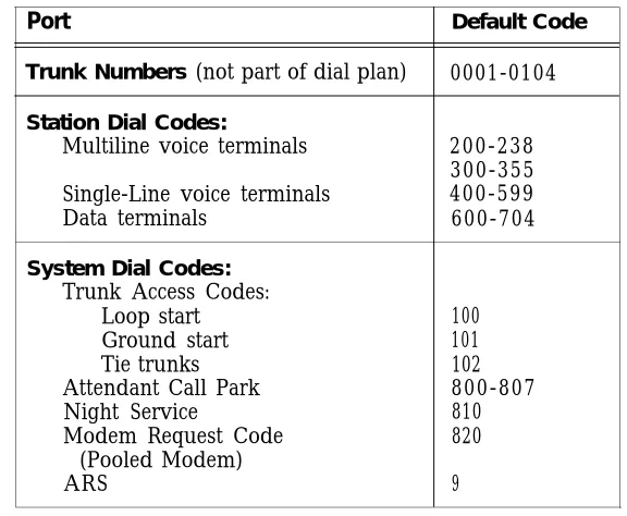
TABLE 3-1 Default Dial Code Assignments
Port Default Code
Trunk Numbers (not part of dial plan) 0001-0104 Station Dial Codes:
Multiline voice terminals 200-238 300-355 Single-Line voice terminals 400-599
Data terminals 600-704
System Dial Codes: Trunk Access Codes:
Loop start 100
Ground start 101
Tie trunks 102
Attendant Call Park 800-807
Night Service 810
Modem Request Code 820
(Pooled Modem)
ARS 9
Limited Default Cold Start
If you have many conflicting default codes, you may want to perform a limited default cold start. This type of cold start does not assign a numbering plan to the system, except for the 800-series numbers and the ARS code listed in Table 3-1. Since the system does not assign defaults for stations and trunks, it is easier for you to assign numerous new dial codes, since default-assigned dial codes do not have to be removed before you can add the new codes. A limited default cold start does assign most of the system defaults from Menu 4, except the modem request code and Central Office (CO) trunk pool access code. You need to reassign those codes after a limited default cold start. (See Action= 60 and Action= 71 in
“Administering System-Wide Options ”.) Unassigned Trunk Ports
It is also important to untranslate (or remove) any unassigned trunk ports on System 25. To untranslated, follow the procedure for removing a trunk. This tells the system that no facility is assigned to that port. Since outgoing trunk selection of pooled facilities is made in reverse order of trunk assignment (last assigned is first selected), default assigned trunks that are not actually connected to incoming facilities will result in the selection of unconnected port circuits for outgoing calls. System users will receive a reorder tone when trying to access such ports. The Circuit Pack (CP) will display a red alarm Light Emitting Diode (LED) and the attendant console will display a green alarm LED. Then you will have to untranslated the port.
Initialization Sequence
Begin with a Cold Start
When you administer the initial translations, it is important that you begin from a known condition. You can establish a known condition by forcing a cold start (Menu 9, Action= 20, Data = 1 or 2). As explained in the previous section, a full default cold start (which takes about 3 minutes) causes the system to check all slots for valid CP types and assign default translations to all ports (except auxiliary trunk ports). A limited default cold start, which takes about 30 seconds, causes the system to assign system-menu defaults but no port-specific translations.
During a full default cold start, the SAT lists all CPS in the system. When the cold start is complete, every CP (except the Memory and Auxiliary Trunk) should show a green LED; in addition, the yellow LED on the Service Circuit should be flashing or steady and the CPU green LED should be flashing. No red LEDs should be on.
When a limited default cold start is complete, the yellow LED on the Service Circuit should be flashing or steady, the CPU green LED should be flashing, and the green Tone Detector LED should be steady. NO red LEDs should be on.
If you cannot bring your system to the state you want, refer to the System 25 Installation and
Maintenance Manual before proceeding.
To Initialize the System
The implementation forms provide the information you need to complete the administration procedures in the following chapters and enter initial translations. When you initialize the system, you should accept default values for all options and parameters not listed on the implementation forms. These defaults have been chosen to provide good service for most customers.
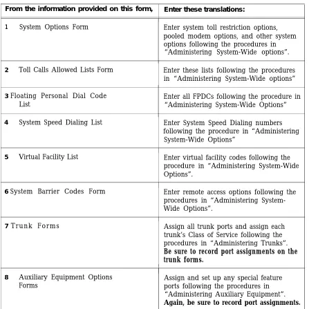
Table 3-2 lists the order of administration procedures and implementation forms you need to initialize the system.
TABLE 3-2 initialization Sequence
From the information provided on this form, Enter these translations:
1 System Options Form Enter system toll restriction options, pooled modem options, and other system options following the procedures in “Administering System-Wide options”. 2 Toll Calls Allowed Lists Form Enter these lists following the procedures
in “Administering System-Wide options” 3 Floating Personal Dial Code Enter all FPDCs following the procedure in
List “Administering System-Wide Options”
4 System Speed Dialing List Enter System Speed Dialing numbers following the procedure in “Administering System-Wide Options”
5 Virtual Facility List Enter virtual facility codes following the procedure in “Administering System-Wide Options”.
6 System Barrier Codes Form Enter remote access options following the procedures in “Administering System-Wide Options”.
7 Trunk Forms Assign all trunk ports and assign each trunk’s Class of Service following the procedures in “Administering Trunks”. Be sure to record port assignments on the trunk forms.
I
1
8 Auxiliary Equipment Options Assign and set up any special feature
Forms ports following the procedures in
“Administering Auxiliary Equipment”.
Again, be sure to record port assignments.
Continued on next page
TABLE 3-2 Initialization Sequence (continued)
From the Information provided on this form Enter these transitions:
Assign all station ports (except for attendant 9 Voice and Data Station
Records Form and consoles), following the procedures in“Administering Voice Stations” and STARLAN Interface Circuit “Administering Data Line and STARLAN
CP Ports”. Do not enter Class-of-Service parameters yet. There are some procedures you cannot complete until all stations are assigned, such as button assignments. Be sure to record each station’s port assignment on the individual voice terminal or data terminal forms as you assign them.
10 Attendant Options and Assign ports and enter Class of Service, Attendant Console Forms attendant features, and button feature
assignments for the attendant console(s) following the procedures in “Administering Attendant Equipment” and “Administering Button Assignments”.
11 Terminal Forms Enter Class-of-Service information for all voice and data stations (and button assignments for multiline voice terminals) following the procedures in “Administering Voice Stations “, “Administering Data Line and STARLAN CP Ports”, and
“Administering Button Assignments”. 12 Direct Group Calling List Enter DGC groups following the procedure
in “Administering Direct Group Calling Groups”.
13 Automatic Route Selection Enter ARS options and patterns following
Forms the procedure in “Administering Automatic
Route Selection”.
14 Dialing Options IXC code, 10 digit dial plan.
15 Tape Save/Restore Save the system translations and verify their accuracy following the procedures in “Administering Tape Save/Restore Operations”.
When you have completed these steps, the system is initialized. Be sure to test that the system is properly initialized following the procedures in the System 25 Installation and Maintenance Manual.
Administering System-Wide Options
This section describes how to set System-Wide options: ■
■ ■ ■ ■ ■ ■
■
■ ■ ■ ■ ■ ■ ■ ■
■
Toll Restrictions Coverage Pooled Modem Time of Day Date
Station Message Detail Recording Call Accounting Options
- Number of digits used for account codes Miscellaneous System Options:
- Trunk-to-trunk transfer for Loop Start trunks - Maintenance Busy for Ground Start trunks - CO trunk pool access code
- Number of DID digits used for PDCs - How to change or remove the display ID for Direct Inward Dialing (DID) trunks
Expert Mode Prompt Administration Password
Toll Calls Allowed/Disallowed Lists FPDCs
Virtual Facilities System Speed Dialing Callback Queuing Options
Remote Access Options which Include: - Remote Access Restrictions Dial Plan Options
- Equal Access (IXC) Code Format - International Dialing Option - 10-Digit Dial Plan
Toll Restriction Options
To specify your area code:
From the Main Menu prompt, enter 4, then set the following Toll Restriction options:
1 At Action=, enter 30.
2 At D a t a = , enter your area code.
To allow toll restricted stations to make toll calls within your area code:
1 At Action=, enter 31.
2 At D a t a = , enter 1 for yes or 0 for no. The default is 1.
Specify whether your CO 1 At Action=, enter 32. requires you to dial” 1”
before dialing calls 2 At D a t a = , enter 1 for yes or 0 for no. The default is 1.
outside your area code:
NOTE: This Action is ignored for 10 digit dialing only. When Action = 37, Data= 1.
Specify whether your CO requires you to dial” 1” before dialing calls within your area code:
1 At Action=, enter 33.
2 At D a t a = , enter 1 for yes or 0 for no. The default is 0 .
NOTE: This Action is ignored for 10 digit dialing only. When Action = 37, Data= 1.
To check toll restrictions on calls made over inter-PBX trunks (trunk type 805) that start with one specific digit:
1 At Action=, enter 34.
2 At D a t a = , enter the single-digit CO access code of the other PBX, 1-9 or 0 for none.
The default is 9 .
Dial Plan Options
From the Main Menu prompt, enter 4, then set the following Dial Plan options:
To identify the INPA 1 At Action =, enter 36. status for toll restriction
2 At Data=, enter checking:
- 0: for non-INPA (current numbering plan) - 1 : for INPA (NPA)
The default is 0.
(This option should not be used until the North American Dial Plan is changed to work this way. This is expected to occur in 1995.)
Equal Access (lXC) Code Format
To specify the number of 1 At Action=, enter 35. digits in the IXC code:
2 At Data=, enter - 0: 5 digit IXC code - 1: 5 or 7 digit IXC code - 2 : 7 digit IXC code The default is 0.
International Dialing
To specify the number of digits used for
international dialing:
1 At Action=, enter 38, 2 At Data =, enter
- 0: 13 digits - 1: 15 digits The default is 0.
Coverage Options
From the Main Menu prompt, enter 4, then set the following Coverage options:
To send coverage ringing 1 At Action =, enter 40. on internal calls: 2 At Data =, enter:
- 1 to provide coverage ringing on internal calls. - 0 if you do not want to provide this coverage plan. The default is 0 .
To specify the number of 1 At Action =, enter 41. rings before calls are sent 2 At Data = ,
to coverage or enter a number between 0 and 31 for the number
forwarding/following calls of rings.
The default is 2. return to their home
stations:
Pooled Modem Options
From the Main Menu prompt, enter 4, then set the following Pooled Modem options:
To specify the Modem Request Code:
1 At Action=, enter 60.
2 At D a t a = , enter a number between 1 and 9999. The default is 820.
To set the receiver to respond to remote loop:
1 At Action=, enter 61.
2 At D a t a = , enter 1 for yes or 0 for no. The default is 1 @.
To set disconnect on loss of carrier:
1 At Action =, enter 62.
2 At Data = , enter 1 for yes or 0 for no. The default is 1 @.
To set pins CF and CB as common:
1 At Action =, enter 63.
2 At D a t a = , enter 1 for yes or 0 for no. The default is 1 @.
To state whether there is disconnect on received space:
1 At Action=, enter 64.
2 At D a t a = , enter 1 for yes or 0 for no. The default is 1 @.
To state whether the 1 At Action =, enter 65.
system should send a 2 At Data = , enter 1 for yes or 0 for no. space character on
The default is 1 @. disconnect:
Time of Day
To set the time of day: 1 From the Main Menu prompt, enter 4. 2 At Action=, enter 50.
3 At D a t a = , enter the time of day in the form HHMM, where HH = hour (00 through 23) and MM = minutes (00 through 59).
@
Strongly recommended this value be used.
D a t e
To set the date: 1 From the Main Menu prompt, enter 4. 2 At Action=, enter 51 .
3 At D a t a = , enter the date in the form MMDDYY, where MM = month (01 through 12), DD - day (01 through 31), and YY = year (00 through 99).
SMDR
To specify whether SMDR records should be sent to the SMDR port:
1 From the Main Menu prompt, enter 4. 2 At Action=, enter 52.
3 At D a t a = , enter 1 for yes or 0 for no. The default is 1 @.
To specify the minimum 1 At Action=, enter 53. length (number of
2 At Data = , enter a number between 10 and 255. seconds) of calls that are
The default is 40. reported by SMDR:
To specify the type of SMDR terminal (CAT or non CAT), which is necessary because of the different capabilities of the terminals:
1 At Action=, enter 128. 2 At Data=, enter
- 0: Non-CAT terminal (default) - 1: CAT terminal
The default is 0.
@
Strongly recommended this value be used.
Call Accounting Options
Account codes: To assign 1 From the Main Menu prompt, enter 4. the number of digits used
for account codes: 2 At Action=, enter 73.
3 At D a t a = , enter a number between 1 and 15. The default is 15.
Miscellaneous System Options
From the Main Menu prompt, enter 4, then set the Systems options listed below:
To set the number of seconds before a parked call returns to the Attendant:
1 At Action=, enter 8 .
2 At D a t a = , enter the number of seconds, 0-240. The default is 120 seconds.
To enable dial tone for 1 At Action=, enter 68. incoming tie trunks:
2 At D a t a = , enter 1 for yes or 0 for no. The default is 1.
To allow trunk-to-trunk transfer for incoming Loop Start trunks:
1 At Action=, enter 69.
2 At D a t a = , enter 1 for yes or 0 for no. The default is 0 @.
To block maintenance 1 At Action=, enter 62.
busy Ground Start trunks:
2 At D a t a = , enter 1 for yes or 0 for no. The default is 0 @.
@
Strongly recommended this value be used.
To assign the CO trunk pool access code;
NOTE: This code cannot be changed after any trunks have been assigned with this facility access code.
1 At Action=, enter 71 .
2 At D a t a = , enter the CO trunk access code. The default is 100 , 101, or 102, depending on the trunk type.
To set the number of DID digits used to match against station PDCs:
1 At Action=, enter 72.
2 At D a t a = , enter a number between 2 and 4. The default is 3.
To change or remove the Display ID for DID trunks:
1 At Action=, enter 77.
2 At Data = , enter the new Display ID (11 character or less), or enter” “ to remove the Display ID.
The default is OUTSIDE.
To change or remove the 1 At Action =, enter 78. Display ID for unassigned
DID trunks: 2 At or enter” “ to remove the Display ID.Data = , enter the new Display ID ( 11 characters or less), The default is NO DID IN.
To enable maintenance- 1 At Action=, enter 80. busy for tie trunks:
2 At D a t a = , enter 1 for enable or 0 for disable. The default is 0.
To disconnect VMS: 1 At Action=, enter 96.
2 At D a t a = , enter 1 to send forward disconnect (used with VP4), or 0 to send ##99 as disconnect message (used with VPl).
The default is 0.
NOTE: VP6, VP4 = Voice boards for 6386 WGS VPl = Voice boards for 3B1.
Expert Mode Prompt
To change the expert 1 From the Main Menu prompt, enter 4. mode prompt: 2 At Action=, enter 74.
3 At Data = , enter the new prompt (nine or fewer printable
characters).
The default is Command .
Administration Password
To change the 1 From the Main Menu prompt, enter 4. administration password: 2 At Action=, enter 75.
3 At Data = , enter the new password (eight or fewer printable
characters, with no spaces). For security, the display always shows ????????.
The default is systemx5.
NOTE: The user-changeable password reverts to the default when the system cold starts. The following message is displayed when a cold start occurs:
WARNING: Default Password in effect.
Toll Calls Allowed/Disallowed Lists
There are five Toll Calls Allowed (TCA) Lists. Therefore, you must specify a target value from 1 through 5 to access these lists. The total number of entries must not exceed 164 for all 5 lists combined. Numbers can be of the form AAA (exchange within Home Area code) or NAA-AAA (Area Code plus exchange).
To disallow international calls enter in the form -OABCDE (ABC = country code, DE = first 2 digits of city code), where ABCDE could be any digit from O-9 or “.”, which is a wild card. (All subsequent digits have to be “.”.) If O + 5 dots are entered in the Toll Call disallowed list, the station(s) assigned to that class cannot make international calls.
To access a TCA list: 1 From the Main Menu prompt, enter 7.
2 At the prompt, TOLL ALLW =, enter the number, from 1
through 5, of the list you want to access.
3 Continue to administer the TCA list as described below.
To list members of a TCA 1 At Action =, enter 1 . group:
2 To continue the list, enter C after each code is printed.
To add a code to the list: 1 At Action=, enter 2 .
2 At D a t a = , enter the code number in the form AAA, NAAAAA or OAA-AAA, where:
- AAA is a 3-digit CO exchange code.
- NAA-AAA is a combination of an area code (NPA) and a CO code (optionally separated by a hyphen).
- OAA-AAA is a combination of a country code (AA-A) and a partial city code (AA).
NOTE: You can use the WILDCARD character (.). That is, you can enter AAA as AAA, AA., A.., O..., NAA..., N..., etc. All digits following a “.” must be a” .“.
To delete a code from the list:
1 At Action=, enter 3 .
2 At D a t a = , enter the code you want to delete exactly as it was listed using Action=l. .
Floating PDCs
From the Main Menu prompt, enter 5; then use the
following procedure to list, add, or delete a Floating Personal Dial Code (FPDC).
To list FPDCs: 1 At Action = , enter 1.
2 To continue the list, enter C after each FPDC is printed.
To add an FPDC: 1 At Action = , enter 2.
2 At Data = , enter the FPDC you want to add (l-9999).
To delete an FPDC: 1 At Action = , enter 3 .
2 At Data = , enter the FPDC you want to delete.
NOTE: When you remove an FPDC, any Display ID FPDC is also removed.
for that
Display Support
To assign or remove an FPDC Display ID:
1 At Action = , enter 4 .
2 At Data = , enter the FPDC,
3 Type a and at Action = , enter 5 .
4 At Data = , enter the FPDC ID (not more than 11 characters, enclosed in double quotes), or enter “” to remove the ID.
Virtual Facilities
A Virtual Facility (VF) is a call-routing facility which is not defined by the physical facility (trunk) over which calls are routed. Instead, the facility is defined by a combination of access codes, authorization codes, and coded characters that allow special handling of the
destination telephone number. VFs can be used to automatically route calls via other carrier networks, private networks, or tie trunks.
Virtual Facilities can also be used in ARS patterns to ensure that users who place these types of calls use the route (the virtual facility) the System Administrator has defined. For more information, see the System 25 R3 Reference Manual.
Keep the following parameters in mind when assigning Virtual Facility Codes (VFCs):
■ VFCs range from # 190 through # 199 (including the # sign).
■ The number you assign to a VFC can contain up to 28 digits and/or special characters. ■ You can use the following special characters within a Virtual Facility Number (VFN).
*
sends a 1.5-second pause ## - sends a ##* - sends a
*
#8 - changes signaling from dial-pulse to Touch-Tone (end-to-end signaling)
#5 - tells the system to insert the destination telephone number (dialed digits) at this point in the VFN
To assign or remove a 1 At VF:
2 At the
Action = , enter 25 .
Data = , enter the access code, 190-199 (do not enter # character).
3 To assign or remove a VFN, type a and at Action = ,
enter 26 .
4 At Data = , e n t e r :
— the number you want to assign to this VFC (allowable characters are listed at the beginning of this section). — 0 to remove the number currently displayed.
To permit dial access to 1 At Action = , enter 27 .
this- VF:
2 At Data = , enter 1 for yes or 0 for no. T h e d e f a u l t i s 0 .
System Speed Dialing
System Speed Dialing allows you to enter a four-character code at any terminal to call the associated phone number.
Keep the following considerations in mind when assigning System Speed Dialing codes:
■ Speed Dialing Codes range from # 100 through # 189 ■ The number you assign to a Speed Dialing Code can
and/or special characters.
■ You can use the following special characters within a
(including the # sign).
contain up to 28 characters or digits
System Speed Dialing number: *
## #* #8 # 19X
-sends a 1.5-second pause sends a #
* sends a
changes signaling from dial-pulse to Touch-Tone (end-to-end signaling)
embeds a Virtual Facility Code ( # 190 through # 199) as the first part of a Speed Dialing Code. (You cannot embed another Speed Dialing Code within
a Speed Dialing Code. )
NOTE: It is a good practice to remove any unused speed dialing numbers (using the
following procedure).
To administer System From the Main Menu prompt, enter 4 ; then follow the Speed Dialing: procedure below to assign or remove a System Speed Dialing
number.
Enter or remove a number from the Speed Dialing list:
1 At Action = , enter 25,
2 At Data = , enter the access code— a number between 100 and 189 (do not enter the # sign).
3 To assign or remove the speed dialing number associated with this code, enter a and at Action = , enter 26 .
At
—
Data = , enter:
the number you want to assign to this access code (allowable Speed Dialing characters are listed at the beginning of this section).
0 to remove the number currently displayed.
Callback Queuing Options
To specify the maximum 1 At Action = , enter 100 . queue size for outgoing
facilities: 2 At Data = , enter the maximum number of calls, 1-64, that can be simultaneously queued for outgoing facilities. The default is 64 @.
(Enter 0 to disable Callback Queuing for outgoing facilities. )
To specify the maximum queue size for internal facilities:
1 At Action = , enter 101 .
2 At Data = , enter the maximum number of calls, 1-64, that can be simultaneously queued for internal facilities. The default is 64 @.
(Enter 0 to disable Callback Queuing for internal facilities. )
To specify the minimum amount of time (in
seconds) between callback retries for internal
facilities:
1