1200321L1
ATLAS 890 Chassis
1200322L1
System Controller Module
1200344L1
AC Power Supply
1200345L1
DC Power Supply
Any brand names and product names included in this manual are trademarks, registered trademarks, or trade names of their respective holders.
To the Holder of the Manual
The contents of this manual are current as of the date of publication. ADTRAN reserves the right to change the contents without prior notice.
In no event will ADTRAN be liable for any special, incidental, or consequential damages or for commercial losses even if ADTRAN has been advised thereof as a result of issue of this publication.
901 Explorer Boulevard P.O. Box 140000 Huntsville, AL 35814-4000
Phone: (256) 963-8000
©2001 ADTRAN, Inc. All Rights Reserved.
operation, and maintenance of the ATLAS 890. This manual is arranged so that needed information can be quickly and easily found. The following is an overview of the contents.
Section 1
System Description
Provides managers with an overview of the ATLAS 890 system.
Section 2
Engineering Guidelines
Provides information to assist network designers with incorporating the ATLAS 890 system into their networks.
Section 3
Network Turnup Procedure
Provides step-by-step instructions on how to install the ATLAS 890 unit, determine the parameters for the system, install the network and option modules, and power up the system.
Section 4
User Interface Guide
Explains the VT-100 and Telnet interfaces, the VT-100 user interface conventions, and the ATLAS 890 top-level menu tree.
Section 5
Detail Level Procedures (DLP)
Provides the detail level procedures called out in Section 3, NTP.
Section 6
System Event Logging
Explains the System Event Logging messages for the ATLAS 890 and provides instructions for configuring the Event Log.
Glossary
Revision History
Safety Instructions
When using your telephone equipment, please follow these basic safety precautions to reduce the risk of fire, electrical shock, or personal injury:
1. Do not use this product near water, such as a bathtub, wash bowl, kitchen sink, laun-dry tub, in a wet basement, or near a swimming pool.
2. Avoid using a telephone (other than a cordless-type) during an electrical storm. There is a remote risk of shock from lightning.
3. Do not use the telephone to report a gas leak in the vicinity of the leak.
4. Use only the power cord, power supply, and/or batteries indicated in the manual. Do not dispose of batteries in a fire. They may explode. Check with local codes for spe-cial disposal instructions.
Save These Important Safety Instructions
Cautions signify information that could prevent service interruption.
transmitted on the network.
• The affidavit shall affirm that either no encoded analog content or billing information is being trans-mitted or that the output of the device meets Part 68 encoded analog content or billing protection spec-ifications.
• End user/customer will be responsible for filing an affidavit with the local exchange carrier when con-necting unprotected customer premise equipment (CPE) to 1.544 Mbps or subrate digital services. • Until such time as subrate digital terminal equipment is registered for voice applications, the affidavit
to 1.544 Mbps and/or Subrate Digital Services
For the work to be performed in the certified territory of ___________________(telco name)
State of ________________
County of ________________
I, _______________________ (name), _____________________________(business address),
____________________ (telephone number) being duly sworn, state:
I have responsibility for the operation and maintenance of the terminal equipment to be
connected to 1.544 Mbps and/or ________ subrate digital services. The terminal equipment
to be connected complies with Part 68 of the FCC rules except for the encoded analog
content and billing protection specifications. With respect to encoded analog content and
billing protection:
( ) I attest that all operations associated with the establishment, maintenance, and adjustment of
the digital CPE with respect to analog content and encoded billing protection information
con-tinuously complies with Part 68 of the FCC Rules and Regulations.
( ) The digital CPE does not transmit digital signals containing encoded analog content or billing
information which is intended to be decoded within the telecommunications network.
( ) The encoded analog content and billing protection is factory set and is not under the control of
the customer.
I attest that the operator(s)/maintainer(s) of the digital CPE responsible for the
establish-ment, maintenance, and adjustment of the encoded analog content and billing information
has (have) been trained to perform these functions by successfully having completed one of
the following (check appropriate blocks):
( ) A. A training course provided by the manufacturer/grantee of the equipment used to encode
analog signals; or
( ) B. A training course provided by the customer or authorized representative, using training
materials and instructions provided by the manufacturer/grantee of the equipment used to
encode analog signals; or
( ) C. An independent training course (e.g., trade school or technical institution) recognized by
the manufacturer/grantee of the equipment used to encode analog signals; or
_________________________________Signature
_________________________________Title
_________________________________ Date
Transcribed and sworn to before me
This ________ day of _______________, _______
_________________________________
Notary Public
My commission expires:
1. This equipment complies with Part 68 of FCC rules. On the back of the equipment housing is a label showing the FCC registration number and ringer equivalence number (REN). If requested, provide this information to the telephone company.
2. If this equipment causes harm to the telephone network, the telephone company may temporarily dis-continue service. If possible, advance notification is given; otherwise, notification is given as soon as possible. The telephone company will advise the customer of the right to file a complaint with the FCC.
3. The telephone company may make changes in its facilities, equipment, operations, or procedures that could affect the proper operation of this equipment. Advance notification and the opportunity to main-tain uninterrupted service are given.
4. If experiencing difficulty with this equipment, please contact ADTRAN for repair and warranty infor-mation. The telephone company may require this equipment to be disconnected from the network until the problem is corrected or it is certain the equipment is not malfunctioning.
5. This unit contains no user-serviceable parts.
6. An FCC compliant telephone cord with a modular plug is provided with this equipment. This equip-ment is designed to be connected to the telephone network or premises wiring using an FCC compati-ble modular jack, which is Part 68 compliant.
7. The following information may be required when applying to the local telephone company for a dial-up line for the V.34 modem:
8. The REN is useful in determining the quantity of devices you may connect to your telephone line and still have all of those devices ring when your number is called. In most areas, the sum of the RENs of all devices should not exceed five. To be certain of the number of devices you may connect to your line as determined by the REN, call your telephone company to determine the maximum REN for your calling area.
9. This equipment may not be used on coin service provided by the telephone company. Connection to party lines is subject to state tariffs. Contact your state public utility commission or corporation com-mission for information.
Service Type REN FIC USOC
uses, and can radiate radio frequency energy and, if not installed and used in accordance with the instruc-tion manual, may cause harmful interference to radio frequencies. Operainstruc-tion of this equipment in a resi-dential area is likely to cause harmful interference in which case the user will be required to correct the interference at his own expense.
Canadian Emissions Requirements
This digital apparatus does not exceed the Class A limits for radio noise emissions from digital apparatus as set out in the interference-causing equipment standard entitled “Digital Apparatus,” ICES-003 of the Department of Communications.
Cet appareil nuerique respecte les limites de bruits radioelectriques applicables aux appareils numeriques de Class A prescrites dans la norme sur le materiel brouilleur: “Appareils Numeriques,” NMB-003 edictee par le ministre des Communications.
Shielded cables must be used with this unit to ensure compliance with Class A FCC limits.
Changes or modifications to this unit not expressly approved by the party
Notice: The Canadian Industry and Science Canada label identifies certified equipment. This certification means that the equipment meets certain telecommunications network protective, operational, and safety requirements. The Department does not guarantee the equipment will operate to the user’s satisfaction.
Before installing this equipment, users should ensure that it is permissible to be connected to the facilities of the local telecommunications company. The equipment must also be installed using an acceptable method of connection. In some cases, the company’s inside wiring associated with a single line individual service may be extended by means of a certified connector assembly (telephone extension cord). The cus-tomer should be aware that compliance with the above limitations may not prevent degradation of service in some situations.
Repairs to certified equipment should be made by an authorized Canadian maintenance facility designated by the supplier. Any repairs or alterations made by the user to this equipment, or equipment malfunctions, may give the telecommunications company cause to request the user to disconnect the equipment.
Users should ensure for their own protection that the electrical ground connections of the power utility, telephone lines and internal metallic water pipe system, if present, are connected together. This precaution may be particularly important in rural areas.
The Load Number (LN) assigned to each terminal device denotes the percentage of the total load to be con-nected to a telephone loop which is used by the device, to prevent overloading. The termination on a loop may consist of any combination of devices subject only to the requirement that the total of the Load Num-bers of all devices does not exceed 100.
Return Material Authorization (RMA) is required prior to returning equipment to ADTRAN.
For service, RMA requests, or further information, contact one of the numbers listed at the end of this sec-tion.
LIMITED PRODUCT WARRANTY
ADTRAN warrants that for five (5) years from the date of shipment to Customer, all products manufac-tured by ADTRAN will be free from defects in materials and workmanship. ADTRAN also warrants that products will conform to the applicable specifications and drawings for such products, as contained in the Product Manual or in ADTRAN's internal specifications and drawings for such products (which may or may not be reflected in the Product Manual). This warranty only applies if Customer gives ADTRAN writ-ten notice of defects during the warranty period. Upon such notice, ADTRAN will, at its option, either repair or replace the defective item. If ADTRAN is unable, in a reasonable time, to repair or replace any equipment to a condition as warranted, Customer is entitled to a full refund of the purchase price upon return of the equipment to ADTRAN. This warranty applies only to the original purchaser and is not trans-ferable without ADTRAN's express written permission. This warranty becomes null and void if Customer modifies or alters the equipment in any way, other than as specifically authorized by ADTRAN.
EXCEPT FOR THE LIMITED WARRANTY DESCRIBED ABOVE, THE FOREGOING CONSTI-TUTES THE SOLE AND EXCLUSIVE REMEDY OF THE CUSTOMER AND THE EXCLUSIVE LIA-BILITY OF ADTRAN AND IS IN LIEU OF ANY AND ALL OTHER WARRANTIES (EXPRESSED OR IMPLIED). ADTRAN SPECIFICALLY DISCLAIMS ALL OTHER WARRANTIES, INCLUDING (WITHOUT LIMITATION), ALL WARRANTIES OF MERCHANTABILITY AND FITNESS FOR A PARTICULAR PURPOSE. SOME STATES DO NOT ALLOW THE EXCLUSION OF IMPLIED WARRANTIES, SO THIS EXCLUSION MAY NOT APPLY TO CUSTOMER.
In no event will ADTRAN or its suppliers be liable to Customer for any incidental, special, punitive, exemplary or consequential damages experienced by either
Customer or a third party (including, but not limited to, loss of data or information, loss of profits, or loss of use). ADTRAN is not liable for damages for any cause
ADTRAN will replace or repair this product within five years from the date of shipment if the product does not meet its published specification, or if it fails while in service.
A return material authorization (RMA) is required prior to returning equipment to ADTRAN. For service, RMA requests, training, or more information, see the toll-free contact numbers given below.
Presales Inquiries and Applications Support
Please contact your local distributor, ADTRAN Applications Engineering, or ADTRAN Sales:
Post-Sale Support
Please contact your local distributor first. If your local distributor cannot help, please contact ADTRAN Technical Support and have the unit serial number available.
The Custom Extended Services (ACES) program offers multiple types and levels of service plans which al-low you to choose the kind of assistance you need. For questions, call the ACES Help Desk.
Repair and Return
If ADTRAN Technical Support determines that a repair is needed, Technical Support will coordinate with the Custom and Product Service (CAPS) department to issue an RMA number. For information regarding equipment currently in house or possible fees associated with repair, contact CAPS directly at the following number:
Identify the RMA number clearly on the package (below address), and return to the following address:
ADTRAN Customer and Product Service 901 Explorer Blvd.
Huntsville, Alabama 35806
RMA # _____________ Applications Engineering
(800) 615-1176
Sales (800) 827-0807
Technical Support (888) 4ADTRAN
ACES Help Desk (888) 874-2237
cilities or at your site. For more information about training, please contact your Territory Manager or the En-terprise Training Coordinator.
Training - phone (800) 615-1176, ext. 7500
Training - fax (256) 963-6700
SYSTEM DESCRIPTION
This section of ADTRAN’s ATLAS 890 System Manual is designed for use by network engineers, planners, and designers for overview information about the ATLAS 890.
It contains general information and describes physical and operational concepts, card functions, network relationships, provisioning, testing, alarm status, and system monitoring. This section should be used in conjunction with Section 2, Engineering Guidelines, of the system manual.
System Overview . . . 2
Features and Benefits . . . 2
Configuration and Management . . . 2
Software Upgradeable . . . 2
Signaling Support . . . 3
ISDN Switch Types . . . 3
Dedicated Connection Maps . . . 3
Switched Connection Maps. . . 3
Testing . . . 3
Performance Monitoring . . . 3
Frame Relay . . . 3
PPP Switching. . . 4
Option Modules . . . 4
ATLAS 890 System Controller Module (P/N 1200322L1) . . . 4
Quad T1/PRI Option Module (P/N 1200185L3) . . . 5
Quad E1/PRA Option Module (P/N 1200264L1). . . 5
Quad Nx 56/64 Option Module (P/N 1200184L1) . . . 5
Quad USSI Option Module (P/N 4200261LX). . . 5
Octal Basic Rate ISDN Option Module (1200186L2) . . . 5
T3 Option Module (P/N 1200223L1) . . . 5
T3 Option Module with Drop and Insert Interface (P/N 1200225L1) . . . 5
8,16,24, 32 Channel Voice Compression Resource Modules (P/N 1200221Lx) . . . 5
Nx 56/64 IMUX Resource Module (P/N 1200262L1) . . . 6
HDLC Resource Module (P/N 1200222L1). . . 6
Modem-16 Resource Module (P/N 1200181L1) . . . 6
ATLAS 890
Section 1, System Description Page 2 of 6
1.
SYSTEM OVERVIEW
The ATLAS 890 is a modular, highly scalable platform that provides robust solutions for the wide-area communication needs of medium-to-large corporations and network access providers. The ATLAS 890 is an Integrated Access System with extensive support of dedicated bandwidth management and access switching.
The ATLAS 890 is a higher bandwidth version of the ATLAS 800PLUS. It contains a high-performance
CPU and powerful communications drivers which supports applications such as frame relay and call switching.
The ATLAS 890 architecture also includes a packet switching and a circuit switching bussing scheme. The result is a system capable of supporting bandwidth requirements of up to 30 T1 or Primary Rate ISDN (PRI) circuits. Designed for standalone or rackmount, the ATLAS 890 Base Unit provides 2
hot-swappable, redundant system controller slots and up to 16 expansion slots that accommodate hot-swappable option modules and up to 4 hot-swappable, redundant power supplies for a variety of applications. A 10/100BaseT Ethernet connection for IP routing and network management is standard with the ATLAS 890 System Controller Module.
With the ATLAS 890, you can consolidate your voice, data, and video applications into a single platform while optimizing wide area bandwidth and reducing equipment costs. The ATLAS 890 architecture and expansion slots allow for a variety of modules, making it one of the most versatile access systems on the market.
2.
FEATURES AND BENEFITS
The following is a brief list of ATLAS 890 features and benefits:
Configuration and Management
• VT-100 Emulation
• SNMP, per MIB II (RFC1213), DS1 MIB (RFC1406), and ADTRAN private MIBs • Telnet
• Dial up remote management via external analog modem • Six levels of password protection and privileges
Software Upgradeable
• Flash memory • TFTP download
Signaling Support
• ISDN D Channel
• Robbed bit, E&M, Ground Start, Loop Start
• Convert between Robbed Bit Signaling and ISDN D Channel • Direct Inward Dialing
ISDN Switch Types
• 5ESS™, DMS-100™, National ISDN, 4ESS™
Dedicated Connection Maps
• Up to five connection maps
• Time of day/day of week configurable • Preserves signaling through cross-connect • No effect on non-configured channels
Switched Connection Maps
• Inbound and outbound call filtering and blocking
Testing
• Local and remote: payload/line, V.54 (depending on installed modules) • Patterns: 511, QRSS, all ones, all zeros (depending on installed modules)
Performance Monitoring
• Reports: Information stored for last 24 hours in 15 minute increments • Performance statistics per TR54016, T1.403, RFC1406
• Alarm reporting per TR54016, T1.403
Frame Relay
• Routes Internet Protocol (IP) traffic between a public frame relay network, a private frame relay net-work, or a point-to-point (PPP) network and the Ethernet port.
• Concentrates IP traffic from a public or private frame relay network to one or more serial ports (V.35). The protocol passed over the serial port is frame relay (RFC 1490 encapsulation).
• Passes Systems Network Architecture (SNA), Bisync, and other legacy protocols between a public or private frame relay network and an external DTE running frame relay to ATLAS.
• Performs voice compression/decompression (G.723.1) and interfaces to either a Private Branch Ex-change (PBX) or the Public Switched Telephone Network (PSTN). (This feature requires an additional option module, the VCOM Module—P/N 1200221Lx.)
ATLAS 890
Section 1, System Description Page 4 of 6
PPP Switching
• Supports up to 100 simultaneous PPP connections.
• Performs PAP, CHAP, or EAP authentication methods on a per connection basis. • Includes keepalive functionality for PPP connections.
• Provides capability for numbered or unnumbered PPP interfaces.
3.
OPTION MODULES
The ATLAS 890 has a system controller module and 15 option modules:
• ATLAS 890 System Controller Module (P/N 1200322L1) • Quad T1/PRI Option Module (P/N 1200185L3)
• Quad E1/PRA Option Module (P/N 1200264L1) • Quad Nx 56/64 Option Module (P/N 1200184L1) • Quad USSI Option Module (P/N 4200261Lx) • Octal Basic Rate ISDN Option Module (1200186L2) • T3 Option Module (P/N 1200223L1)
• T3 Option Module with Drop and Insert Interface (P/N 1200225L1)
• 8,16,24, 32 Channel Voice Compression Resource Modules (P/N 1200221Lx) • Nx 56/64 IMUX Resource Module (P/N 1200262L1)
• HDLC Resource Module (P/N 1200222L1) • Modem-16 Resource Module (P/N 1200181L1) • Async-232 Option Module (P/N 1200182L1)
Each option module is hot-swappable with configuration restored upon replacement.
Each option module has a variety of performance and alarm status information. Several features of each module are user-configurable, although default values reflect the most common configurations. All option modules contain an extensive self-test as well as tests designed for the technology they incorporate.
ATLAS 890 System Controller Module (P/N 1200322L1)
In addition to controlling the shelf and its contents, the system controller modules serve as the user inter-face. The operator provisions and monitors all modules in the system, either locally or remotely, via the system controller interface. The system controllers provision the option cards in the shelf via the faceplate RJ-45 Admin connector of the active system controller and a VT-100 terminal (see Figure 4). Additionally, a 10/100 Base-T Ethernet interface is provided for Telnet access.
Quad T1/PRI Option Module (P/N 1200185L3)
The Quad T1/PRI Option Module provides four channelized T1 or PRI interfaces. Each interface can oper-ate independently in DS-1, DSX-1, or PRI mode, and any port can deliver timing for the system.
Quad E1/PRA Option Module (P/N 1200264L1)
The Quad E1/PRA Option Module provides four channelized E1 or PRA interfaces using a supplied 120 ohm DB-15 converter cable. The Quad E1/PRA Option Module may also be purchased to include BNC converter cables (P/N 4200264L1). This interface operates in CCS or CAS signaling mode and can deliver timing for the system.
Quad Nx 56/64 Option Module (P/N 1200184L1)
The Quad Nx 56/64 module provides four synchronous V.35 DTE ports (using supplied DB-78 to V.35 converter cables) that can operate from 56K to 2.048 Mbps in steps of 56 or 64 kbps. Any port can deliver timing for the system.
Quad USSI Option Module (P/N 4200261LX)
The Quad USSI Option Module provides four synchronous DTE ports that can operate from 56K to 2.048 Mbps in steps of 56 or 64 kbps. The DTE ports available (using adapter cables) are: 530, EIA-530A, RS-449, RS-232, and CCITT X.21. Any port can deliver timing for the system.
Octal Basic Rate ISDN Option Module (1200186L2)
The Octal Basic Rate ISDN module provides eight Basic Rate ISDN (BRI) U interfaces, each capable of operating in either NT or LT mode. Any port can deliver timing for the system.
T3 Option Module (P/N 1200223L1)
The T3 Option Module provides a single channelized T3 interface that allows bandwidth management of up to 28 T1s. Functions as a T3 DSU/CSU, M13 multiplexer, and 3/1/0 timeslot interchange DACS. The T3 clock or any of the odd T1s contained in the T3 circuit may deliver timing for the system.
T3 Option Module with Drop and Insert Interface (P/N 1200225L1)
The T3 Option Module with Drop and Insert Interface provides a single channelized T3 interface for pri-mary service and an additional drop and insert interface for passing T3 channels (in T1 pairs) to a second-ary channelized T3 device. Functions as a T3 DSU/CSU, M13 multiplexer, and 3/1/0 timeslot interchange DACS. The T3 clock or any of the odd T1s contained in the T3 circuit may deliver timing for the system.
8,16,24, 32 Channel Voice Compression Resource Modules (P/N 1200221Lx)
ATLAS 890
Section 1, System Description Page 6 of 6
Nx 56/64 IMUX Resource Module (P/N 1200262L1)
The Nx 56/64 IMUX Resource Option Module supports multiple, independent BONDING sessions with each session capable of using from 2 to 32 channels of 56K or 64K data. The Nx 56/64 IMUX Resource Module combines with other ATLAS 890 components to provide a flexible disaster recovery system.
HDLC Resource Module (P/N 1200222L1)
Certain ATLAS applications require a large number of High-level Data Link Control (HDLC) controllers beyond the 35 supplied on the system controller module. The HDLC Resource Module contains 128 HDLC controllers and is used when the application requirements call for more HDLC controllers than are provided with the other ATLAS hardware components. The HDLC Resource Module provides no physical interfaces.
Modem-16 Resource Module (P/N 1200181L1)
The Modem-16 Resource Module is a high-capacity card for the ATLAS Integrated Access System, capa-ble of processing 16 modem calls and 16 ISDN calls. Modem or ISDN calls are presented to ATLAS via one or more Primary Rate ISDN (PRI), Basic Rate ISDN (BRI), or T1 circuits. The Modem-16 Resource Module can be used in cooperation with the Safe-T-Net feature of the ATLAS 890 to provide a V.34 disas-ter recovery solution.The Modem-16 Resource Module combines with the Async-232 Module to enable dial-up access for up to 32 users. The Modem-16 Resource Module provides no physical interfaces.
Async-232 Option Module (P/N 1200182L1)
ENGINEERING GUIDELINES
C
ONTENTSEquipment Dimensions . . . 3
Power Requirements . . . 3
AC System . . . 3
DC System . . . 3
Reviewing the front Panel Design . . . 3
ACO Switch. . . 4
CRAFT Port. . . 4
Front Panel LEDs . . . 4
Reviewing the Rear Panel Design . . . 7
Admin Port . . . 8
10/100BaseT Connection . . . 8
Alarm Relay Connection . . . 9
External Input Connection. . . 9
Option Module Interfaces . . . 10
Quad T1/PRI Option Module (P/N 1200185L3) . . . 10
Quad E1/PRA Option Module (P/N 1200264L1). . . 10
Quad Nx 56/64 Option Module (P/N 1200184L1) . . . 11
Quad USSI Option Module (P/N 1200261L1) . . . 13
Octal BRI Option Module (P/N 1200186L2) . . . 17
Async-232 Option Module (P/N 1200182L1) . . . 18
T3 Option Module (P/N 1200223L1) . . . 18
T3 Drop and Insert Option Module (P/N 1200225L1) . . . 19
At-A-Glance Specifications . . . 20
F
IGURES Figure 1. ATLAS 890 Front Panel Layout . . . 3Figure 2. ATLAS 890 Rear Panel . . . 7
T
ABLES Table 1. CRAFT Port Pinout . . . 4Table 2. ATLAS 890 Front Panel Description . . . 4
Table 3. ATLAS 890 LEDs . . . 5
ATLAS 890
Section 2, Engineering Guidelines Page 2 of 22
1.
EQUIPMENT DIMENSIONS
The ATLAS 890 base unit is 17.08” W, 11.67” D, and 10.5” H and can be mounted in a 19-inch or 23-inch rack (mounting brackets included in shipment). All other equipment (option modules) fit inside the base unit.
2.
POWER REQUIREMENTS
AC System
The ATLAS 890 has a maximum power consumption of 400W and a maximum current draw of 7A regard-less of the configuration of option modules installed in the base unit.
DC System
The ATLAS 890 has a maximum power consumption of 325W and a maximum current draw of 8 amps at -48VDC regardless of the configuration of option modules installed in the base unit.
3.
REVIEWING THE FRONT PANEL DESIGN
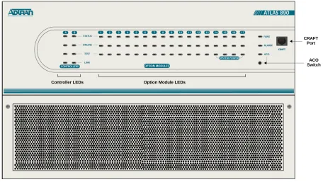
The front panel contains the Alarm Cut-off (ACO) switch, the CRAFT port, and the controller and option module status LEDs. The LEDs provide visual information about the ATLAS 890 Base Unit and any option module that may be installed. Figure 1 identifies the ACO switch, the CRAFT port, and the LEDs.
Figure 1. ATLAS 890 Front Panel Layout Controller LEDs Option Module LEDs
CRAFT Port
ATLAS 890
Section 2, Engineering Guidelines Page 4 of 22
ACO Switch
The ACO switch deactivates (clears) the Alarm Relay, located on the rear panel of the ATLAS 890, after an alarm condition has occurred. If an alarm condition is corrected and then reoccurs, the Alarm Relay will activate again.
CRAFT Port
Use the CRAFT port to configure the system via an EIA-232 connection. The connector type is shown below, and Table 1 gives the CRAFT port pinout.
Front Panel LEDs
With the ATLAS 890 powered-up, the front panel LEDs provide visual information about the status of the ATLAS 890 and any option modules that may be installed. Table 2 provides a brief description of the front panel features, and Table 3 on page 5 provides detailed information about the LEDs.
CONNECTOR TYPE RJ-48C
PART NUMBER AMP# 555164-2
Table 1. CRAFT Port Pinout
PIN NAME DESCRIPTION
1,2 UNUSED —
3 RXDATA Data received by the ATLAS 890
4 UNUSED —
5 TXDATA Data transmitted by the ATLAS 890
6,7 UNUSED —
8 UNUSED —
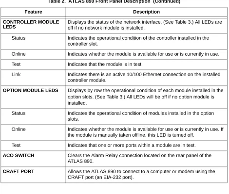
Table 2. ATLAS 890 Front Panel Description
Feature Description
SYSTEM STATUS LEDS Displays the status of the fans, alarm, and ACO buttons for ATLAS 890. (See Table 3 on page 5.)
Fans Indicates the fans are operational.
Alarm Indicates a triggered alarm condition for the alarm relays.
CONTROLLER MODULE LEDS
Displays the status of the network interface. (See Table 3.) All LEDs are off if no network module is installed.
Status Indicates the operational condition of the controller installed in the controller slot.
Online Indicates whether the module is available for use or is currently in use.
Test Indicates that the module is in test.
Link Indicates there is an active 10/100 Ethernet connection on the installed controller module.
OPTION MODULE LEDS Displays by row the operational condition of each module installed in the option slots.(See Table 3.) All LEDs will be off if no option module is installed.
Status Indicates the operational condition of modules installed in the option slots.
Online Indicates whether the module is available for use or is currently in use. If the module is manually taken offline, this LED is turned off.
Test Indicates that one or more ports within a module are in test.
ACO SWITCH Clears the Alarm Relay connection located on the rear panel of the ATLAS 890.
CRAFT PORT Allows the ATLAS 890 to connect to a computer or modem using the CRAFT port (an EIA-232 port).
Table 3. ATLAS 890 LEDs
FOR THESE LEDS... THIS COLOR LIGHT...
INDICATES THAT...
FANS Red (solid) Fan speed is too low or fan is disconnected.
Amber (solid) Fan speed is too high.
Green (solid) All fans are functioning properly.
ALARM
Red (solid) A fan, external input, or power supply error has occurred. LED will remain red until the ACO button is pressed.
ACO Amber ACO button is being pressed. Table 2. ATLAS 890 Front Panel Description (Continued)
ATLAS 890
Section 2, Engineering Guidelines Page 6 of 22
STAND-BY CONTROLLER
Status Green (slow blink) Stand-by controller is present.
Online Green (solid) Stand-by controller operational for redundancy.
Red (fast blink) Controller cannot automatically become the active controller while the current active controller is installed.
Test N/A N/A
Link Green (solid) Ethernet link detected.
ACTIVE CONTROLLER
Status Green (slow blink) Card is not ready.
Green (fast blink) Card is not supported.
Green (solid) Active controller present.
Online Amber (solid) Controller is in test mode.
Amber (fast blink) Card is upgrading firmware.
Red (fast blink) Flash parameters are not compatible.
Green (fast blink) Card is unresponsive or not supported.
Red (fast blink) Card is not ready.
Test Amber (solid) Controller is in test mode.
Link Green (solid) Ethernet link detected.
MODULE STATUS Green (solid) Module is present.
Green (fast blink) Module has been manually taken offline by the user.
Red (solid) Module failed self-test.
Red (fast blink) Module has no response, has been removed, or is not supported.
Red (slow blink) Module is not ready.
None No module occupies the slot. Table 3. ATLAS 890 LEDs (Continued)
FOR THESE LEDS... THIS COLOR LIGHT...
4.
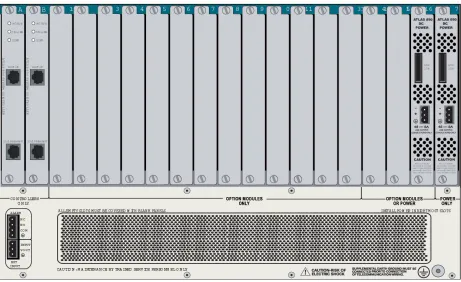
REVIEWING THE REAR PANEL DESIGN
The ATLAS 890 rear panel contains 16 slots for housing option modules which provide a variety of addi-tional resources and data ports. All slots are funcaddi-tionally identical. The ATLAS 890 also contains two slots for housing controller modules and a single slot dedicated for power supply use only (see Figure 2). The most common configuration is a fully redundant system with two system controllers and two power sup-plies. A fully redundant AC-powered ATLAS 890 provides 13 option slots. A fully redundant DC-powered ATLAS 890 provides 15 option slots.
Figure 2. ATLAS 890 Rear Panel
MODULE ONLINE Green (solid) Module has an active connection.
Green (fast blink) Module has invalid flash memory or is downloading firmware.
MODULE TEST Yellow (solid) Module is in a test mode. Table 3. ATLAS 890 LEDs (Continued)
FOR THESE LEDS... THIS COLOR LIGHT...
ATLAS 890
Section 2, Engineering Guidelines Page 8 of 22
Admin Port
The Admin port (EIA-232) connects to a computer or modem. The control port input provides the follow-ing functions:
• Accepts EIA-232 input from a PC or a modem for controlling the ATLAS 890. • Operates at 2400, 9600, 19200, or 38400 bps.
• Acts as input for either VT 100 or PC control.
• Acts as an interface for flash memory software downloads using XMODEM.
The Admin connection follows, and Table 4 shows the pinout.
10/100BaseT Connection
The 10/100BaseT port (RJ-48C) provides a 10/100BaseT Ethernet LAN connection, which is used for IP Routing, TFTP, SNMP, and Telnet connections. The network connection follows, and Table 5 shows the pinout.
CONNECTOR TYPE RJ-48C
PART NUMBER AMP# 555164-2
Table 4. Admin In Pinout
PIN NAME DESCRIPTION
1 GND Ground - connected to unit chassis
2 RTS Request to send - flow control
3 RXDATA Data received by the ATLAS 890
4 DTR Data terminal ready
5 TXDATA Data transmitted by the ATLAS 890
6 CD Carrier detect
7 UNUSED —
8 CTS Clear to send - flow control
CONNECTOR TYPE (USOC) RJ-48C
PART NUMBER AMP# 555164-2
Table 5. Ethernet Pinout
PIN NAME DESCRIPTION
1 TX1 Transmit Positive
2 TX2 Transmit Negative
Alarm Relay Connection
This connection alerts the user when a selected alarm condition exists. The four-pin, removable terminal block connects with external wiring. Refer to DLP-002, Connecting the Alarm Contacts and the External
Input for detailed instructions. Clear the alarm condition by pressing the ACO switch located on the front
panel of the ATLAS 890.
Table 6 shows the pinout for the Alarm Relay connector.
External Input Connection
This connection alerts the user when a selected external alarm condition exists. This connection could be used to monitor a UPS with dry contacts or another ATLAS 890. The three-pin, removable terminal block connects with external wiring. Refer to DLP-002, Connecting the Alarm Contacts and the External Input for detailed instructions. Clear the alarm condition by pressing the ACO switch located on the front panel of the ATLAS 890.
Table 7 shows the pinout for the External Input connector.
4, 5 UNUSED —
6 RX2 Receive Negative
7, 8 UNUSED —
Table 6. Alarm Relay Connector Pinout
Pin Name Description
1 Normally Closed (NC) Opens when a selected alarm condition is present.
2 Normally Open (NO) Closes when a selected alarm condition is present.
3 Common (COM) Common connection between external circuitry and NC or NO terminal.
4 Chassis Ground (GND)
Table 7. External Relay Monitor Connector Pinout
Pin Name Description
1 INPUT Monitors for the presence or absence of -48 VDC
2 VOUT -48 VDC @ 1 mA
3 Chassis Ground (GND)
Table 5. Ethernet Pinout (Continued)
ATLAS 890
Section 2, Engineering Guidelines Page 10 of 22
5.
OPTION MODULE INTERFACES
Quad T1/PRI Option Module (P/N 1200185L3)
Each port of the Quad T1/PRI Option Module uses a single, eight-position modular jack to connect to the T1 or PRI circuit. Table 8 gives the pinout for this jack.
Quad E1/PRA Option Module (P/N 1200264L1)
The DB-62 port of the Quad E1/PRA Option Module supplies a DB-15 connection as defined in Table 9 using provided adapter cables. The DB-62 interface pinout is shown in Table 10.
CONNECTOR TYPE (USOC) RJ-48C
Table 8. T1/PRI Pinout
PIN NAME DESCRIPTION
1 R1 RXDATA-RING Receive data from the network
2 T1 RXDATA-TIP Receive data from the network
3 — UNUSED —
4 R TXDATA-RING Send data towards the network
5 T TXDATA-TIP Send data towards the network
6,7,8 — UNUSED —
Table 9. DB-15 Connector Pinout
PIN NAME DESCRIPTION
1 RT Receive Tip
2 GND Ground
3 TT Transmit Tip
4 GND Ground
5 GND Ground
7 GND Ground
9 RR Receive Ring
Quad Nx 56/64 Option Module (P/N 1200184L1)
Each DB-78 port of the Quad Nx 56/64 Option Module supplies a V.35 Winchester-style connection as defined in Table 11 using provided adapter cables. The DB-78 interface pinout is shown in Table 12.
Table 10. DB-62 Connector Pinout
PIN NAME DESCRIPTION PIN NAME DESCRIPTION
1 P4 TT Port 4 Transmit Tip 42 GND Ground
2 P4 TR Port 4 Transmit Ring 43 P4 RT Port 4 Receive Tip
3 GND Ground 44 P4 RR Port 4 Receive Ring
6 GND Ground 45 GND Ground
7 P3 TT Port 3 Transmit Tip 48 GND Ground
8 P3 TR Port 3 Transmit Ring 49 P3 RT Port 3 Receive Tip
9 GND Ground 50 P3 RR Port 3 Receive Ring
12 GND Ground 51 GND Ground
13 P2 TT Port 2 Transmit Tip 54 GND Ground
14 P2 TR Port 2 Transmit Ring 55 P2 RT Port 2 Receive Tip
15 GND Ground 56 P2 RR Port 2 Receive Ring
18 GND Ground 57 GND Ground
19 P1 TT Port 1 Transmit Tip 60 GND Ground
20 P1 TR Port 1 Transmit Ring 61 P1 RT Port 1 Receive Tip
21 GND Ground 62 P1 RR Port 1 Receive Ring
Note: Pins that are not identified are not used. P(1-4) indicates the Port
Table 11. V.35 Winchester Pinout
Pin CCITT DESCRIPTION
A 101 Protective ground (PG)
B 102 Signal ground (SG)
C 105 Request to send (RTS) from DTE
D 106 Clear to send (CTS) to DTE
E 107 Data set ready (DSR) to DTE
F 109 Received line signal detector (DCD) to DTE
H — Data terminal ready (DTR) from DTE
ATLAS 890
Section 2, Engineering Guidelines Page 12 of 22
R 104 Received data (RD-A) to DTE
T 104 Received data (RD-B) to DTE
V 115 RX clock (RC-A) to DTE
X 115 RX clock (RC-B) to DTE
P 103 Transmitted data (TD-A) from DTE
S 103 Transmitted data (TD-B) from DTE
Y 114 TX clock (TC-A) to DTE
AA 114 TX clock (TC-B) to DTE
U 113 External TX clock (ETC-A) from DTE
W 113 External TX clock (ETC-B) from DTE
NN — Test mode (TM) to DTE
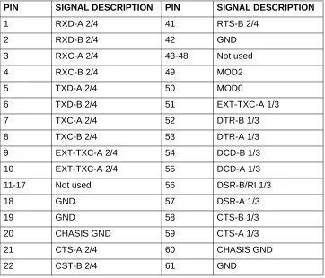
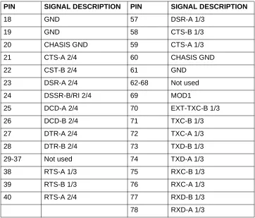
Table 12. DB-78 Pinout for the Quad Nx 56/64 Option Module
PIN SIGNAL DESCRIPTION PIN SIGNAL DESCRIPTION
1 RXD-A 2/4 41 RTS-B 2/4
2 RXD-B 2/4 42 GND
3 RXC-A 2/4 43-48 Not used
4 RXC-B 2/4 49 MOD2
5 TXD-A 2/4 50 MOD0
6 TXD-B 2/4 51 EXT-TXC-A 1/3
7 TXC-A 2/4 52 DTR-B 1/3
8 TXC-B 2/4 53 DTR-A 1/3
9 EXT-TXC-A 2/4 54 DCD-B 1/3
10 EXT-TXC-A 2/4 55 DCD-A 1/3
11-17 Not used 56 DSR-B/RI 1/3
18 GND 57 DSR-A 1/3
19 GND 58 CTS-B 1/3
20 CHASIS GND 59 CTS-A 1/3
21 CTS-A 2/4 60 CHASIS GND
22 CST-B 2/4 61 GND
Note: 1/3 or 2/4 indicates the port on the Nx 56/64 Module
Table 11. V.35 Winchester Pinout (Continued)
Quad USSI Option Module (P/N 1200261L1)
Table 13 through Table 18 show pinouts for the available interfaces for the Quad USSI Option Module and the cable part numbers required by each interface.
23 DSR-A 2/4 62-68 Not used
24 DSSR-B/RI 2/4 69 MOD1
25 DCD-A 2/4 70 EXT-TXC-B 1/3
26 DCD-B 2/4 71 TXC-B 1/3
27 DTR-A 2/4 72 TXC-A 1/3
28 DTR-B 2/4 73 TXD-B 1/3
29-37 Not used 74 TXD-A 1/3
38 RTS-A 1/3 75 RXC-B 1/3
39 RTS-B 1/3 76 RXC-A 1/3
40 RTS-A 2/4 77 RXD-B 1/3
78 RXD-A 1/3
Table 13. DB-78 Pinout for the Quad USSI Option Module
PIN SIGNAL DESCRIPTION PIN SIGNAL DESCRIPTION
1 RXD-A 2/4 41 RTS-B 2/4
2 RXD-B 2/4 42 GND
3 RXC-A 2/4 43-48 Not used
4 RXC-B 2/4 49 MOD2
5 TXD-A 2/4 50 MOD0
6 TXD-B 2/4 51 EXT-TXC-A 1/3
7 TXC-A 2/4 52 DTR-B 1/3
8 TXC-B 2/4 53 DTR-A 1/3
9 EXT-TXC-A 2/4 54 DCD-B 1/3
10 EXT-TXC-A 2/4 55 DCD-A 1/3
11-17 Not used 56 DSR-B/RI 1/3
Note: 1/3 or 2/4 indicates the port on the USSI Module
Table 12. DB-78 Pinout for the Quad Nx 56/64 Option Module (Continued)
PIN SIGNAL DESCRIPTION PIN SIGNAL DESCRIPTION
ATLAS 890
Section 2, Engineering Guidelines Page 14 of 22
18 GND 57 DSR-A 1/3
19 GND 58 CTS-B 1/3
20 CHASIS GND 59 CTS-A 1/3
21 CTS-A 2/4 60 CHASIS GND
22 CST-B 2/4 61 GND
23 DSR-A 2/4 62-68 Not used
24 DSSR-B/RI 2/4 69 MOD1
25 DCD-A 2/4 70 EXT-TXC-B 1/3
26 DCD-B 2/4 71 TXC-B 1/3
27 DTR-A 2/4 72 TXC-A 1/3
28 DTR-B 2/4 73 TXD-B 1/3
29-37 Not used 74 TXD-A 1/3
38 RTS-A 1/3 75 RXC-B 1/3
39 RTS-B 1/3 76 RXC-A 1/3
40 RTS-A 2/4 77 RXD-B 1/3
78 RXD-A 1/3
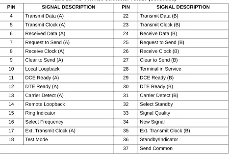
CONNECTOR TYPE EIA-530
SYSTEM PART NUMBER 4200261L2
Table 14. EIA-530 Connector Pinout
PIN SIGNAL DESCRIPTION PIN SIGNAL DESCRIPTION
1 Shield (Ground) 13 Clear to Send (B)
2 Transmit Data (A) 14 Transmit Data (B)
3 Received Data (A) 15 Transmit Clock (A)
4 Request to Send (A) 16 Received Data (B)
5 Clear to Send (A) 17 Receive Clock (A)
6 DCE Ready (A) 18 Local Loopback
7 Signal Ground 19 Request to Send (B)
8 Carrier Detect (A) 20 DTE Ready (A)
Table 13. DB-78 Pinout for the Quad USSI Option Module (Continued)
PIN SIGNAL DESCRIPTION PIN SIGNAL DESCRIPTION
9 Received Clock (B) 21 Remote Loopback
10 Carrier Detect (B) 22 DCE Ready (B)
11 Ext. Transmit Clock (B) 23 DTE Ready (B)
12 Transmit Clock (B) 24 Ext. Transmit Clock (A)
25 Test Mode
CONNECTOR TYPE EIA-530A
SYSTEM PART NUMBER 4200261L2
Table 15. EIA-530A Connector Pinout
PIN SIGNAL DESCRIPTION PIN SIGNAL DESCRIPTION
1 Shield (Ground) 13 Clear to Send (B)
2 Transmit Data (A) 14 Transmit Data (B)
3 Received Data (A) 15 Transmit Clock (A)
4 Request to Send (A) 16 Received Data (B)
5 Clear to Send (A) 17 Receive Clock (A)
6 DCE Ready (A) 18 Local Loopback
7 Signal Ground 19 Request to Send (B)
8 Carrier Detect (A) 20 DTE Ready (A)
9 Received Clock (B) 21 Remote Loopback
10 Carrier Detect (B) 22 Ring Indicator
11 Ext. Transmit Clock (B) 23 Signal Ground
12 Transmit Clock (B) 24 Ext. Transmit Clock (A)
25 Test Mode
CONNECTOR TYPE RS-449/V.36
SYSTEM PART NUMBER 4200261L1
Table 16. RS-449/V.36 Connector Pinout
PIN SIGNAL DESCRIPTION PIN SIGNAL DESCRIPTION
1 Shield (Ground) 19 Signal Ground
2 Signaling Rate Indicator 20 Receive Common
3 Not Used 21 Not Used
Table 14. EIA-530 Connector Pinout (Continued)
ATLAS 890
Section 2, Engineering Guidelines Page 16 of 22
4 Transmit Data (A) 22 Transmit Data (B)
5 Transmit Clock (A) 23 Transmit Clock (B)
6 Received Data (A) 24 Receive Data (B)
7 Request to Send (A) 25 Request to Send (B)
8 Receive Clock (A) 26 Receive Clock (B)
9 Clear to Send (A) 27 Clear to Send (B)
10 Local Loopback 28 Terminal in Service
11 DCE Ready (A) 29 DCE Ready (B)
12 DTE Ready (A) 30 DTE Ready (B)
13 Carrier Detect (A) 31 Carrier Detect (B)
14 Remote Loopback 32 Select Standby
15 Ring Indicator 33 Signal Quality
16 Select Frequency 34 New Signal
17 Ext. Transmit Clock (A) 35 Ext. Transmit Clock (B)
18 Test Mode 36 Standby/Indicator
37 Send Common
CONNECTOR TYPE RS-232
SYSTEM PART NUMBER 4200261L4
Table 17. RS-232 Connector Pinout
PIN SIGNAL DESCRIPTION PIN SIGNAL DESCRIPTION
1 Shield (Ground) 14 Sec. Transmit Data
2 Transmit Data 15 DCE Transmit Clock
3 Received Data 16 Sec. Received Data
4 Request to Send 17 Receive Signal Element Timing
5 Clear to Send 18 Not used
6 Data Set Ready 19 Sec. Request to Send
7 Signal Ground 20 Data Terminal Ready
8 Received Line Signal Detector 21 Signal Quality Detector
9 + Voltage 22 Ring Indicator
Table 16. RS-449/V.36 Connector Pinout (Continued)
Octal BRI Option Module (P/N 1200186L2)
Each port of the Octal BRI Option Module uses a single RJ-45 jack to connect to a standard BRI U inter-face circuit. Table 19 shows the network pinout connection. The required wiring connection follows:
10 - Voltage 23 Data Signal Rate Selector
11 Not used 24 DTE Transmit Clock
12 Sec. Received LIne Signal Indicator 25 Not used
13 Sec. Clear to Send
CONNECTOR TYPE CCIT X.21 V.11
SYSTEM PART NUMBER 4200261L3
Table 18. CCIT X.21 V.11 Connector Pinout
PIN SIGNAL DESCRIPTION PIN SIGNAL DESCRIPTION
1 Shield (Ground) 8 Signal Ground
2 Transmit Data (A) 9 Transmit Data (B)
3 Request to Send (A) 10 Request to Send (B)
4 Received Data (A) 11 Received Data (B)
5 Carrier Detect (A) 12 Carrier Detect (B)
6 Transmit/Receive Clock (A) 13 Transmit/Received Clock (B)
7 Ext. Transmit Clock (A) 14 Ext. Transmit Clock (B)
15 Not Used
CONNECTOR TYPE (USOC) RJ-45
Table 19. BRI Pinout
PIN NAME DESCRIPTION
1, 2, 3, 6, 7, 8 Unused —
4 Ring Ring to and from the Network Interface
5 Tip Tip to and from the Network Interface Table 17. RS-232 Connector Pinout (Continued)
ATLAS 890
Section 2, Engineering Guidelines Page 18 of 22
Async-232 Option Module (P/N 1200182L1)
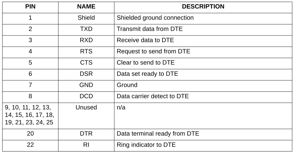
Each Async-232 Interface provides a DB-25 connection as defined in Table 20 using provided adapter cables.
T3 Option Module (P/N 1200223L1)
Each T3 Option Module provides BNC connectors for transmit and receive connections define in Table 21. Using provided RG 59, 75 ohm cables.
Table 20. DB-25 Connector Pinout
PIN NAME DESCRIPTION
1 Shield Shielded ground connection
2 TXD Transmit data from DTE
3 RXD Receive data to DTE
4 RTS Request to send from DTE
5 CTS Clear to send to DTE
6 DSR Data set ready to DTE
7 GND Ground
8 DCD Data carrier detect to DTE
9, 10, 11, 12, 13, 14, 15, 16, 17, 18, 19, 21, 23, 24, 25
Unused n/a
20 DTR Data terminal ready from DTE
22 RI Ring indicator to DTE
Table 21. T3 Module Connections
NAME DESCRIPTION
RX IN Receive data from the network, 75 ohms ± 5%, unbalanced
T3 Drop and Insert Option Module (P/N 1200225L1)
Each T3 Drop and Insert Option Module provides BNC connectors for both primary and secondary trans-mit and receive connections as defined in Table 22 using provided RG 59, 75 ohm cables.
Table 22. T3 Drop and Insert Module Connections
NAME DESCRIPTION
Primary RX IN Primary receive data from the network, 75 ohms ± 5%, unbalanced
Primary TX OUT Primary transmit data to the network, 75 ohms ± 5%, unbalanced
Secondary RX IN Secondary receive data from the network, 75 ohms ± 5%, unbalanced
ATLAS 890
Section 2, Engineering Guidelines Page 20 of 22
6.
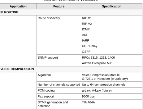
AT-A-GLANCE SPECIFICATIONS
Table 23 lists the specifications for the ATLAS 890 system.
Table 23. Specifications
Application Feature Specification
TDM APPLICATIONS
TDM bandwidth 49 Mbps Full duplex
Dedicated map connections 766 dedicated DS0 map connections in each of the 5 maps
SWITCHING APPLICATIONS
ISDN signaling types National ISDN
Lucent 5E
AT&T 4ESS (PRI Only)
Northern DMS-100 (Nortel Custom)
ETSI/DSS1
T1 signaling types Loop-Start
Ground-Start
E&M Wink
E&M Immediate
Feature Group D
DSP Features DTMF/MF tones support
Progress tone generation
32 available DSP channels
BRI Connections 128 connections
PRI Connections 766 DS0 connections
FRAME RELAY
Packet throughput 11,700 pkts/sec (64-1500 size packets)
Management signaling interfaces
UNI (user and network)
NNI
Management signaling types ANSI T1.617-D (Annex D)
ITU-T Q.933-A (Annex A)
LMI (Group of four)
Auto
Encapsulation RFC 1490
PVC support 990 PVCs per packet endpoint
Congestion control FECN / BECN
Discard eligible (DE)
Quality of service (QOS) Prioritization on a per-PVC basis
Testing (ADTRAN proprietary) PVC loopback
Round trip delay measurement
SNMP support RFC 1315
PPP
Connection support 35 PPP connections to the internal router (not exceeding 11,700 packets per second)
100 PPP connections to the internal router (requires HDLC Module and cannot exceed 11,700 packets per second)
Authentication support PAP
CHAP
EAP
Keepalive support On/Off
Interface support Numbered interfaces
Un-numbered interfaces Table 23. Specifications (Continued)
ATLAS 890
Section 2, Engineering Guidelines Page 22 of 22
IP ROUTING
Route discovery RIP V1
RIP V2
ICMP
ARP
IARP
UDP Relay
OSPF
SNMP support RFCs 1315, 1213, 1406
Adtran Enterprise MIB
VOICE COMPRESSION
Algorithm Voice Compression Module G.723.1 or Netcoder (proprietary)
Number of channels supported Up to 64 compression channels
PCM coding µ-Law, A-Law (future)
Fax support 9600 bps
DTMF generation and detection
TIA 464A Table 23. Specifications (Continued)
NETWORK TURNUP PROCEDURE
C
ONTENTSIntroduction . . . 2
Tools Required . . . 2
Unpack and Inspect the SYSTEM . . . 2 Contents of ADTRAN Shipments . . . 2
Grounding Instructions . . . 3
Supplying Power to the Unit . . . 3 AC Powered Systems . . . 3 DC Powered Systems . . . 4
Mounting Options . . . 4
Installing Network and Option Modules . . . . 5 Instructions for Installing the ATLAS 890 Controller and Option Modules . . . 5 Quad T1/PRI Option Module (P/N 1200185L3) . . . 6 Quad E1/PRA Option Module (P/N 1200264L1). . . 6 Quad Nx 56/64 Option Module (P/N 1200311L1) . . . 6 Quad USSI Option Module System (P/N 4200261LX) . . . 7 Octal Basic Rate ISDN Option Module (P/N 1200186L2) . . . 7 T3 Option Module (P/N 1200223L1) . . . 7 T3 Option Module with Drop and Insert Interface (P/N 1200225L1) . . . 7 8,16,24,32 Channel Voice Compression Resource Modules (P/N 1200221LX). . . 8 Nx 56/64 IMUX Resource Module (P/N 1200262L1) . . . 8 HDLC Resource Module (P/N 1200222L1). . . 8 Modem-16 Resource Module (P/N 1200181L1) . . . 8 Async-232 Option Module (P/N 1200182L1) . . . 8
F
IGURESATLAS 890
Section 3, Network Turnup Procedure Page 2 of 8
1.
INTRODUCTION
This section discusses the installation process of the ATLAS 890 installation.
2.
TOOLS REQUIRED
The tools required for installation of the ATLAS 890 shelf are:
• #2 Phillips-head screwdriver
• Flat-head screwdriver (for installing modules)
3.
UNPACK AND INSPECT THE SYSTEM
Each ATLAS 890 is shipped in its own cardboard shipping carton. Open each carton carefully and avoid deep penetration into the carton with sharp objects.
After unpacking the unit, inspect it for possible shipping damage. If the equipment has been damaged in transit, immediately file a claim with the carrier, then contact ADTRAN Customer Service (see Customer
Service, Product Support Information, and Training in the front of this manual).
Contents of ADTRAN Shipments
Your ADTRAN shipment includes the following items:
• The ATLAS 890 Base Unit • The ATLAS 890 System CD
• AC Power cord - ADTRAN P/N 3127031 (with AC systems) • 19-23” Convertable Rackmount brackets and screws
• RJ-45—DB-25 adapter (1 for modem connection) • RJ-45 control port cable (1) - ADTRAN P/N 3127004 • RJ-45—DB-9 adapter (1)
To prevent electrical shock, do not install equipment in a wet location or during a lightning storm.
Electronic modules can be damaged by static electrical discharge. Before handling mod-ules, wear an antistatic discharge wrist strap to prevent damage to electronic components. Place modules in antistatic packing material when transporting or storing. When working on modules, always place them on an approved antistatic mat that is electrically
grounded.
4.
GROUNDING INSTRUCTIONS
To following provides grounding instruction information from the Underwriters’ Laboratory UL1950 Standard for Safety of Information Technology Equipment Including Electrical Business Equipment, of July 28, 1995.
An equipment grounding conductor that is not smaller in size than the ungrounded branch-circuit supply conductors is to be installed as part of the circuit that supplies the product or system. Bare, covered, or insulated grounding conductors are acceptable. Individually covered or insulated equipment grounding conductors shall have a continuous outer finish that is either green, or green with one or more yellow stripes. The equipment grounding conductor is to be connected to ground at the service equipment.
The attachment-plug receptacles in the vicinity of the product or system are all to be of a grounding type, and the equipment grounding conductors serving these receptacles are to be connected to earth ground at the service equipment.
A supplementary equipment grounding conductor shall be installed between the product or system and ground that is in addition to the equipment grounding conductor in the power supply cord.
The supplementary equipment grounding conductor shall not be smaller in size than the ungrounded branch-circuit supply conductors. The supplementary equipment grounding conductor shall be connected to the product at the terminal provided, and shall be connected to ground in a manner that will retain the ground connection when the product is unplugged from the receptacle. The connection to ground of the supplementary equipment grounding conductor shall be in compliance with the rules for terminating bond-ing jumpers at Part K or Article 250 of the National Electrical Code, ANSI/NFPA 70. Termination of the supplementary equipment grounding conductor is permitted to be made to building steel, to a metal electri-cal raceway system, or to any grounded item that is permanently and reliably connected to the electrielectri-cal service equipment ground.
The supplemental grounding conductor shall be connected to the equipment using a number 8 ring terminal and should be fastened to the grounding lug provided on the rear panel of the equipment. The ring terminal should be installed using the appropriate crimping tool (AMP P/N 59250 T-EAD Crimping Tool or equiv-alent.)
5.
SUPPLYING POWER TO THE UNIT
AC Powered Systems
ATLAS 890
Section 3, Network Turnup Procedure Page 4 of 8
DC Powered Systems
The DC powered ATLAS 890 comes equipped with a DC Power supply to furnish the voltages necessary for proper backplane operation. As shipped, the ATLAS 890 is set to factory default conditions. After installing the Base Unit and any option modules, the ATLAS 890 is ready for power-up.
6.
MOUNTING OPTIONS
The ATLAS 890 Base Unit may be installed for tabletop or 19-inch or 23-inch rackmount. The rackmount brackets included with the Base Unit can be used in 19-inch or 23-inch applications. For a rackmount installation, the ATLAS 890 Base Unit allows flush-face mount, face-forward mount, center mount, and rear mount.
• This unit shall be installed in accordance with Article 400 and 364.8 of the NEC NFPA 70 when installed outside of a Restricted Access Location (i.e., central office, behind a locked door, service personnel only area).
• Power to the ATLAS 890 AC system must be from a grounded 90-130 VAC, 50/60 Hz source.
• The power receptacle uses double-pole, neutral fusing.
• Maximum recommended ambient operating temperature is 45 oC.
• This unit shall be installed in accordance with Article 400 and 364.8 of the NEC NFPA 70 when installed outside of a Restricted Access Location (i.e., central office, behind a locked door, service personnel only area).
• Power to the ATLAS 890 DC system must be from a reliably grounded -48 VDC source which is electrically isolated from the AC source.
• The branch circuit overcurrent protection shall be a fuse or circuit breaker rated min-imum 60 VDC, maxmin-imum 10A.
• Maximum recommended ambient operating temperature is 45 oC.
7.
INSTALLING NETWORK AND OPTION MODULES
Figure 1 shows the option slot numbering designation as viewed from the rear of the ATLAS 890. The functionally identical option slots only accept ATLAS 800 Series option modules and the controller slots only accept ATLAS 890 controller modules.
Figure 1. ATLAS 890 Slot Designation (Rear Panel)
Instructions for Installing the ATLAS 890 Controller and Option Modules
Option modules are intended to be serviced by qualified service personnel only.Instructions for Installing the ATLAS 890 Option Modules
Step Action
1 Remove the cover plate from the appropriate option slot of the ATLAS 890 rear panel.
2 Slide the Option Module into the option slot until the module is firmly seated against the front of the chassis.
3 Secure the thumbscrews at both edges of the module. Tighten with a screwdriver.
4 Connect the cables to the associated device(s).
5 Complete installation of remaining modules and Base Unit as specified in the appropriate sections of this Network Turnup Procedure.
Controllers
Modules
Modules or Power Supply
ATLAS 890
Section 3, Network Turnup Procedure Page 6 of 8
Quad T1/PRI Option Module (P/N 1200185L3)
Shipping Contents
The ADTRAN shipment of the Quad T1/PRI Option Module includes the following items:
• Quad T1/PRI Option Module
• Quad T1/PRI Option Module Quick Start Guide
• Four cables (RJ-48C to RJ-48C), ADTRAN P/N: 3125M008
• Two crossover cable (RJ-48C to RJ-48C), ADTRAN P/N: 3125M010 • Two DB-15 to RJ-48 Adapters, ADTRAN P/N: 3196027
Quad E1/PRA Option Module (P/N 1200264L1)
Shipping Contents
The ADTRAN shipment of the Quad E1/PRA Option Module includes the following items:
• Quad E1/PRA Option Module
• Quad E1/PRA Option Module Quick Start Guide
• One DB-62 to Quad DB-15 female cable, ADTRAN P/N: 3125I061
Quad Nx 56/64 Option Module (P/N 1200311L1)
Shipping Contents
The ADTRAN shipment of the Quad Nx 56/64 Option Module includes the following items:
• Quad Nx 56/64 Option Module
• Quad Nx 56/64 Option Module Quick Start Guide
• Two DB-37 to V.35 converter cables, ADTRAN P/N 3125I029
Quad USSI Option Module System (P/N 4200261LX)
Shipping Contents
The ADTRAN shipment of the Quad USSI Option Module System includes the following items:
• Quad USSI Option Module System
• Quad USSI Option Module System Quick Start Guide
And one of the following:
• EIA-530/530A to DB-78 Cable (System P/N 4200261L2, Cable P/N 3125I058) • RS-449/V.36 (System P/N 4200261L1, Cable P/N 3125I057)
• RS-232 (System P/N 4200261L4, Cable P/N 3125I063)
• CCIT X.21 V.11 (System P/N 4200261L3, Cable P/N 3125I056)
Octal Basic Rate ISDN Option Module (P/N 1200186L2)
Shipping Contents
The ADTRAN shipment of the Octal Basic Rate ISDN Option Module includes the following items:
• Octal Basic Rate ISDN Option Module
• Octal Basic Rate ISDN Option Module Quick Start Guide
• Eight RJ-45-to-RJ-11 cables, ADTRAN P/N: 3125M007
T3 Option Module (P/N 1200223L1)
Shipping Contents
The ADTRAN shipment of the T3 Option Module includes the following items:
• T3 Option Module
• T3 Option Module Quick Start Guide
• Two 6 ft. coaxial BNC cables (ADTRAN P/N 3125I054)
T3 Option Module with Drop and Insert Interface (P/N 1200225L1)
Shipping Contents
The ADTRAN shipment of the T3 Option Module with Drop and Insert Interface includes the following items:
• T3 Option Module with Drop and Insert Interface
• T3 Option Module with Drop and Insert Interface Quick Start Guide
ATLAS 890
Section 3, Network Turnup Procedure Page 8 of 8
8,16,24,32 Channel Voice Compression Resource Modules (P/N 1200221LX)
Shipping Contents
The ADTRAN shipment of the 8,16,24,32 Channel Voice Compression Resource Modules includes the following items:
• 8,16,24,32 Channel Voice Compression Resource Modules
• 8,16,24,32 Channel Voice Compression Resource Modules Quick Start Guide
Nx 56/64 IMUX Resource Module (P/N 1200262L1)
Shipping Contents
The ADTRAN shipment of the Nx 56/64 IMUX Resource Module includes the following items:
• Nx 56/64 IMUX Resource Module
• Nx 56/64 IMUX Resource Module Quick Start Guide
HDLC Resource Module (P/N 1200222L1)
Shipping Contents
The ADTRAN shipment of the HDLC Resource Module includes the following items:
• HDLC Resource Module
• HDLC Resource Module Quick Start Guide
Modem-16 Resource Module (P/N 1200181L1)
Shipping Contents
The ADTRAN shipment of the Modem-16 Resource Module includes the following items:
• Modem-16 Resource Module
• Modem-16 Resource Module Quick Start Guide
Async-232 Option Module (P/N 1200182L1)
Shipping Contents
The ADTRAN shipment of the Async-232 Option Module includes the following items:
• Async-232 Option Module
• Async-232 Option Module Quick Start Guide
USER INTERFACE GUIDE
This section of ADTRAN’s ATLAS 890 System Manual is designed for use by network administrators and others who will configure and provision the system. It contains information about navigating the VT-100 user interface and using the four-character display.
C
ONTENTSNavigating the Terminal Menu . . . 3 Terminal Menu Window . . . 3 Menu Path . . . 3 Window Panes . . . 3 Additional Terminal Menu Window Features . . . 5 Navigating Using the Keyboard Keys . . . 5 Moving through the Menus . . . 5 Session Management Keystrokes . . . 6 Configuration Keystrokes . . . 7 Getting Help . . . 7
Terminal Menu and System Control . . . 8 Selecting the Appropriate Menu . . . 8 Security Levels . . . 8
ATLAS 890
Section 4, User Interface Guide Page 2 of 234
Dedicated Maps - (Quad USSI Option Module) . . . 173 Dedicated Maps - (Octal BRI Option Module) . . . 174 Dedicated Maps - (T3 and T3 with Drop and Insert Option Modules) . . . 174 Dedicated Maps - (Pkt Endpt Connections) . . . 176 Dedicated Maps - (Packet Voice Connections) . . . 177 Circuit Status . . . 178 Dial Plan . . . 181 Dial Plan - (Quad T1/PRI, T3, and T3 Drop and Insert Option Modules) . . . 193 Dial Plan - (Quad E1/PRA Option Module) . . . 214 Dial Plan - (Quad Nx 56/64 Option Module) . . . 219 Dial Plan - (Quad USSI Option Module) . . . 220 Dial Plan - (Octal BRI/U Option Module) . . . 222 Dial Plan - (Async-232 Option Module) . . . 225 Dial Plan - (Pkt Endpt Connections) . . . 226 Dial Plan - (Circuit Backup Connections) . . . 228 Dial Plan - (Packet Voice Connections) . . . 231
F
IGURESFigure 1. Top-Level Terminal Menu Window . . . 3 Figure 2. Alternate Menu View . . . 4 Figure 3. System Information Menu . . . 9 Figure 4. System Status Menu . . . 11 Figure 5. System Configuration Menu. . . 17 Figure 6. System Utility Menu . . . 27 Figure 7. View Selftest Log . . . 32 Figure 8. ATLAS 890 System Controller Self-Test Log. . . 33 Figure 9. Modules Menu . . . 37 Figure 10. Loopback Test Diagram . . . 44 Figure 11. E1/PRA Network Loopback Tests . . . 50 Figure 12. Network Loopback Tests . . . 108 Figure 13. Packet Manager Menu . . . 119 Figure 14. Router Menu (IP Selected). . . 142 Figure 15. Dedicated Maps Menu . . . 167 Figure 16. Circuit Status Menu . . . 178 Figure 17. Dial Plan Menu. . . 181
T
ABLES1.
NAVIGATING THE TERMINAL MENU
Terminal Menu Window
The ATLAS 890 uses a multi-level menu structure that contains both menu items and data fields. All menu items and data fields display in the terminal menu window (see Figure 1), through which you have com-plete control of the ATLAS 890.
Figure 1. Top-Level Terminal Menu Window
Menu Path
The first line of the terminal menu window (the menu path) shows the session’s current position (path) in the menu structure. For example, Figure 1 shows the top-level menu with the cursor on the SYSTEM INFO
submenu; therefore, the menu path reads ATLAS 890/System Info.
Window Panes
When you first start a terminal menu session, the terminal menu window is divided into left and right panes. The left pane shows the list of available submenus, while the right pane shows the contents of the currently selected submenu.
You can view the terminal windows in two ways: with fields and submenus displaying horizontally across the right pane, or with fields and submenus displaying vertically down the right pane. Viewing submenus vertically rather than horizontally allows you to see information at a glance rather than scrolling horizon-tally across the window. To change the view, move your cursor to an index number and press <Enter>.
Left Pane Menu Path
Right Pane
Tool Tip System Time
Navigation Help Extended Help
Slot Status SCU
ATLAS 890
Section 4, User Interface Guide Page 4 of 234
Figure 2 shows this alternate view. Fields and submenu names may vary slightly in this view.
Figure 2. Alternate Menu View
Window Pane Navigation
Use the following chart to assist you in moving between and within the two window panes.
Right Window Pane Notation
The right window pane shows the contents of the currently selected menu. These contents can include both submenu items and data fields. Some submenus contain additional submenus and
To do this... Press this key...
Move from left pane to right pane Tab Enter Right arrow
Move from right pane to left pane Tab Escape Left arrow Backspace
Move within each pane Up arrow
some data fields contain additional data fields. The following chart explains the notation used to identify these additional items.
Additional Terminal Menu Window Features
• SCU - displays status information about the system controllers, such as ONLIN (online), STBY (stand-by), and NRDY (not ready).
• Tool Tip - provides a brief description of the currently selected (highlighted) command • Slot Status - displays status information, such as OK, WARN, or ALRM about slots 1-16 • Extended Help - displays information about selected commands (CTRL+A)
• Navigation Help - lists characters used for navigating the terminal menu and session management (CTRL+Z)
• System Time - displays current time