Article
1
Bluetooth Smart: Design and Implementation of
2
Positioning Mechanism and System with Low Energy
3
Wireless Sensor Network in Manufacturing Industry
4
Shang-Liang Chen 1, Cheng-Chia Hsu 2,* and I-Ching Li 2
5
1 Institute of Manufacturing Information and Systems, National Cheng Kung University, Tainan City,
6
Taiwan, R.O.C.;
7
* Correspondence: [email protected]; Tel.: +886-989-916-160
8
9
10
Abstract: To enhance industrial competitiveness and increase productivity, every country has
11
strived to create a smart factory by introducing technologies such as Internet of Things, big data and
12
artificial intelligence into production line and build cyber-physical system for the purpose of
13
promoting manufacturing efficiency. For mission assignment, production line management or
14
manufacturing field analysis, the location information of employee, machine and material is very
15
essential. To promote manufacturing efficiency, of course, the location information became more
16
important. A Bluetooth low energy (BLE) positioning system for the manufacturing is developed in
17
this research. A "Tag tracking" mechanism is addressed and adopted, which uses Beacon to catch
18
the location information and a BLE receiver is also used to receive the broadcasting information
19
from Beacon. The position information from the BLE receiver will be compared with the data in the
20
database for calculating the location of the target. The status of the target may also be obtained by
21
using the data from the BLE receiver. Comparing with the mobile device, this method can reduce
22
energy consumption and make the maintenance simple and easy. In the real applications, the target
23
may not be limited to human. The "Regional label positioning technology" is also investigated in
24
this research. Defining a suitable zone location and arranging BLE receiver location, and positioning
25
analysis theory are the key factors included in this developed technology. The developed system
26
will be tested for real industry applications. The test results show that the feasibility of this
27
technology.
28
Keywords: Indoor Positioning Technology; Bluetooth 4.0; Manufacturing Private Cloud; Internet of
29
Things; Indoor Positioning Technology;
30
31
1. Introduction
32
Most manufacturing enterprises would adopt IT system. IT system is mainly used to reduce the
33
paper work. Enterprises are able to store the manufacturing data more conveniently and get the
34
information more quickly by utilizing computers. IT system can also support decision making or data
35
analysis. It truly helps the enterprises increase the performance of management [1]. In fact, IT system
36
can almost be applied to everywhere in management. But not all of them can take the full advantage
37
of IT system. Employee management is a conspicuous example. Supervising the employees in the
38
factory is difficult because it is hardly to get the location of all employees in the factory. Traditionally,
39
IT system doesn’t record the location information of each employee. Without the location
40
information, it is intuitive that managers can’t schedule manpower of employees in different working
41
area [2]. Besides, we also find a significant problem is that enterprises commonly consider the IT
42
system as a tool and use it unilaterally. It is hardly to find a mutual cooperation between employees
43
and IT system. Although this problem is not so serious, it cannot be neglected. If IT system can
44
automatically send the information to specific employee, the whole production line operation must
45
be smoother and the production would be more efficient [3,4].
46
To catch the location information of objects in production line, the most representative solution
47
is utilizing indoor positioning technique. Although many diverse technologies such as (GPS, Wi-Fi,
48
Bluetooth, ZigBee, Ultra Wide Band, Ultrasound, Infrared, etc…) can be used for indoor position
49
system, we choose the BLE as the main protocol in this thesis. It's not an either-or proposition. It's
50
about choosing the right technology to appropriately address the need on different situations.
51
There are a couple of reasons that we choose the BLE in this thesis. BLE both takes the
52
advantages of low cost and high compatibility with large base of mobile phones, computers and
53
tablets like BLE. Most important of all, indoor positioning technique based on BLE is popular applied
54
in several commercial areas. However, this protocol is still not widely used in manufacture industry.
55
In this thesis, we proposed a framework based on BLE to develop a new model for manufacture
56
industry to manage employee efficiently. A networked management system with cloud computing
57
for this framework is also be implemented.
58
2. Previous Studies for Positioning Technology
59
2.1. Various types of positioning technology
60
Location information of employee, machine and material can improve the productivity for
61
manufacturing industry, especially in logistics. In order to effectively capture the location of object,
62
the introduction of indoor positioning technology for factory is essential [5,6]. Teixeira et al. have
63
divided the perception of human into five major areas, namely, the existence of the environment, the
64
number of environments, location, tracking and identification, as well as detailed technical
65
descriptions and methods [7]. The sensors and rules for various technologies are also categorized as
66
Table 1.
67
Before the rapid development of IoT-related technologies, Global positioning system (GPS) is
68
the most common way to detect position of object. However, GPS is not be reliable enough in the
69
indoor environment [5,6,8]. To achieve higher accuracy in indoor positioning, many other
70
technologies include indoor GPS, motion and rotation sensors, ultrasound, infrared, ultra wide band
71
(UWB), Zigbee, wireless local area network identification (RFID) and Bluetooth are studied on the
72
use of various communication technologies for indoor positioning [6,8]. For example, Tesoriero et al.
73
compared and analyzed positioning systems with different methods such as Wi-Fi, bluetooth,
74
infrared, ultrasound and RFID. They focus on the seven key points include accuracy, scalability,
75
portability, environmental variability, delay, cost, power consumption [8]; Li, Nan et al. arrange
76
several of literatures and discuss the concept of different protocol used in indoor transmission [6], as
77
shown in Table 2. They also provide three major methods include triangulation positioning,
78
triangulation-based positioning and LANDMARC-based positioning to implement RFID positioning
79
for the construction industry. They consider that approximate measurement is the most stable and
80
most commonly used method in complex indoor environment [6]. Koch, Jan et al. deployed a large
81
number of passive RFID tag in the plant area and used RFID reader which placed on the human foot
82
to implement indoor positioning [5]; In the real applications, Tesoriero et al. used both active and
83
passive RFID technologies to make the mobile device automatically display the necessary
84
Table 1. Different Methods for the Perception of Human proposed by Teixeira et al. [7].
86
Sensing Modality Example Sensors
Binary sensors Contact sensors, Breakbeams, PIRs Ultrasound motion sensors
Motion sensors PIRs, Scalar Doppker-shift sensors
Pressure sensors Piezo-resistors, Pizeo-electric materials
Electric field sensors Capacitive floor tiles, Capacitive antennas
Vibration sensors Seismometers, Accelerometers, Electrostatic and Laser microphones
Scanning range-finders Radars, Ladars, Sonars
Doppler-shift sensors Radios, Ultrasound transducers
Shape-detecting networks Radio-tomographic networks, Ultrasonic-ranging networks
Cameras CMOS and CCD image sensors, Specialized motion- or edge-detecting
imagers
Thermal imagers Microbolometer arrays, PVDF(Ployvinylidene Fluoride) arrays
Device-to-device ranging Radio pairs, Radio-Ultrasound pairs
Envir. Recog. Sensors WiFi fingerprinting, Wearable microphones, Wearable cameras
Inertial sensors Accelerometers, Gyroscopes, Magnetometers
ID sensors RFID, any radio or other means of communication
Chemosensors CO2 sensors, Humidity sensors
Table 2. Communication Technology for Indoor Positioning proposed by Li, Nan et al. [6].
87
Technology Accuracy Affordability (S/m2)
No line of sight required
Wireless communication
Context independence
On-board data storage
Bulit-in power supplies
Wide application in the building industry
GPS 1-2 cm 380 Ⅹ Ⅹ Ⅹ ˇ ˇ ˇ
INS 1.10~4.15 m 20 ˇ Ⅹ ˇ ˇ ˇ Ⅹ
Infrared 30~50 cm 17 Ⅹ ˇ Ⅹ Ⅹ Ⅹ Ⅹ
UWB 6~50cm 140 ˇ ˇ Ⅹ Ⅹ Ⅹ Ⅹ
WLAN 4.53~6.89 m 3 ˇ ˇ Ⅹ Ⅹ Ⅹ ˇ
RFID 1.55~3.11 m 25 ˇ ˇ Ⅹ ˇ Ⅹ ˇ
2.2. Current Research based on Bluetooth Low Energy
88
Bluetooth Low Energy (BLE) was proposed as one of the Bluetooth 4.0 features in 2011.
89
Andersson et al. propose five features of Bluetooth low energy as follow [10]:
90
1. Works well with high numbers of communication nodes with limited latency requirements.
91
2. Very low power consumption.
92
3. Robustness equal to Classic Bluetooth.
93
4. The system will compare the position of the BLE receiver to derive the beacon location.
94
5. Short wake-up and connection times.
95
Compared with other short-form wireless communication technologies, BLE has the
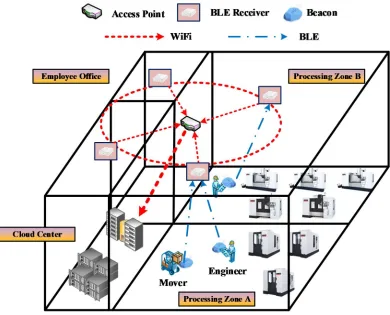
96
characteristics of relatively low power consumption, active push-play, high-throughput, and can be
97
traditional Bluetooth features, BLE which is also called "Bluetooth Smart" can be deployed in harsh
99
environment and is divided into single and dual transmission mode. The operation mechanism of
100
BLE is shown in Figure 1.
101
Figure 1. Client and Server Concept in BLE [6].
102
BLE server (Server) is generally a plug-in small Bluetooth signal transmission module, called
103
Beacon. The main features of Beacon are the power saving, low price and flexible application. Beacon
104
components that have their own unique identification code. The basic structure of unique
105
identification code are three parts, UUID, Major value, Minor value. The UUID is a global
106
independent identifier used to distinguish which App system or company the Beacon belongs to. The
107
UUID contains 32 16-bit codes and is divided into five blocks. The Major value and Minor values are
108
each a group of numbers from 1 to 65535 assigned to a Beacon for more precise identification of the
109
Beacon's role and its use. The Major value is an identifier under the UUID and is usually used to
110
identify a group of Beacon in the same geographical area. Minor number is more detailed
111
identification code, usually used to identify individual Beacon.
112
Nowadays, the application of low-power Bluetooth positioning technology mainly uses "Mobile
113
tracking" to track and implement indoor positioning. As shown in Figure 2, a smart phone with
114
Bluetooth 4.0 technology is used as a data receiving client to scan nearby Beacon signals. After
115
scanning the Beacon node, we can analyze the relative position of each Beacon and the mobile phone,
116
and then learns the location of the current mobile phone body, that is, the position of the mobile
117
phone holder.
118
Therefore, based on the above-mentioned form, the mobile phone begins to collect the Beacon
119
signals nearby. Although Beacon itself is a proactive signal transmission, Beacon is actually a passive
120
terminal in this architecture, and the smart phone is an active terminal that makes a real request. This
121
format in shopping mall applications is indeed well-suited to push advertising or guide customer
122
routes, which is quite reasonable and efficient. However, introducing it into the factory area is
123
inadequate. The fundamental reason is that the functional requirements have different
124
characteristics.
125
Utilizing "Mobile tracking" as the positioning mechanism in factory area will lead to poor energy
126
efficiency. To keep the response time of positioning in bound, mobile phones need to open the
127
functions of Wi-Fi and Bluetooth to transmit data to the database at any time. It can be learned that
128
the mobile phone will consume a lot of power by turning on the Wi-Fi and the Bluetooth at the same
129
time. How to charge the battery to keep the whole position system running is a more difficult
130
Figure 2. Mobile Tracking of BLE.
132
3. Design of Positioning Mechanism based on Bluetooth Low Energy
133
3.1. BLE-Based Location Positioning Mechanism
134
In this research, we propose a BLE-based location positioning mechanism named " Tag tracking".
135
The functionality of mechanism is demonstrated in Figure 3. The concept of "Tag tracking" is as
136
follow:
137
1. Deploying sensor nodes (called BLE receiver in this research) which can actively detect the BLE
138
signal to build a sensing environment.
139
2. Under this environment, we will use beacon as a location detection object by collect BLE signals
140
broadcasted by beacon.
141
3. After collecting these BLE signals, BLE receiver forward them to the cloud computing system.
142
4. The system will compare the position of the BLE receiver to derive the beacon location.
143
Using this format, system can capture information about the location of beacon-equipped
144
personnel. As Beacon lives for up to one year, BLE Receiver will be deployed at a fixed point on the
145
Figure 3. Tag Tracking of BLE.
147
3.2. Regional Label Positioning
148
Despite "Micro-positioning" has higher accuracy and lots of applications, which relatively has
149
larger requirements of digital resources, such as computing efficiency, storage resources and network
150
resources, and expensive costs of deployment and maintenance. In order to import positioning
151
technology into manufacturing process effectively, the "Regional label positioning technology" is
152
proposed to get the location information of target in manufacturing plant that partitions the location
153
of target by section.
154
The scenario will assume that the plant is divided into nine sections, and each block will be
155
installed a node which called BLE Receiver on the ceiling, and every staff will be equipped with a
156
Beacon as BLE signal source. The BLE Receiver captures signal from Beacon to confirm the section
157
that the staff is in. Therefore, the location information of staff can be known indirectly. The illustration
158
3.3. Indoor Positioning Framework based on BLE
161
In this section, we described the fundamental architecture of indoor positioning framework. It
162
is the basic concept for enterprises to run the positioning system. Enterprises can implement it
163
depending on the different situation. The fundamental architecture is shown in Figure 5. It is divided
164
into three parts and is illustrated as below:
165
1. IoT based on BLE: Deploying the BLE IoT is the first step. The enterprise have to install the
166
beacon sensors on each area in the factory. The main purpose is to provide an environment for
167
indoor positioning. As long as we know which area that employees are located in the factory,
168
we can efficiently run various management command by the employee distribution. In the
169
proposed framework, we only need the area that employee located not the exact position.
170
Therefore, the location with high precision is better but not necessary. The stability and reliability
171
of the entire system is the more important. Without high precision, the system can be running
172
smoothly. In this research, we propose a wireless sensor network to construct the environment
173
for IoT based on BLE.
174
2. Mobile application: One significant attribute of BLE is fully compatible with classic Bluetooth.
175
Nowadays, almost all the mobile phones have deployed classic Bluetooth. Inevitably, a proper
176
mobile application is necessary to support the BLE. Google's Android and Apple's iOS are
177
operating systems used primarily in mobile technology. Comparing with iOS, android is easier
178
to design the application program. The hardware cost is relatively lower too. For most of
179
enterprises, the android-based mobile application is recommended. According to above,
180
android-based mobile application is considered an important part in the architecture. The basic
181
purpose of android-based mobile application is to make the communication of beacons and
182
mobile phones. Receiving the UUID of beacon and send the data to the cloud computing system
183
by Wi-Fi or 3G. Then the system will search the beacon information by the UUID and update
184
employee’s location according to the information. Moreover, enterprise can customize the
185
function of the mobile application such as broadcast, map of the factory, punch in, etc… It’s a
186
wide range of uses. In this research, we utilize website with RWD instead of App as user
187
interface to reduce the research cost.
188
3. Cloud Computing System: The third part of the architecture is cloud computing system. With
189
the IT system, employee management will gain a lot of advantages. It reduces the paper work
190
and make the management performance better. Another advantage is to make up the
191
inadequacies of mobile application, the second part in the architecture. Thus, we consider that
192
cloud computing system is a best solution. It offer the high ability of computing and data storing
193
for the entire frame work. All related data (such as Beacon data, employee information, factory
194
information, etc…) can store in the cloud data server. Moreover, utilizing cloud computing
195
system to perform the complex operation instead of doing that by mobile device can reduce the
196
load of mobile device. In ideal situation, we don’t expect that mobile device consume too much
197
energy. We considered the mobile device is only a middle tool to transmit the data and user
198
command then display the result from the cloud computing system. Another reason of using
199
cloud computing system is that it offers the enterprises much space to design the function of
200
entire system. The Enterprises can extend the extra feature like monthly employee performance
201
analysis. Besides, the concept of utilizing cloud computing system is combining the IT system
202
into the proposed framework as the supplement. Therefore the proposed framework is
203
compatible with ERP system. Enterprises can adopt ERP system into the fundamental
204
Figure 5. Indoor Positioning Framework based on BLE.
206
4. Implementation of Positioning System Based on Bluetooth Low Energy
207
4.1. Deployment of BLE-Based Wireless Sensor Network
208
The main purpose is to construct the wireless environment to transmit the data of element’s
209
location information. There are three kinds of nodes in this wireless sensor network.
210
1. Beacon: Deployed on a specific object, which is usually the object that needs to retrieve location
211
information. This research is mainly conducted by field staff.
212
2. BLE receiver: Configured in a specific area for receiving signals from all location information
213
broadcast points in the area and forwarded to the data access point.
214
3. Access point: Receive the data forwarded from the location information collection point, and
215
send it to the data storage center.
216
In this study, a large number of Beacon, BLE receiver and access point are deployed in the factory
217
to make the intranet architecture. The deployment diagram is shown in Figure 6. In order to distribute
218
the signal of network evenly in the plant area, access point and BLE Receiver will be placed on the
219
ceiling of the plant to prevent the interference of the machine or personnel, which will lead to the
220
omission of signal reception.
221
BLE IoT
Beacon 1 Beacon 2
Moblie application Cloud computing system
Tablet
Moblie phone laptop Device Area 1
BLE
User
Director
Operator Employee
Location display
Employee Info display Dispatch App function
Operate
Management System
Other System Position
System Cloud Server
Staff Data
others Beacon Data
Data Server Request Respond
Data
Other function Beacon n
Beacon 1 Beacon 2 Area n
UUID Major value
Minor value
TX Power
3G or WiFi
UUID
Command
3G or WiFi
Data
Figure 6. Illustration for Deployment of BLE-based Wireless Sensor Network.
222
4.2. BLE Signal Acquisition Mechanism
223
In this study, the part of BLE positioning information acquisition is divided into BLE signal
224
reception and data sending back to cloud database. First step is initialization, when BLE Receiver is
225
started, it will automatically connect to Wi-Fi on the factory and load the script to scan the
226
surrounding Signal from Beacon. After scanning completed, BLE Receiver detect the Beacon ID and
227
adopt signal acquisition algorithm to define the number of simultaneous connections, polling
228
interval, data sizes and error feedback. BLE Receiver filters the noise to improve the signal accuracy
229
and achieves high-performance in speed of data acquisition and reliability of connection, and then
230
send the signal from all of surrounding Beacon node back to the data center. The flow chart is
231
Initial Database parameter
Bluetooth is ON
Set BLE Scan parameter
Start Scanner
Choose Scanning Method
Get UUIDList from Database
UUID of beacon is in UUIDList BeaconList is
EOF
Push Beacon from BeaconList Set beacon to
cur_beacon Add cur_beacon
to beaconList If cur_beacon is in
pre_beaconList
Get pre_beacon with the same
UUID
Add cur_rssi to rssiList of pre_beacon
pre_beaconList is EOF
Send message in to database Push beacon from
pre_beaconList
Choose MaxRssi of beacon and make beacon data
message Add cur_beacon
to pre_beaconList
End Yes
No
Yes No
Yes No
No
Yes Yes
No
Figure 7. Flow Chart of Signal Acquisition Mechanism based on BLE.
233
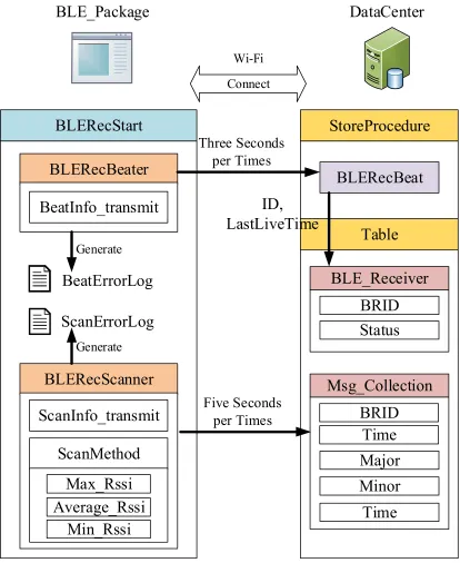
4.3. Implementation of Program --- BLE Package
234
To implement signal acquisition mechanism based on BLE, we design a program, named BLE
235
Package, which has two modules, BLERecBeater and BLERecScanner, to collection the Low-power
236
Bluetooth signal data. BLE Package would keep running on Bluetooth receiver. It’s coding by Python
237
language which has high compatibility with raspberry pie zero, the Bluetooth receiver. Since the
238
Bluetooth receiver will be deployed in a large number of factory environment, how to collection
239
signal data efficiently and flexibly is key point. Therefore, BLE Package provides three signal
240
acquisition methods depended on RSSI value of the collected Bluetooth signals in the period of data
241
pre-processing. The three method would respectively choose the maximum RSSI value, the average
242
RSSI value and the minimum RSSI value as the capture signal of the return information. Because BLE
243
Package is written in kit style, users can directly run it by simply calling the BLERecStart function.
244
The data flow architecture of BLE package is shown in Figure 8. The main function, named
245
“BLERecStart”, will driver two modules, “BLERecBeater” and “BLERecScanner”. The process of two
246
1. BLERecBeater: To ensure BLE Package is in normal operation, BLERecBeater would periodically
248
transmission data to update the operation status of BLE Receiver in datacenter. When the signal
249
from BLERecBeater is interrupted, it can be determined that the BLE receiver is faulty. Moreover,
250
a log file of this program will be constantly updated and record every steps when the heartbeat
251
signal is sent to help engineers fix the program error.
252
2. BLERecScanner: This module dominates the scanning and preliminary data processing of the
253
BLE signals around the area. It also generates a log file to help engineers tracking the related
254
errors. The default signal acquisition method use maximum RSSI value as the primary returned
255
value for datacenter.
256
Figure 8. BLE Package Operation Diagram.
257
5. Discussion
258
BLE_Package
DataCenter
BLERecStart
BLERecScanner
BLERecBeater
Table
BLE_Receiver
BRID
Status
ScanErrorLog
BeatErrorLog
Connect
Wi-Fi
Msg_Collection
BRID
Time
Major
Minor
Time
Three Seconds
per Times
Five Seconds
per Times
Generate
Generate
BeatInfo_transmit
ScanInfo_transmit
ScanMethod
Max_Rssi
Average_Rssi
Min_Rssi
StoreProcedure
BLERecBeat
In this research, Bluetooth Low Energy (BLE) and Wi-Fi are used as the wireless communication
259
protocol in the network. The WSN (Wireless Sensor Network) is deployed as the environment of IoT
260
to integrate the cloud services The contributions of this research are as follows:
261
1. Providing a method to establish the WSN based on BLE in the factory. The location of employee,
262
machine and product in the factory or in the manufacturing process can be collected effectively.
263
This is the basis for developing the location-related application of manufacturing industry.
264
2. Develop a deployment strategy to achieve BLE signal collection in a factory environment so that
265
enterprises can import IoT environments at low cost into the factory. A network management
266
system which reduce the integration threshold and improve the flexibility of deployment and
267
maintenance is also implemented to enhance the willingness of enterprises to deploy.
268
3. We purposed a novel framework for positioning based on BLE. Taking the advantage of BLE,
269
manufacture enterprises can adopt the framework without spending high cost. The novel
270
framework consists of IoT, Cloud Computing System and mobile application. It allows
271
enterprises design customized function in CCS or in mobile application for the purpose.
272
Based on the indoor positioning technique, we also give the three basic instance to describe how the
273
framework working. Although the framework has such many benefits, it has some problems to be
274
solved. The biggest one is the signal propagation. In the factory, there are many factors will cause
275
signal attenuation, such as temperature, transmission and reflection properties of building materials
276
and machine, and interference from other devices [4].
277
Acknowledgments: We are grateful to Ministry of Science and Technology for providing funding and technical
278
support for this study, serial No. 105-2221-E-006-093-MY2. Because of the support of MOST, this study could be
279
conducted smoothly.
280
Author Contributions: Conceptualization, Shang-Liang Chen; Data curation, Cheng-Chia Hsu; Funding
281
acquisition, Shang-Liang Chen; Investigation, Cheng-Chia Hsu; Methodology, Shang-Liang Chen; Project
282
administration, Shang-Liang Chen; Software, Cheng-Chia Hsu and I-Ching Li; Supervision, Shang-Liang Chen;
283
Validation, Cheng-Chia Hsu and I-Ching Li; Visualization, Cheng-Chia Hsu and I-Ching Li; Writing – original
284
draft, Cheng-Chia Hsu; Writing – review & editing, Shang-Liang Chen and I-Ching Li.
285
Conflicts of Interest: The authors declare no conflict of interest.
286
References
287
1. S. Wang, et al, “Towards smart factory for industry 4.0: a self-organized multi-agent system with big data
288
based feedback and coordination,” Computer Networks, Vol. 101, pp. 158-168, 2016.
289
2. D. Gorecky, et al, “Human-machine-interaction in the industry 4.0 era,” Industrial Informatics (INDIN),
290
2014 12th IEEE International Conference on. IEEE, 2014.
291
3. M. Brettel, et al, “How virtualization, decentralization and network building change the manufacturing
292
landscape: An industry 4.0 perspective,” International Journal of Mechanical, Industrial Science and
293
Engineering, Vol. 8.1, pp. 37-44, 2014.
294
4. T. Stock, G. Seliger, “Opportunities of sustainable manufacturing in industry 4.0,” Procedia Cirp Vol. 40,
295
pp. 36-541, 2016.
296
5. J. Koch, et al, “Indoor localisation of humans, objects, and mobile robots with RFID infrastructure,” Hybrid
297
Intelligent Systems, 2007. HIS 2007. 7th International Conference on. IEEE, 2007.
298
6. N. Li, et al, “Performance-based evaluation of RFID-based indoor location sensing solutions for the built
299
environment,” Advanced Engineering Informatics, Vol. 25.3, pp. 535-546, 2011.
300
7. T. Teixeira, et al, “A survey of human-sensing: Methods for detecting presence, count, location, track, and
301
identity,” ACM Computing Surveys, Vol. 5.1, pp. 59-69, 2010.
302
8. R. Tesoriero, et al, “Improving location awareness in indoor spaces using RFID technology,” Expert
303
Systems with Applications, Vol. 37.1, pp. 894-898, 2010.
304
9. R. Tesoriero, et al, “Using active and passive RFID technology to support indoor location-aware systems,”
305
IEEE Transactions on Consumer Electronics, Vol. 54.2, 2008.
306
10. M. Andersson, “Use case possibilities with Bluetooth low energy in IoT applications,” White Paper, 2014.
307
11. W. Roy, et al, “Bluetooth LE Finds Its Niche,” IEEE Pervasive Computing, Vol No. 12, Issue No. 4, pp.12 –
![Table 1. Different Methods for the Perception of Human proposed by Teixeira et al. [7]](https://thumb-us.123doks.com/thumbv2/123dok_us/8080091.1348189/3.595.33.573.419.540/table-different-methods-perception-human-proposed-teixeira-et.webp)
![Figure 1. Client and Server Concept in BLE [6].](https://thumb-us.123doks.com/thumbv2/123dok_us/8080091.1348189/4.595.211.383.128.298/figure-client-and-server-concept-ble.webp)