AN EXPERIMENTAL SETUP FOR THE STUDY OF THE STEADY AIR
FLOW IN A DIESEL ENGINE CHAMBER
Joaquín FERNÁNDEZ(1), Emilio José VEGA(1), Alejandro CASTILLA(2), Alberto MARCOS(1), José María MONTANERO(1)and Raúl BARRIO(3)x
1. I
NTRODUCTIONAbstract:We present an experimental setup for studying the steady air flow in a diesel engine chamber. An engine block containing the inlet manifold was placed on a test bench. A steady air stream crossed the inlet manifold and entered a glass chamber driven by a fan. A PIV system was set up around the bench to measure the in-chamber flow. An air spray gun was used as seed generator to producing sub-millimeter droplets, easily dragged by the air stream. Images of the in-flow chamber were acquired in the course of the experiments, and processed to measure the velocity field. The pressure drop driven the air current and the mass flow rate were also measured.
The flow through the inlet manifold has a considerable influence on both the engine's efficiency and pollutant emissions. In particular, the engine's power is approximately proportional to the mass flow rate crossing the engine chamber [1, 2]. The structure of the flow plays an important role, because the flow direction and magnitude are the dominant factors in the combustion chamber. In particular, the flow pattern inside the chamber greatly affects both the fuel and oxidant distributions, and thus the combustion process.
Normally, a series of experimental measurements are used to estimate certain coefficients that characterize globally the flow into the engine, such as the discharge coefficient, swirl, and tumble numbers [3]. Although there are previous experimental investigations by different techniques in diesel engines, still there is a good scope to study these flows under different conditions. The development of experimental techniques to precisely measure the velocity field inside the chamber constitutes a fundamental step in the design of more efficient engines.
x (1)
Departamento de IMEM, Universidad de Extremadura. Avda. de Elvas s/n, 06006 Badajoz (Extremadura), Spain. E-mail: [email protected]
(2)
Deutz Diter S.A. Ctra. Badajoz-Granada, km 74,6. 06300 Zafra (Extremadura), Spain (3)
Departamento de Energía, Universidad de Oviedo. Campus de Viesques s/n, 33203 Gijón (Asturias), Spain
In order to simplify the analysis, a steady air flow is established in the engine [4] by replacing the piston closing the cylinder with a fan. The fan generates a pressure difference between the entrance of the inlet manifold and the bottom of the cylinder. The air flows through the system for a fixed valve aperture driven by the constant pressure drop. In this way, one straightforwardly obtains the dependence of the air mass flow on the valve aperture for a fixed pressure difference. The velocity field in the chamber can be reconstructed by acquiring PIV images of the several regions of the chamber. This procedure allows one to gain certain insight into the dependence of the in-chamber flow with respect to the inlet manifold geometry. This steady approximation neglects, however, both the dynamic effects and the influence of combustion.
The main purpose of this work is to design and adjust an experimental setup based on the Particle Image Velocimetry (PIV) technique to capture the flow distribution inside an engine chamber.
2. T
ESTF
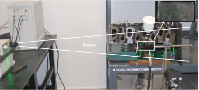
ACILITYThe experiment was performed on a test bench (figure 1) [5], which is an industry standard for these types of measurements. The engine block containing the inlet manifold was placed on the bench. In order to avoid both laser beam reflections and optical distortion, the cylindrical chamber was replaced by the corresponding circumscribed parallelepiped, which was made of perspex. A stagnation tank was placed between the fan and the chamber to ensure steady flow in the chamber. A pressure drop was established between the inlet manifold and the bottom of the chamber by means of a variable speed fan. The pressures at the mouth of the inlet manifold tube (atmospheric pressure) and at the bottom of the chamber were determined using static pressure meters. The mass flow rate was measured using a calibrated nozzle equipped with differential pressure meters. The valve lift was determined with a micrometer.
A PIV system was set up around the bench to measure the in-chamber flow velocities. This PIV system (figures 1 and 2) consists of a TSI Nd:Yag Nano S 65-15 double pulsed laser producing co-linear beams at 532 nm wavelength and approximately 65 mJ per pulse, with the time between pulses set to 10 beams are expanded by a cylindrical lens, -15 mm fl, and directed into a full length glass liner. Images of 1600 by 1200 pixels were acquired in the course of the experiments by using a PowerView Plus 2MP PIV Camera CCD sensor with a Nikon F-mount 50mm lens. The camera and laser system is controlled through INSIGHT 3G software. Image acquisition is followed by a processing application.
Figure 1:Test bench and PIV system
3. M
ETHODOLOGYThe way of operating the test facility is to set first an inlet valve lift, and then to apply a pressure drop across the valve gap by selecting the fan speed. The steady flow was measured for a valve lift of 7 mm, while the applied pressure drop was 20 mbar (the atmospheric pressure was 994 mbar while the pressure inside the chamber was 974 mbar). The calibration target was attached on a rectangle of the same dimensions as those of the chamber, and placed behind the chamber. The camera was focused on the chamber axial midplane, avoiding measurements close to the walls where optical distortion may affect the results.
For a uniform and adequate seeding, the particles should mix properly with the incoming air entering the inlet section. For this purpose, an air spray gun was mounted in front of the inlet section (figure 1). This seed generator produced sub-millimeter droplets, which were easily dragged by the air stream.
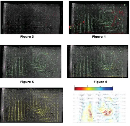
The images acquired in the course of the experiments were processed following several steps. The velocity vectors were calculated through INSIGHT 3G software (figures 3 and 4). About 10% of the vectors obtained were not physically meaningful. In order to eliminate those spurious velocities, each vector was compared with a reference value, calculated as the average over the vicinity of that vector. If the difference exceeded a certain threshold, that velocity vector was rejected. Figure 5 shows the results obtained after applying this procedure to figure 4. Finally, the set of velocity vectors was completed (figure 6), and the results were smoothed (figures 7 and 8) following standard methods.
To summarize, an experimental setup was designed and adjusted to measure the velocity field inside the chamber of a combustion engine. Preliminary results show that the procedure provides reliable values for the velocity field which can be compared with theoretical predictions from numerical simulations.
Figure 3 Figure 4
Figure 5 Figure 6
Figure 7 Figure 8
4. R
EFERENCES[1] Renato Della Volpe: Impianti Motori per la Propulsione Navale, Liguori Editori, Italy, 2001.
[2] Garro A.: Progettazione Strutturale del Motore, Levrotto&Bella, Italy, 1992.
[3] Heywood J. B.: Internal combustion engine fundamentals, Mc-Graw Hill, New York, 1988.
[4] Genta G.: Meccanica dell’Autoveicolo, Levrotto&Bella, Italy, 2000.